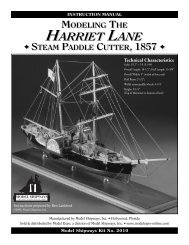
download benjamin latham instruction manual
download benjamin latham instruction manual
download benjamin latham instruction manual

Create successful ePaper yourself
Turn your PDF publications into a flip-book with our unique Google optimized e-Paper software.
If done properly, the chainplates should be recessed into the<br />
hull so they are flush with the hull planking. Their heads<br />
should poke up through the rails (see figure 69). This will entail<br />
some fancy drilling and cutting, not to mention giving your<br />
layout work very careful attention. Nails for fastening the<br />
plates in true-scale fashion are no longer available. So, using a<br />
No. 75 bit, drill the chainplates to accept lill pins. Hold the pins<br />
in place on the hull and drive them in with a driver tool. If you<br />
prefer smaller heads on the pins, they may be filed smaller and<br />
flatter, using a pin vise to hold them during the process.<br />
2. Rigging the Bowsprit<br />
Inner & Outer Bobstays: Make and set up the inner and outer<br />
bobstays (see plan sheets 2 & 4). These should be served over<br />
their whole length. The lower ends should be eyespliced and<br />
shackled into the bobstay irons. The upper ends should be eyespliced,<br />
shackled to turnbuckles and set up taut. The lower<br />
ends of the bobstays on the lifesize vessel were often given an<br />
extra heavy serving. In addition, the outer received a covering<br />
of rawhide or heavy leather called a stradden, which was laced<br />
on the topside of the stay. This was done to prevent chafing<br />
from the ground tackle while lying at anchor. Many operators<br />
of mackerel schooners engaged in summer work dispensed<br />
with the heavy bobstay coverings.<br />
Bowsprit Guys: Next to be fitted are the bowsprit guys. They<br />
should be spliced and served in similar fashion to the bobstays,<br />
minus the stradden. Instead, give them an extra heavy service,<br />
from their inboard ends out to a point abreast of the gammoning.<br />
3. Turnbuckles<br />
If the modelmaker wants to adjust the forward stay rigging, he<br />
can purchase four #700 working turnbuckles which will do the<br />
job well, at slight sacrifice in scale appearance. Otherwise,<br />
dummy turnbuckles can be fabricated with wire and solder<br />
(see figure 70).<br />
4. Footropes & Manropes<br />
These are finer secondary elements of the bowsprit rigging.<br />
They also should be served overall, but rigged very slack as<br />
shown on the rigging plan. The bowsprit guys and footropes<br />
should be linked together by tarred manila “stirrups” which<br />
should be done similar to ratlines (see figure 71).<br />
5. Fore & Main Shrouds<br />
Pairing & Seating of Shroud Lines: Shroud lines must be put<br />
on before the stays and before the topmasts can be fitted. Each<br />
mast will have a 3-line shroud unit on both its sides, port and<br />
starboard. Each of the lines will extend from the mast heads to<br />
the chainplates (see plans). You may work on one or both masts<br />
at the same time. Begin with the first pair of shroud lines at starboard<br />
and then the second pair at port (see figures 72a). Each<br />
pair is comprised of a single length of cordage that should be<br />
doubled over and seized together to form a loop that will fit<br />
loosely around each mast head (see figure 72b). When you have<br />
finished these four pairs, they must be served. Follow the serving<br />
procedure for the shroud “pairs” in the discussion on serving<br />
that follows before going on the the last of the shroud lines.<br />
After serving the shroud pairs, you may begin the “single”<br />
shroud line that should be positioned in between the lines of<br />
each finished pair. To create this “single” center shroud line<br />
you will need two lengths of cordage for joining at each mast<br />
head. One end of each of these two lengths should be wrapped<br />
around the mast head to meet the other. Draw just enough excess<br />
length, so that you can cut-splice them together (see also<br />
figure 72a). This joining will form a single continuous line that<br />
you can extend downward at both port and starboard in between<br />
each of the two pairs of both masts. Follow the serving<br />
procedure in the next paragraph.<br />
Serving the Shroud Lines: The shroud “pairs” should be<br />
served over their entire lengths. They require additional heavy<br />
servings around the eyes at the chainplates, which on the lifesize<br />
vessel were covered with canvas and well tarred. The extra<br />
serving will look well on the model, but canvas is tricky to simulate<br />
and is probably best omitted.<br />
Follow the same serving practice on the shroud “singles” as<br />
described in the previous paragraph, but in this case, the heavy<br />
service extends below the levels of the gaff jaws if the fore and<br />
main sails are to be set. The extra service was done on the lifesize<br />
vessel to prevent the gaffs from chafing the shrouds.<br />
Shroud Line Deadeyes: The lower ends of the shroud lines<br />
were, in actual practice, spliced around the deadeyes. Each<br />
shroud end should be first served where the deadeye should<br />
be fitted. An eyesplice then should be made and covered with<br />
serving in the same fashion as was done on the main lengths of<br />
the shroud lines. The deadeye splice may be substituted with a<br />
very neat job of seizing and tapering of the shroud end along<br />
its doubling, followed by serving (see figure 73).<br />
FIG. 73 – Shroud Deadeyes<br />
Wire shroud is shown;<br />
cordage can be substituted<br />
on model<br />
1 2<br />
Shroud served in<br />
way of deadeye<br />
Shroud end<br />
tapered by cutting<br />
out strands<br />
Shroud spliced<br />
ACTUAL PRACTICE<br />
1 2<br />
3<br />
SIMPLIFIED FOR MODELS<br />
Service<br />
completed<br />
Seizing covers<br />
doubling<br />
37