download benjamin latham instruction manual
download benjamin latham instruction manual
download benjamin latham instruction manual

You also want an ePaper? Increase the reach of your titles
YUMPU automatically turns print PDFs into web optimized ePapers that Google loves.
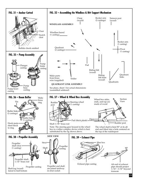
FIG. 31 – Anchor Catted<br />
FIG. 32 – Assembling the Windlass & Bitt Support Mechanism<br />
Clasp<br />
(wood)<br />
Rocker arm<br />
(2 castings)<br />
Samson post<br />
(wood)<br />
WINDLASS ASSEMBLY<br />
Buffalo chock omitted<br />
FIG. 35 – Pump Assembly<br />
Cleat<br />
Snatch<br />
cleat<br />
Windlass barrel<br />
(1 casting)<br />
Quadrant<br />
(2 castings)<br />
Rocker arm<br />
(1 casting)<br />
Pivot<br />
(1 casting)<br />
Pump bowl<br />
casting<br />
Plunger<br />
casting<br />
Pump<br />
base<br />
casting<br />
Pump<br />
brake<br />
casting<br />
Make parts<br />
from brass<br />
wire (supplied)<br />
Solder<br />
QUADRANT LINK ASSEMBLY<br />
See plans, sheet 1 for actual dimensions<br />
(assembled soldered)<br />
Pad<br />
Riding bitt<br />
(wood)<br />
Riding<br />
bitt knee<br />
(wood)<br />
Quadrants<br />
Quadrant<br />
links<br />
FIG. 36 – Boom Buffer<br />
Pin<br />
Make<br />
brass<br />
ring<br />
FIG. 37 – Wheel & Wheel Box Assembly<br />
Rudder<br />
post<br />
Steering wheel<br />
(1 casting)<br />
Wheel box sides,<br />
ends, and top are<br />
made of wood<br />
Section<br />
View<br />
Buffer links<br />
(2 castings)<br />
Hook main<br />
sheet block<br />
to ring<br />
Buffer link<br />
(1 casting)<br />
Shaft 1/16” brass rod<br />
Pad (thick plank)<br />
Note: The steering gear housed in the wheel<br />
box is a rather complex device which is best<br />
substituted by the rig shown above.<br />
Open<br />
Open<br />
Rudder post<br />
The wheel shaft is bent 90° at its aft<br />
end and fitted into a hole centered on<br />
the top of the rudderpost<br />
FIG. 38 – Propeller Assembly<br />
SIDE VIEW<br />
FIG. 39 – Exhaust Pipe<br />
Propeller<br />
shaft strut<br />
(1 casting)<br />
Strut<br />
Shaft<br />
Propeller<br />
casting<br />
Jiber box<br />
Propeller shaft-<br />
1/16” brass rod<br />
Propeller casting<br />
Shaft log (wood)<br />
faired to hull bottom<br />
Propeller and shaft<br />
are joined midway<br />
in strut socket<br />
Exhaust pipe casting<br />
Aft end of exhaust<br />
pipe should project<br />
1/16”- 3/32” beyond<br />
transom<br />
23