SIOV Metal Oxide Varistors - DEMAR
SIOV Metal Oxide Varistors - DEMAR
SIOV Metal Oxide Varistors - DEMAR

You also want an ePaper? Increase the reach of your titles
YUMPU automatically turns print PDFs into web optimized ePapers that Google loves.
Selection Procedure<br />
2.4 Series and parallel connection<br />
2.4.1 Series connection<br />
<strong>SIOV</strong> varistors can be connected in series for more precise matching to uncommon voltage ratings<br />
or for voltage ratings higher than those available. For this purpose the types selected should be of<br />
the same series (i. e. same diameter). The maximum permissible operating voltage in series configuration<br />
is produced by adding the maximum DC or AC voltages of the varistors.<br />
2.4.2 Parallel connection<br />
<strong>Metal</strong> oxide varistors can be connected in parallel in order to achieve higher current load capabilities<br />
or higher energy absorption than can be obtained with single components. To this end, the intended<br />
operating point in the surge current region (see section 1.5) must be taken into account.<br />
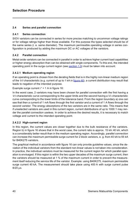
2.4.2.1 Medium operating region<br />
If an operating point is chosen from the derating fields that is in the highly non-linear medium region<br />
of the V/I characteristic (e.g. current of up to 1 kA in figure 46), a current distribution may result that<br />
leads to negation of the intended purpose.<br />
Example surge current i* = 1 A in figure 16:<br />
In the worst case, 2 varistors may have been chosen for parallel connection with the first having a<br />
V/I characteristic curve corresponding to the upper limits and the second having a V/I characteristic<br />
curve corresponding to the lower limits of the tolerance band. From the region boundary a) one can<br />
see that then a current of 1 mA flows through the first varistor and a current of 1 A flows through the<br />
second varistor. The energy absorptions of the two varistors are in the same ratio. This means that<br />
if unselected varistors are used in this current region, current distributions of up to 1000:1 may render<br />
the parallel connection useless. In order to achieve the desired results, it is necessary to match<br />
voltage and current to the intended operating point.<br />
2.4.2.2 High-current region<br />
In this region, the current values are closer together due to the bulk resistance of the varistors.<br />
Region b) in figure 16 shows that in the worst case, the current ratio is approx. 15 kA:40 kA, which<br />
is a considerably better result than in the medium operating region. Accordingly, parallel connection<br />
can increase the maximum permissible surge current for 2 block varistors, e. g. from 40 kA to 55 kA<br />
for B40K275 varistors.<br />
The graphical method in accordance with figure 16 can only provide guideline values, since the deviation<br />
of the individual varistors from the standard non-linear values is not taken into consideration.<br />
In practice, the individual varistors must be measured for the current region for which parallel operation<br />
is envisaged. If this region is within the two upper decades of the maximum surge current, then<br />
the varistors should be measured at 1 % of the maximum current in order to prevent the measurement<br />
itself reducing the service life of the varistor. Example: using B40K275, maximum permissible<br />
surge current 40 kA. The measurement should take place using 400 A with surge current pulse<br />
8/20 µs.<br />
40 Siemens Matsushita Components
![Equações Diferenciais Ordinárias Lineares de 2ª Ordem [ ] [ ] - DEMAR](https://img.yumpu.com/43234810/1/184x260/equaaaues-diferenciais-ordinarias-lineares-de-2a-ordem-demar.jpg?quality=85)