SIOV Metal Oxide Varistors - DEMAR
SIOV Metal Oxide Varistors - DEMAR
SIOV Metal Oxide Varistors - DEMAR

You also want an ePaper? Increase the reach of your titles
YUMPU automatically turns print PDFs into web optimized ePapers that Google loves.
Application and Design Examples<br />
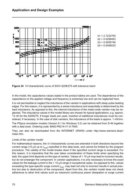
b1 = 2.7233755<br />
b2 = 0.0258453<br />
b3 = 0.0005746<br />
b4 = 0.0046033<br />
Figure 34 V/I characteristic curve of <strong>SIOV</strong>-S20K275 with tolerance band<br />
In the model, the capacitance values stated in the product tables are used. The dependence of the<br />
capacitance on the applied voltage and frequency is extremely low and can be neglected here.<br />
It is not permissible to neglect the inductance of the varistor in applications with steep pulse leading<br />
edges. For this reason, it is represented by a series inductance and essentially is determined by the<br />
lead inductance. As opposed to this, the internal inductance of the metal oxide varistor may be neglected.<br />
The inductance values in the model library are chosen for typical applications, e.g. approx.<br />
13 nH for the S20K275. If longer leads are used, insertion of additional inductances must be considered,<br />
if necessary. In the case of disk varistors, the inductance of the leads is approx. 1 nH/mm.<br />
The PSpice simulation models (Version 6.1 for Windows 3.2) can be obtained from S+M together<br />
with a data book. Ordering code: B462-P6214-V1-X-7600.<br />
They can also be downloaded from the INTERNET (WWW) under http://www.siemens.de/pr/<br />
index.htm.<br />
Limits of the varistor model<br />
For mathematical reasons, the V/I characteristic curves are extended in both directions beyond the<br />
current range (10 µA up to I max ) specified in this data book, and cannot be limited by the program<br />
procedure. The validity of the model breaks down if the specified current range is exceeded. For<br />
this reason, it is imperative that the user takes consideration of these limits when specifying the<br />
task; the upper limit depends on the type of varistor. Values of < 10 µA may lead to incorrect results,<br />
but do not endanger the component. In varistor applications, it is only necessary to know the exact<br />
values for the leakage current in the < 10 µA range in exceptional cases. As opposed to this, values<br />
exceeding the type-specific surge current I max , may lead not only to incorrect results in actual practice<br />
but also to destruction of the component. Apart from this, the varistor model does not check<br />
adherence to other limit values such as maximum continuous power dissipation or surge current<br />
70 Siemens Matsushita Components
![Equações Diferenciais Ordinárias Lineares de 2ª Ordem [ ] [ ] - DEMAR](https://img.yumpu.com/43234810/1/184x260/equaaaues-diferenciais-ordinarias-lineares-de-2a-ordem-demar.jpg?quality=85)