
Create successful ePaper yourself
Turn your PDF publications into a flip-book with our unique Google optimized e-Paper software.
<strong>MIRAGE</strong> Service Manual <strong>Carefree</strong> <strong>of</strong> <strong>Colorado</strong><br />
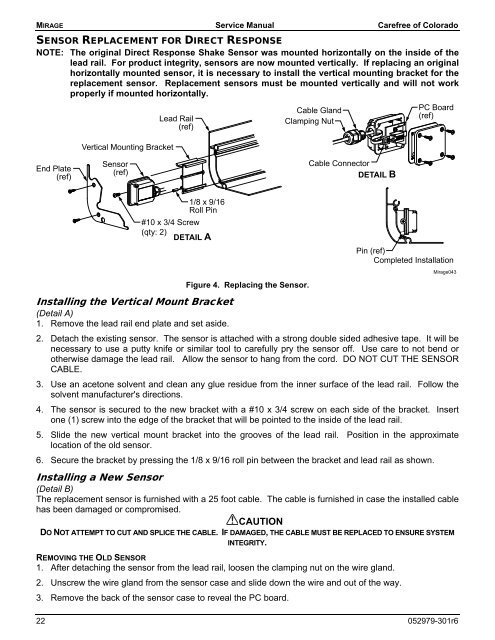
SENSOR REPLACEMENT FOR DIRECT RESPONSE<br />
NOTE: The original Direct Response Shake Sensor was mounted horizontally on the inside <strong>of</strong> the<br />
lead rail. For product integrity, sensors are now mounted vertically. If replacing an original<br />
horizontally mounted sensor, it is necessary to install the vertical mounting bracket for the<br />
replacement sensor. Replacement sensors must be mounted vertically and will not work<br />
properly if mounted horizontally.<br />
Vertical Mounting Bracket<br />
Lead Rail<br />
(ref)<br />
Cable Gland<br />
Clamping Nut<br />
PC Board<br />
(ref)<br />
End Plate<br />
(ref)<br />
Sensor<br />
(ref)<br />
Cable Connector<br />
DETAIL B<br />
1/8 x 9/16<br />
Roll Pin<br />
#10 x 3/4 Screw<br />
(qty: 2)<br />
DETAIL A<br />
Figure 4. Replacing the Sensor.<br />
Pin (ref)<br />
Completed Installation<br />
Mirage043<br />
Installing the Vertical Mount Bracket<br />
(Detail A)<br />
1. Remove the lead rail end plate and set aside.<br />
2. Detach the existing sensor. The sensor is attached with a strong double sided adhesive tape. It will be<br />
necessary to use a putty knife or similar tool to carefully pry the sensor <strong>of</strong>f. Use care to not bend or<br />
otherwise damage the lead rail. Allow the sensor to hang from the cord. DO NOT CUT THE SENSOR<br />
CABLE.<br />
3. Use an acetone solvent and clean any glue residue from the inner surface <strong>of</strong> the lead rail. Follow the<br />
solvent manufacturer's directions.<br />
4. The sensor is secured to the new bracket with a #10 x 3/4 screw on each side <strong>of</strong> the bracket. Insert<br />
one (1) screw into the edge <strong>of</strong> the bracket that will be pointed to the inside <strong>of</strong> the lead rail.<br />
5. Slide the new vertical mount bracket into the grooves <strong>of</strong> the lead rail. Position in the approximate<br />
location <strong>of</strong> the old sensor.<br />
6. Secure the bracket by pressing the 1/8 x 9/16 roll pin between the bracket and lead rail as shown.<br />
Installing a New Sensor<br />
(Detail B)<br />
The replacement sensor is furnished with a 25 foot cable. The cable is furnished in case the installed cable<br />
has been damaged or compromised.<br />
CAUTION<br />
DO NOT ATTEMPT TO CUT AND SPLICE THE CABLE. IF DAMAGED, THE CABLE MUST BE REPLACED TO ENSURE SYSTEM<br />
INTEGRITY.<br />
REMOVING THE OLD SENSOR<br />
1. After detaching the sensor from the lead rail, loosen the clamping nut on the wire gland.<br />
2. Unscrew the wire gland from the sensor case and slide down the wire and out <strong>of</strong> the way.<br />
3. Remove the back <strong>of</strong> the sensor case to reveal the PC board.<br />
22 052979-301r6