

Service Handbook - AO Smith Water Heaters
Service Handbook - AO Smith Water Heaters
Service Handbook - AO Smith Water Heaters

Create successful ePaper yourself
Turn your PDF publications into a flip-book with our unique Google optimized e-Paper software.
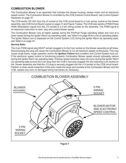
Combustion Blower<br />
The Combustion Blower is an assembly that includes the blower housing, blower motor and an electronic<br />
speed control. The Combustion Blower is controlled by the CCB (Central Control Board), see Control System<br />
Hardware on page 37.<br />
The CCB sends 120 VAC from the J2 socket on the CCB circuit board to a 3 pin wiring socket on the blower<br />
assembly, see CCB Circuit Board Layout on page 41 and Figure 7 below. The CCB also sends a PWM (Pulse<br />
Width Modulation) signal from the J13 socket to a 5 pin wiring socket on the assembly. The PWM signal is<br />
an electronic instruction to start, stop and control blower speed.<br />
The Combustion Blower runs at higher speeds during the Pre/Post Purge operating states and runs at a<br />
lower speed during the Igniter Warm Up operating state, see Table 6 on page 48 for a list of operating states.<br />
The Igniter Status icon is displayed on the Control System LCD during the Igniter Warm Up operating state,<br />
see Table 5 on page 47.<br />
<strong>Service</strong> Note:<br />
The 5 pin PWM signal plug MUST remain plugged in to the 5 pin socket on the blower assembly at all times.<br />
Disconnecting this plug will cause the Combustion Blower to run at maximum speed continuously. This may<br />
cause rough starts, rough operation and/or the Ignition Failure fault condition and Control System lock out.<br />
If the electronic speed control is functioning properly Combustion Blower speed should noticeably reduce<br />
during the Igniter Warm Up operating state. If blower speed reduction does not occur during the Igniter Warm<br />
Up operating state ensure the 5 pin plug from the CCB is securely plugged into the matching 5 pin socket on<br />
the blower assembly and that the J13 plug is securely plugged into the J13 socket on the CCB circuit board.<br />
Perform a close visual inspection of the pins inside the plugs and sockets at the Combustion Blower and the<br />
CCB, replace any worn or damaged wiring harnesses as necessary.<br />
COMBUSTION BLOWER ASSEMBLY<br />
BLOWER<br />
HOUSING<br />
5 PIN<br />
WIRING<br />
SOCKET<br />
BLOWER MOTOR<br />
AND ELECTRONIC<br />
SPEED CONTROL<br />
3 PIN<br />
WIRING<br />
SOCKET<br />
Figure 7<br />
Servicing should only be performed by a Qualified <strong>Service</strong> Agent<br />
11


