

Service Handbook - AO Smith Water Heaters
Service Handbook - AO Smith Water Heaters
Service Handbook - AO Smith Water Heaters

You also want an ePaper? Increase the reach of your titles
YUMPU automatically turns print PDFs into web optimized ePapers that Google loves.
Control System Monitoring<br />
The Control System monitors the “state” of the pressure switch contacts individually through three separate<br />
circuits, see Wiring Diagram on page 44. The state of the switch refers to whether the switch contacts are open<br />
or closed, see Construction & Operation on page 28.<br />
At the beginning of a heating sequence, before the Combustion Blower is energized, the Control System<br />
enters the Input Verification operating state, see Operating States on page 48. During Input Verification the<br />
Control System monitors all three pressure switches to ensure their contacts are in the correct "normal"<br />
state. The Blower Prover switch contacts must be open, the contacts for the Blocked Intake Air and Blocked<br />
Exhaust switches must be closed, see Figure 30 on page 28 and the Sequence Of Operation on page 54.<br />
If any of the pressure switch contacts are not in their correct normal state during Input Verification the Control<br />
System will lock out and display a fault message on the LCD indicating which pressure switch caused the<br />
fault condition, see Figure 31 below. If all system checks pass during the Input Verification operating state the<br />
Control System enters the Pre-Purge operating state and energizes the Combustion Blower.<br />
After the Combustion Blower is energized the Control System must confirm the Blower Prover switch contacts<br />
have closed, see the Sequence Of Operation Flow Chart on page 55. The Blocked Intake Air and Blocked<br />
Exhaust switch contacts must remain closed at all times.<br />
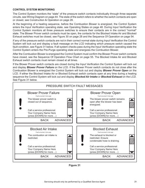
If the Blower Prover switch contacts are closed during the Input Verification the Control System will lock out<br />
and display Blower Prover Failure on the LCD. If the Blower Prover switch contacts do not close after the<br />
Combustion Blower is energized the Control System will lock out and display Blower Prover Open on the<br />
LCD. If either the Blocked Intake Air or Blocked Exhaust switch contacts open at any time during a heating<br />
sequence the Control System will lock out and display Blocked Air Intake or Blocked Exhaust on the LCD.<br />
See Figure 31 below.<br />
PRESSURE SWITCH FAULT MESSAGES<br />
Blower Prover Failure<br />
Fault occurred 2 mins ago<br />
The blower prover switch is<br />
closed out of sequence.<br />
Call a service professional:<br />
Your Company Name Here<br />
(press [DOWN] for more....)<br />
CHANGE BACK ADVANCED<br />
Blower Prover Open<br />
Fault occurred 2 mins ago<br />
The blower prover switch remains<br />
open after the blower has been<br />
energized.<br />
Call a service professional:<br />
Your Company Name Here<br />
(press [DOWN] for more....)<br />
CHANGE BACK ADVANCED<br />
Blocked Air Intake<br />
Fault occurred 2 mins ago<br />
The combustion air intake is<br />
restricted.<br />
Call a service professional:<br />
Your Company Name Here<br />
(press [DOWN] for more....)<br />
CHANGE BACK ADVANCED<br />
Blocked Exhaust<br />
Fault occurred 2 mins ago<br />
The exhaust is blocked or<br />
restricted. Ensure<br />
condensate hose is draining.<br />
Call a service professional:<br />
Your Company Name Here<br />
(press [DOWN] for more....)<br />
CHANGE BACK ADVANCED<br />
Figure 31<br />
Servicing should only be performed by a Qualified <strong>Service</strong> Agent<br />
29


