

Service Handbook - AO Smith Water Heaters
Service Handbook - AO Smith Water Heaters
Service Handbook - AO Smith Water Heaters

You also want an ePaper? Increase the reach of your titles
YUMPU automatically turns print PDFs into web optimized ePapers that Google loves.
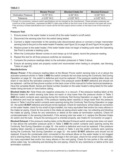
Table 3<br />
Blower Prover Blocked Intake Air Blocked Exhaust<br />
†Activation Pressure +0.75" W.C. -2.00" W.C. +2.00" W.C.<br />
Tolerance ± 0.05" W.C. ± 0.05" W.C. ± 0.05" W.C.<br />
†Though it is uncommon, pressure switch specifications can be changed by the manufacturer. These activation pressures are<br />
current as of the (month/year - expressed as MM/YY) date code printed on the front cover of this manual in the lower left corner.<br />
If the accuracy of these specifications are in doubt call the toll free support phone number on the back cover of this manual to<br />
verify.<br />
Pressure Test:<br />
1. Ensure power to the water heater is turned off at the water heater's on/off switch.<br />
2. Disconnect the sensing tube from the switch being tested.<br />
3. Connect a digital manometer to the sensing tube disconnected above or connect a longer manometer<br />
sensing tube to the port on the water heater if needed, see Figure 32 on page 30 and Figure 34 on page 34.<br />
4. Restore power to the water heater, if the water heater does not begin a heating cycle raise the Operating<br />
Set Point to activate a heating cycle.<br />
5. When the Combustion Blower comes on and ramps up to full speed, record the pressure reading.<br />
6. Repeat this test for all three pressure switches as necessary.<br />
7. Compare the pressure readings taken to the activation pressures in Table 3 above.<br />
8. Ensure all sensing tubes are properly routed and reconnected when testing is complete, see Sensing<br />
Tubes on page 30.<br />
Results/Actions<br />
Blower Prover: If the pressure reading taken at the Blower Prover switch sensing tube is at or above the<br />
activation pressure shown in Table 3 and the switch contacts did not close during the Continuity Test During<br />
Operation on page 32 - the switch is defective and must be replaced. If the pressure reading taken does not<br />
reach or rise above the activation pressure in Table 3 the pressure switch is not defective and should not<br />
be replaced - call the toll free phone number on the back cover of this manual for further technical assistance.<br />
Have the complete Model, Series and Serial number (located on the water heater's rating label) for the water<br />
heater being serviced on hand before calling.<br />
Blocked Intake Air: Note these are negative pressures; in a vacuum. If the pressure reading taken at the<br />
Blocked Intake Air switch sensing tube does not reach or drop lower than the pressure shown in Table 3<br />
and the switch contacts were opening during the Continuity Test During Operation on page 32 - the switch<br />
is defective and must be replaced. If the pressure reading taken reaches or drops lower than the pressure<br />
shown in Table 3 and the switch contacts were opening during the Continuity Test During Operation on page<br />
32 - the switch is not defective and should not be replaced. Check for restrictions at the intake air connection<br />
on the water heater, check for too small of pipe installed, too many equivalent feet and/or too many elbows in<br />
the intake air piping. Check for low points in the intake air piping where water may be collecting and blocking<br />
the intake air piping. Check for any restrictions or debris at the intake air termination outdoors. Check for<br />
condensate/water in the sensing tube/switch, if the sensing tube has water in it, replace the Blocked Intake<br />
Air switch and the tube. Ensure the sensing port is oriented properly, see Intake Air Connection on page 5.<br />
Blocked Exhaust: If the pressure reading taken at the Blocked Exhaust switch sensing tube does not reach<br />
or rise above the activation pressure given in Table 3 and the switch contacts were opening during the<br />
Continuity Test During Operation on page 32 - the switch is defective and must be replaced. If the pressure<br />
reading taken reaches or exceeds the pressure shown in Table 3 and the switch contacts were opening<br />
during the Continuity Test During Operation on page 32 - the switch is not defective and should not be<br />
replaced. Ensure the condensate drain connected to the exhaust elbow on the water heater is not clogged<br />
and is draining freely. Check for restrictions or blockage in the vent pipe, check for too small of pipe installed,<br />
too many equivalent feet and/or too many elbows in the vent piping. Check for low points in the vent pipe<br />
where water may be collecting and blocking the vent piping. Check for any restrictions or debris at the vent<br />
termination outdoors.<br />
Servicing should only be performed by a Qualified <strong>Service</strong> Agent<br />
33


