

Service Handbook - AO Smith Water Heaters
Service Handbook - AO Smith Water Heaters
Service Handbook - AO Smith Water Heaters

Create successful ePaper yourself
Turn your PDF publications into a flip-book with our unique Google optimized e-Paper software.
Flame Sensing Current Test<br />
During the heating cycle the flame sensing current is normally between 8.0 μA and 12.0 μA with a clean<br />
Flame Sensor. Over time the Flame Sensor will accumulate corrosion (rust) and this will reduce flame sensing<br />
current. With heavier use, more heating cycles/greater load, corrosion will occur more quickly.<br />
Measuring flame sensing current requires a test meter with a DC micro amp<br />
function, see Tools Required on page 2. The meter’s selector is set to DC micro<br />
amps. The two test leads from the meter are placed in series with the flame sensing<br />
circuit. This can be done at the spade (male/female) wiring connectors behind the<br />
CCB enclosure or at the J4 spade connection on the CCB circuit board. See Figure<br />
19 below and the CCB Circuit Board Layout on page 41.<br />
To measure flame sensing current turn off power to the water heater and connect<br />
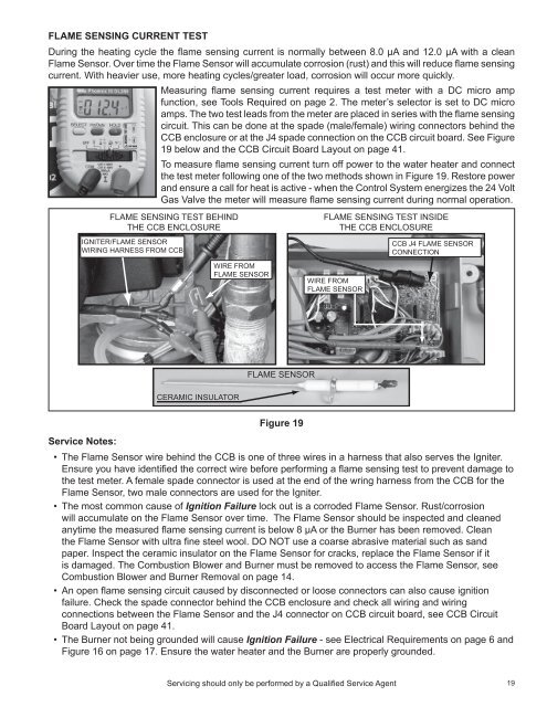
the test meter following one of the two methods shown in Figure 19. Restore power<br />
and ensure a call for heat is active - when the Control System energizes the 24 Volt<br />
Gas Valve the meter will measure flame sensing current during normal operation.<br />
FLAME SENSING TEST BEHIND<br />
THE CCB ENCLOSURE<br />
IGNITER/FLAME SENSOR<br />
WIRING HARNESS FROM CCB<br />
WIRE FROM<br />
FLAME SENSOR<br />
FLAME SENSING TEST INSIDE<br />
THE CCB ENCLOSURE<br />
WIRE FROM<br />
FLAME SENSOR<br />
CCB J4 FLAME SENSOR<br />
CONNECTION<br />
FLAME SENSOR<br />
CERAMIC INSULATOR<br />
Figure 19<br />
<strong>Service</strong> Notes:<br />
• The Flame Sensor wire behind the CCB is one of three wires in a harness that also serves the Igniter.<br />
Ensure you have identified the correct wire before performing a flame sensing test to prevent damage to<br />
the test meter. A female spade connector is used at the end of the wring harness from the CCB for the<br />
Flame Sensor, two male connectors are used for the Igniter.<br />
• The most common cause of Ignition Failure lock out is a corroded Flame Sensor. Rust/corrosion<br />
will accumulate on the Flame Sensor over time. The Flame Sensor should be inspected and cleaned<br />
anytime the measured flame sensing current is below 8 µA or the Burner has been removed. Clean<br />
the Flame Sensor with ultra fine steel wool. DO NOT use a coarse abrasive material such as sand<br />
paper. Inspect the ceramic insulator on the Flame Sensor for cracks, replace the Flame Sensor if it<br />
is damaged. The Combustion Blower and Burner must be removed to access the Flame Sensor, see<br />
Combustion Blower and Burner Removal on page 14.<br />
• An open flame sensing circuit caused by disconnected or loose connectors can also cause ignition<br />
failure. Check the spade connector behind the CCB enclosure and check all wiring and wiring<br />
connections between the Flame Sensor and the J4 connector on CCB circuit board, see CCB Circuit<br />
Board Layout on page 41.<br />
• The Burner not being grounded will cause Ignition Failure - see Electrical Requirements on page 6 and<br />
Figure 16 on page 17. Ensure the water heater and the Burner are properly grounded.<br />
Servicing should only be performed by a Qualified <strong>Service</strong> Agent<br />
19


