

Service Handbook - AO Smith Water Heaters
Service Handbook - AO Smith Water Heaters
Service Handbook - AO Smith Water Heaters

Create successful ePaper yourself
Turn your PDF publications into a flip-book with our unique Google optimized e-Paper software.
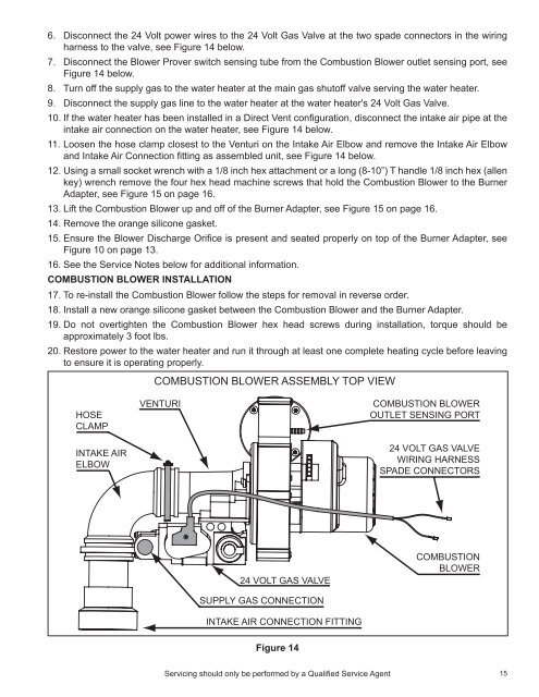
6. Disconnect the 24 Volt power wires to the 24 Volt Gas Valve at the two spade connectors in the wiring<br />
harness to the valve, see Figure 14 below.<br />
7. Disconnect the Blower Prover switch sensing tube from the Combustion Blower outlet sensing port, see<br />
Figure 14 below.<br />
8. Turn off the supply gas to the water heater at the main gas shutoff valve serving the water heater.<br />
9. Disconnect the supply gas line to the water heater at the water heater's 24 Volt Gas Valve.<br />
10. If the water heater has been installed in a Direct Vent configuration, disconnect the intake air pipe at the<br />
intake air connection on the water heater, see Figure 14 below.<br />
11. Loosen the hose clamp closest to the Venturi on the Intake Air Elbow and remove the Intake Air Elbow<br />
and Intake Air Connection fitting as assembled unit, see Figure 14 below.<br />
12. Using a small socket wrench with a 1/8 inch hex attachment or a long (8-10”) T handle 1/8 inch hex (allen<br />
key) wrench remove the four hex head machine screws that hold the Combustion Blower to the Burner<br />
Adapter, see Figure 15 on page 16.<br />
13. Lift the Combustion Blower up and off of the Burner Adapter, see Figure 15 on page 16.<br />
14. Remove the orange silicone gasket.<br />
15. Ensure the Blower Discharge Orifice is present and seated properly on top of the Burner Adapter, see<br />
Figure 10 on page 13.<br />
16. See the <strong>Service</strong> Notes below for additional information.<br />
Combustion Blower Installation<br />
17. To re-install the Combustion Blower follow the steps for removal in reverse order.<br />
18. Install a new orange silicone gasket between the Combustion Blower and the Burner Adapter.<br />
19. Do not overtighten the Combustion Blower hex head screws during installation, torque should be<br />
approximately 3 foot lbs.<br />
20. Restore power to the water heater and run it through at least one complete heating cycle before leaving<br />
to ensure it is operating properly.<br />
COMBUSTION BLOWER ASSEMBLY TOP VIEW<br />
HOSE<br />
CLAMP<br />
INTAKE AIR<br />
ELBOW<br />
VENTURI<br />
COMBUSTION BLOWER<br />
OUTLET SENSING PORT<br />
24 VOLT GAS VALVE<br />
WIRING HARNESS<br />
SPADE CONNECTORS<br />
24 VOLT GAS VALVE<br />
COMBUSTION<br />
BLOWER<br />
SUPPLY GAS CONNECTION<br />
INTAKE AIR CONNECTION FITTING<br />
Figure 14<br />
Servicing should only be performed by a Qualified <strong>Service</strong> Agent<br />
15


