Manual USDT Revsion 8 - Thermomax Technologies
Manual USDT Revsion 8 - Thermomax Technologies
Manual USDT Revsion 8 - Thermomax Technologies

You also want an ePaper? Increase the reach of your titles
YUMPU automatically turns print PDFs into web optimized ePapers that Google loves.
<strong>USDT</strong> 2001 INSTALLATION<br />
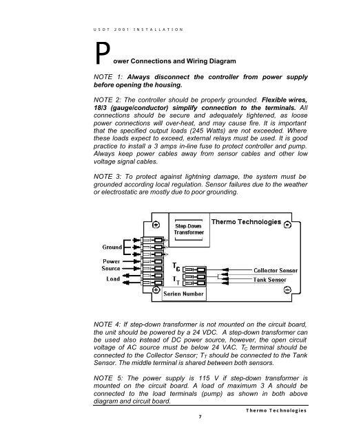
P ower Connections and Wiring Diagram<br />
NOTE 1: Always disconnect the controller from power supply<br />
before opening the housing.<br />
NOTE 2: The controller should be properly grounded. Flexible wires,<br />
18/3 (gauge/conductor) simplify connection to the terminals. All<br />
connections should be secure and adequately tightened, as loose<br />
power connections will over-heat, and may cause fire. It is important<br />
that the specified output loads (245 Watts) are not exceeded. Where<br />
these loads expect to exceed, external relays must be used. It is good<br />
practice to install a 3 amps in-line fuse to protect controller and pump.<br />
Always keep power cables away from sensor cables and other low<br />
voltage signal cables.<br />
NOTE 3: To protect against lightning damage, the system must be<br />
grounded according local regulation. Sensor failures due to the weather<br />
or electrostatic are mostly due to poor grounding.<br />
NOTE 4: If step-down transformer is not mounted on the circuit board,<br />
the unit should be powered by a 24 VDC. A step-down transformer can<br />
be used also instead of DC power source, however, the open circuit<br />
voltage of AC source must be below 24 VAC. T C terminal should be<br />
connected to the Collector Sensor; T T should be connected to the Tank<br />
Sensor. The middle terminal is shared between both sensors.<br />
NOTE 5: The power supply is 115 V if step-down transformer is<br />
mounted on the circuit board. A load of maximum 3 A should be<br />
connected to the load terminals (pump) as shown in both above<br />
diagram and circuit board.<br />
7<br />
Thermo <strong>Technologies</strong>