LASER PRINTER ML-1200 Series
LASER PRINTER ML-1200 Series
LASER PRINTER ML-1200 Series

Create successful ePaper yourself
Turn your PDF publications into a flip-book with our unique Google optimized e-Paper software.
SERVICE<br />
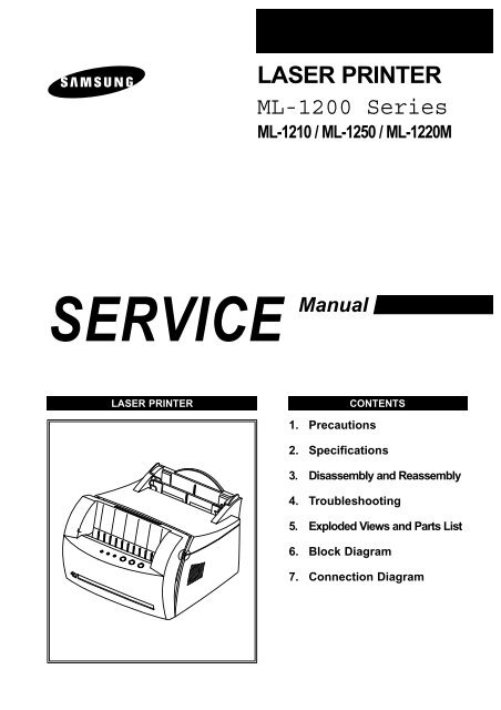
<strong>LASER</strong> <strong>PRINTER</strong><br />
<strong>ML</strong>-<strong>1200</strong> <strong>Series</strong><br />
<strong>ML</strong>-1210 / <strong>ML</strong>-1250 / <strong>ML</strong>-1220M<br />
Manual<br />
<strong>LASER</strong> <strong>PRINTER</strong> CONTENTS<br />
1. Precautions<br />
2. Specifications<br />
3. Disassembly and Reassembly<br />
4. Troubleshooting<br />
5. Exploded Views and Parts List<br />
6. Block Diagram<br />
7. Connection Diagram
This service manual is also provided on the web,<br />
the ITSELF system Samsung Electronics Co., Ltd.<br />
http://itself.sec.samsung.co.kr<br />
© Samsung Electronics Co.,Ltd. October. 2001<br />
Printed in Korea.<br />
VERSION NO. : 2.03 CODE : JC-0051A
This manual is stated and<br />
provided for service description.<br />
All rights reserved. Any parts of the<br />
information in this manual are prohibited<br />
from free duplication, use or translation<br />
without prior written approval except in<br />
cases allowed by the Copyright Act.<br />
Specifications are subject to change without<br />
prior notice.<br />
Samsung Electronics Digital Printing CS Group<br />
Copyright (c) 2001. 5.
1. Precautions<br />
Please read the following carefully to prevent any accidents and not to damage the unit during service.<br />
1-1 Safety Precautions<br />
1. Safety Precautions<br />
There are some electric or machinery parts with<br />
safety related property. If the parts replaced are different<br />
from the original, the safety may not function.<br />
Even if the part could allow higher voltage than that<br />
of the part used, do not replace it and use a regular<br />
product clarified in specifications.<br />
2. Be careful not to leave a switch, a cover or a safety<br />
device out when reinstalling or assembling the product<br />
after repair.<br />
3. Replacing Precautions<br />
Do not change or add parts as you like. You cannot<br />
benefit from such a remodeled product at your will<br />
during the term of guarantee.<br />
4. You must replace overheated or damaged parts or<br />
cords with regular products. Please solve the problem<br />
causing any damage or overheating and troubles<br />
beforehand.<br />
1-2 Precautions on Disassembly and Reassembly<br />
Samsung Electronics<br />
Especially mind the safety on the part with<br />
this mark.<br />
You must use regular parts described in specifications<br />
for the parts inflammable and where the<br />
current can be flown. Otherwise any hazard<br />
such as an electric shock or a fire could occur.<br />
Very careful precautions should be taken when replacing<br />
parts. Before replacing, please check cables because<br />
you cannot put the cables that you removed for replacing<br />
parts into the proper place if you would not make sure of<br />
where they were connected and in which condition.<br />
Please do the following before disassembling for a repair<br />
or replacement of parts.<br />
1. Pull out paper cassette, printer cartridge installed.<br />
Especially careful not to be scratched by the surface of<br />
developer or not to expose them to light.<br />
2. Turn the power switch off.<br />
3. Take out the power plug, printer cable from the printer.<br />
4. Use only the same type of part as original when replacing<br />
parts.<br />
5. Do not force to open or fasten plastic material components.<br />
6. Be careful that small parts such as screws should not<br />
get in the printer.<br />
<strong>LASER</strong> STATEMENT (<strong>LASER</strong>TURVALLISUUS)<br />
Precautions<br />
WARNING : NEVER OPERATE AND SERVICE THE <strong>PRINTER</strong><br />
WITH THE PROTECTIVE COVER REMOVED<br />
FROM <strong>LASER</strong>/SCANNER ASSEMBLY. THE<br />
REFLECTIVE BEAM, ALTHOUGH INVISIBLE, CAN<br />
DAMAGE YOUR EYES.<br />
Class 1 laser product<br />
Luokan 1 laserlaite<br />
Klass 1 laser apparat<br />
Allonpituus 770-795nm<br />
Teho 0.3mW±0.03mW<br />
CAUTION INVISIBLE <strong>LASER</strong> RADIATION WHEN<br />
THIS COVER OPEN. DO NOT OPEN<br />
THIS COVER.<br />
VORSICHT UNSICHTBARE <strong>LASER</strong>STRAHLUNG,<br />
WENN ABDECKUNG GEOFFNET.<br />
NIGHT DEM STRAHL AUSSETZEN.<br />
ATTENTION REYONNEMENT <strong>LASER</strong> INVISIBLE EN CAS<br />
D’OUVERTURE. EXPOSITION DANGERUSE AU<br />
FAISCEAU.<br />
ATTENZIONE RADIAZIONE <strong>LASER</strong> INVISIBLE IN CASO DI<br />
APERTURA. EVITARE L’ESPOSIZONE LA FASCIO.<br />
PRECAUCION REDIACION <strong>LASER</strong> INVISIBLE CUANDO SE<br />
ABRE. EVITAR EXPONERSE AL RAYO.<br />
CAUTION : Avoid exposure to invisible laser radiation when the<br />
development unit is not installed.<br />
7. When disassembling, assembling, also observe small<br />
components are located in place.<br />
8. If you uncover and turn the machine over to replace<br />
some parts, toner or paper particles may contaminate<br />
the LSU window. Protect the LSU window with clean<br />
paper.<br />
Releasing Plastic Latches<br />
Many of parts are held in<br />
place with plastic latches.<br />
The latches break easily :<br />
release them carefully.<br />
To remove such parts,<br />
press the hook end of the<br />
latch away from the part to<br />
which it is latched.<br />
1-1
Precautions<br />
1-3 Tools for Troubleshooting<br />
The following tools are recommended for safe and smooth troubleshooting described in this service manual.<br />
1<br />
2<br />
3<br />
DCU(Diagnostic Control Unit)<br />
Standard: Test equipment to diagnose the Laser<br />
printer supplied by Samsung Electronics.<br />
DVM(Digital Volt Meter)<br />
Standard: Indicates more than 3 digits.<br />
Ground<br />
Electronic Scale<br />
Standard: Equipment to check the weight of consumables(toner<br />
cartridge) supplied by Samsung<br />
Electronics. (The gram unit can be measured.)<br />
Driver<br />
Standard: "-" type, "+" type (M3 long, M3 short,<br />
M2 long, M2 short).<br />
Pinset<br />
Standard: For general home use, small type.<br />
Cotton Swab<br />
Standard: For general home use, for medical service.<br />
Cleaning Equipments a IPA(Isopropyl<br />
Alcohol)dry cloth or a soft stuff neutral<br />
detergent.<br />
Software(Driver) installation CD ROM<br />
Mind your hands not to be touched when<br />
you disassemble and reassemble PBA ASS'Y,<br />
such as the main board, SMPS, HVPS.<br />
1-2 Samsung Electronics<br />
4<br />
5<br />
6<br />
7<br />
8<br />
Note
2. Specifications<br />
Engine<br />
Controller<br />
Paper<br />
Toner<br />
User interface<br />
Samsung Electronics<br />
Speed<br />
Resolution<br />
FROP(Fist Power On Time)<br />
Warm-Up Time<br />
Power Consumption<br />
Dimension<br />
Weight<br />
Processor<br />
Memory<br />
Emulation<br />
Interface<br />
OS Support<br />
N/W<br />
Input<br />
Output<br />
Manual<br />
Media Type<br />
Type<br />
Life<br />
Cartridge<br />
Pick up Roller<br />
Feed Roller<br />
Transfer Roller<br />
Fuser<br />
Key & LED<br />
LCD<br />
Toner Save<br />
Reprint<br />
<strong>ML</strong>-1210 (<strong>ML</strong>-1220M) <strong>ML</strong>-1250<br />
12ppm<br />
600 x 600 dpi <strong>1200</strong> x 600 dpi<br />
Under 12.5 sec<br />
30 sec<br />
25W (Print), 10W (Sleep)<br />
329 x 355 x 231 mm (13” x 14” x 9.1”)<br />
Max 6.5Kg (With Toner Cartridge)<br />
Jupiter 366MHz 6<strong>1200</strong> 66MHz<br />
8MB Equivalent 4MB<br />
SmartGDI PCL6<br />
IEEE1284, USB (<strong>ML</strong>-1220M : USB ONLY)<br />
Windows 95/98/2000/Me/NT,<br />
Linux(Radhat 6.0), iMac(Mac OS 8.0)<br />
External<br />
150 sheets<br />
100 sheets<br />
1 sheet<br />
A4, Letter. Legal, Executive, B5, A5, Folio,<br />
7 3/4(Monarch), #10, DL, C5, C6, B5<br />
Single Cartridge<br />
2,500 sheets<br />
2,500 (Initial : 1,000)<br />
60,000<br />
60,000<br />
60,000<br />
40,000<br />
3Key, 4LEDs<br />
No<br />
YES<br />
YES<br />
Specifications<br />
2-1
3. Disassembly and Reassembly<br />
3-1 Cover Assembly<br />
3-1-1 Front Cover<br />
1. Pull the both side of the cover to open.<br />
2. Remove a screw and remove the stopper that holds<br />
the printer cover.<br />
3. Loosen the right lower part of the cover, then push the<br />
cover in the direction of arrow to loosen the left lower<br />
part.<br />
Samsung Electronics<br />
4. Remove a screw of the front cover PCB and remove<br />
the connector, then remove the cover.<br />
3-1-2 Other Covers<br />
Disassembly and Reassembly<br />
1. Before you remove other covers, you should remove the<br />
Front cover in advance.<br />
2. Rear Cover : Remove the cover in the direction of a .<br />
3. Top Cover : Remove the cover in the direction of b .<br />
4. Side Cover L, R : Remove the cover in the direction of c<br />
.<br />
3-1
Disassembly and Reassembly<br />
3-2 LED Panel PBA<br />
1. Before you remove other covers, you should remove.<br />
• Front Cover (see [3-1 Main Cover])<br />
2. Remove two screws of PCB cover, and widen the<br />
hooks( a b c<br />
) to remove.<br />
3-3 LSU(Laser Scanning Unit)<br />
1. Before you remove LSU, you should remove front<br />
cover, rear cover and top cover.<br />
• Main Cover (see [3-1 Main Cover])<br />
2. Remove three screws securing the LSU.<br />
3. Remove two screws, and remove LED panel.<br />
4. Remove PCB from the PCB cover.<br />
3. Remove two connectors from the LSU, then remove<br />
the LSU.<br />
3-2 Samsung Electronics
3-4 Transfer Roller<br />
1. Open the front cover.<br />
2. Use a proper tool("-" type screwdriver) to pull the one<br />
end of the roller slightly, then take it out.<br />
3-5 Motor Assembly<br />
1. Before you remove the motor assembly, you should<br />
remove:<br />
• Main Cover (see [3-1 Main Cover])<br />
• Shield Engine Assembly<br />
2. Remove five screws securing the motor assembly<br />
and remove a connector from engine board(Engine<br />
board and SMPS board are integrated), then take the<br />
motor assembly out.<br />
Samsung Electronics<br />
Disassembly and Reassembly<br />
3-3
Disassembly and Reassembly<br />
3-6 HVPS Board<br />
1. Before you remove HVPS board, you should remove:<br />
•Main Cover (see [3-1 Main Cover])<br />
2. Remove four screws and a connector from HVPS<br />
board, then take the board out.<br />
Note<br />
When you reassemble the HVPS board, make<br />
sure that five terminals should be put in place.<br />
3-7 Fuser Assembly<br />
1. Before remove fuser assembly, you should remove:<br />
• Main Cover (see [3-1 Main Cover])<br />
2. Remove two ground screws and a connector as illustrated.<br />
Terminal<br />
3. Remove two screws and unplug a fuser assembly<br />
harness. Then use a " - " screwdriver to unlatch the<br />
fuser assembly to remove.<br />
3-4 Samsung Electronics
3-8 Thermostat and Halogen Lamp<br />
1. Remove a screw from the fuser assembly and<br />
remove the thermostat cover, then remove two<br />
screws securing the thermostat.<br />
2. Remove two screws from the fuser assembly, and<br />
take the Heat Roller out.<br />
Samsung Electronics<br />
Disassembly and Reassembly<br />
3. Take the halogen lamp out from the Heat Roller.<br />
Note<br />
When you reassemble the halogen lamp,<br />
handle it with care as it is fragile.<br />
3-5
Disassembly and Reassembly<br />
3-9 SMPS Board<br />
1. Before you remove the SMPS board, you should<br />
remove:<br />
• Main Cover (see [3-1 Main Cover])<br />
2. Remove screws in the order of a b then remove<br />
the shield engine assembly.<br />
a<br />
b<br />
3. Unplug connectors from the main board and connectors<br />
from SMPS, then remove the SMPS. Remove<br />
four screws from SMPS and remove the SMPS<br />
board.<br />
3-6 Samsung Electronics<br />
Note<br />
The Engine board and SMPS board are<br />
integrated in a body.
3-10 Main Board and Sensor Board<br />
1. Before you remove the main board, you should<br />
remove:<br />
• Main Cover (see [3-1 Main Cover])<br />
• SMPS board (see [3-9 SMPS Board])<br />
2. Remove two screws from the main board and unplug<br />
all of connectors, then remove the board.<br />
Samsung Electronics<br />
Main B’d<br />
Disassembly and Reassembly<br />
3. Release four snap-fits securing the insulator engine<br />
board and then remove the insulator.<br />
4. Release four snap-fits securing the sensor board and<br />
then remove the sensor board.<br />
3-7
4. Troubleshooting<br />
4-1 How to use DCU<br />
4-1-1 DCU Setup ......................................Page(4-2)<br />
4-1-2 Code ................................................Page(4-2)<br />
4-1-3 Self Diagnostic Mode......................Page(4-3)<br />
4-1-4 Self Test Button ................................Page(4-4)<br />
4-1-5 Paper Path Layout ...........................Page(4-4)<br />
4-2 The cause and solution of Bad image<br />
4-2-1 Vertical Black Line and Band ..........Page(4-5)<br />
4-2-2 Vertical White Line ...........................Page(4-5)<br />
4-2-3 Horizontal Black Band .....................Page(4-6)<br />
4-2-4 Black/White Spot..............................Page(4-6)<br />
4-2-5 Light Image.......................................Page(4-7)<br />
4-2-6 Dark Image or a Black.....................Page(4-7)<br />
4-2-7 Uneven Density................................Page(4-8)<br />
4-2-8 Background ......................................Page(4-8)<br />
4-2-9 Ghost (1)...........................................Page(4-9)<br />
4-2-10 Ghost (2)..........................................Page(4-9)<br />
4-2-11 Ghost (3) ..........................................Page(4-10)<br />
4-2-12 Ghost (4) .........................................Page(4-10)<br />
4-2-13 Satins on the Face of Page............Page(4-10)<br />
4-2-14 Satins on Back of Page..................Page(4-11)<br />
4-2-15 Blank Page Print out (1) .................Page(4-11)<br />
4-2-16 Blank Page Print out (2) .................Page(4-11)<br />
4-3 The cause and solution of the bad discharge<br />
4-3-1 Wrong Print Position .......................Page(4-12)<br />
4-3-2 JAM 0...............................................Page(4-12)<br />
4-3-3 JAM 1...............................................Page(4-13)<br />
4-3-4 JAM 2...............................................Page(4-13)<br />
4-3-5 Multi-Feeding...................................Page(4-14)<br />
4-3-6 Paper rolled in the fuser .................Page(4-14)<br />
4-3-7 OPC .................................................Page(4-15)<br />
Samsung Electronics<br />
Troubleshooting<br />
4-4 The cause and solution of the malfunction<br />
4-4-1 All LEDs blinking (Fuser Error)........Page(4-16)<br />
4-4-2 All LEDs blinking (SCAN ERROR) .Page(4-16)<br />
4-4-3 Not function of the gear of the fuser due to<br />
melting away.....................................Page(4-17)<br />
4-4-4 Paper Empty.....................................Page(4-17)<br />
4-4-5 Paper Empty without indication.......Page(4-17)<br />
4-4-6 Cover Open......................................Page(4-18)<br />
4-4-7 No lamp on when the cover is open<br />
...........................................................Page(4-18)<br />
4-4-8 Defective motor operation ...............Page(4-19)<br />
4-4-9 No Power..........................................Page(4-19)<br />
4-4-10 Vertical Line Getting Curved .........Page(4-20)<br />
4-5 Toner Cartridge Service<br />
4-5-1 Precautions on Safe-keeping of Toner Cartridge<br />
..........................................................Page(4-21)<br />
4-5-2 Service for the Life of Toner Cartridge<br />
..........................................................Page(4-21)<br />
4-5-3 Service for Judgement of Inferior Expendables<br />
and the Standard of Guarantee .....Page(4-21)<br />
4-5-4 Signs and Measures at Poor toner cartridge<br />
..........................................................Page(4-22)<br />
4-6 The cause and solutions of bad environment<br />
of the software<br />
4-6-1 The printer is not working (1)...........Page(4-25)<br />
4-6-2 The printer is not working (2) .........Page(4-26)<br />
4-6-3 Abnormal Printing.............................Page(4-27)<br />
4-6-4 SPOOL Error ...................................Page(4-28)<br />
4-1
Troubleshooting<br />
4-1 How to use DCU<br />
4-1-1 DCU Setup<br />
You can examine the malfunction of the printer. To perform DCU, open the front discharge cover and leave the connect<br />
the harness wire(10 pin/4 pin) to the CN10(4 pin) of the Main control board.<br />
4-1-2 Code<br />
Connect DCU to the printer and turn the power on. It show 7 LED on the panel and each code tells the function of the<br />
printer.<br />
Normal Code<br />
While printing or warming up, it indicate the position of the paper<br />
61 Warm up The printer is on, the cover is open or close.<br />
00-05 Ready(kind of paper) The printer is ready, the paper is detected when the first paper is printed.<br />
00: Legal , 01: Letter , 02: A4 , 03: EXEC , 04: B5 , 05: Folio<br />
20 Print Start The engine controller received the print order from the video controller.<br />
30 Feed Sensor On The paper is passing out of the Feed Sensor.<br />
40 Feed Sensor off The paper has passed out of the Feed Sensor.<br />
50 Paper Out The paper has passed out of Exit Sensor.<br />
69 Sleep Mode The fuser power turned off to minimize the power consumption.<br />
Error Code<br />
When detecting the malfunction, the printing is stopped to indicate error code.<br />
60, 62, 68 Fuser Error The error in the fuser occurred. There is a short circuit in the thermistor and the<br />
thermostat while printing, Low Temperature Error occurs.<br />
• 60: Open Fuser Error<br />
• 62: Low Heat Error<br />
• 68: Over Heat Error<br />
64 Cover Open The Printer Cover is open or Toner Cartridge not installed.<br />
70 No Paper No paper in the paper cassette.<br />
71 Paper Jam 0 The front part of paper is jammed between pickup unit and Feed sensor.<br />
72 Paper Jam 1 The front part of paper is jammed between the Discharge sensor and Feed sensor.<br />
73 Paper Jam 2 The front part of paper is jammed just after passing through the discharge sensor.<br />
95 LSU Not Ready LSU Scanner Motor not ready or Hsync signal not output.<br />
4-2 Samsung Electronics
4-1-3 Self Diagnostic Mode<br />
If Error code occurs due to malfunction of the printer, perform Self Diagnostic Mode to solve the problem.<br />
Samsung Electronics<br />
Troubleshooting<br />
The printer works only in the self-test mode to solve the malfunction problem.<br />
To enter the self-test mode, turn the power on pressing the buttons of [Down], [Shift] and [Stop] at the same time.<br />
Release the button within 2 or 3 seconds if 78 shows in the DCU. If 00 shows in the DCU, press the button [Up] or [Shift]<br />
to select the self+test , and press the button of [Enter] to operate. To stop, press the button of [shift] and [Enter] together.<br />
00 Main Motor Operating System<br />
Only the main motor is in operation.<br />
01 Main High Voltage On(THV-)<br />
-1550 voltage output by MHV terminal. Caution : High voltage probe should be used.<br />
02 Transfer High Voltage(-)On(THV-)<br />
-1300 voltage output by MHV terminal. Caution : High voltage probe should be used.<br />
03 Transfer High Voltage (+)Reference on (THV +)<br />
1300 voltage output by MHV terminal. Caution : High voltage probe should be used.<br />
04 DEV/supply High Voltage : DEV/Supply High Voltage Test.<br />
The left one of the three LEDs in the self-test panel is on when DEV high voltage Supply high voltage output<br />
by each HV terminal. Press the [Up] button to switch the voltage. The middle and right one of the three LEDs<br />
are on and -530 voltage output by DEV HV terminal. Caution : High voltage probe should be used.<br />
05 LSU Operating System<br />
The scanning motor of LSU is in operation, the right LED of the three buttons on. Press the [Up] button to<br />
Check LD. LD is functioning and the middle button is on. If the LD is normal, all LEDs are on.<br />
06 Pickup clutch on<br />
The Solenoid in the printer is in operation. To stop the operation, Press the button [shift] and [Enter] together.<br />
07 Pempty/PWIDTH/New CRU Sensor Test : Pempty/PWIDTH.HEW CRU sensor test.<br />
If activate the Actuator of the PEMPTY/PWIDTH Sensor, the left and right of the three LEDs are on.<br />
If you install new toner Cartridge in this mode, the right LED is on.<br />
08 Feed & Exit Sensor Test<br />
Test the Feed sensor and Discharge sensor in the same way as '06'.<br />
09 Cover Open Sensor Test<br />
The same way as code '06'.<br />
10 Fuser Test<br />
If the [Enter] button pressed, the right LED is on and temperature of the fuser is up to READY Mode. If the<br />
[Up] button pressed, the middle LED is on and temperature of the fuser is up to Printing Mode.<br />
If you press the button once more, the left LED is on and temperature of the fuser is up to overheat Mode.<br />
11 Hot Burn Test<br />
If the [enter] button pressed, the printer is continuously printing without detection. Turn the power off to stop<br />
operation.<br />
12. Cleaning Mode Print Mode<br />
Print the paper to clean the OPC Drum in the Cartridge.<br />
4-3
Troubleshooting<br />
13. THV(+) TRIGGER. ALL HV<br />
All high voltage output by each HV terminal and LSU and the fan is in operation. In this mode, electronic<br />
resistance of transfer roller and high voltage is detected. If no toner cartridge in the printer, output of THV is<br />
+199V ~ + 2100V.<br />
14. PTL Test<br />
Indicates the PTL LED.<br />
15. Fan Test<br />
Indicates the function of the fan.<br />
4-1-4 Self Test Button<br />
If the Self-Test button pressed, vertical lines are printed.<br />
Turn the power on while pressing this button, '89' shows in the DCU and the printer is warming up. After warming-up the<br />
printer is in READY Mode, and '88' shows in the DCU. In this mode, without any detection, the printer begins<br />
printing(trial printing and data from the PC). It is convenient to use this mode when the engine malfunction is detected in<br />
the control board.<br />
4-1-5 Paper Path Layout<br />
FACE UP<br />
EXIT 2<br />
EXIT 1<br />
FACE DOWN<br />
FUSER<br />
H R/L<br />
Pr R/L<br />
EXIT SENSOR<br />
RECORDED PAPER (100 SHEETS)<br />
CR<br />
OPC<br />
TR<br />
FEED SEN<br />
KNOCK UP<br />
EMPTY SEN<br />
4-4 Samsung Electronics<br />
LSU<br />
CARTRIDGE<br />
DR<br />
SR<br />
PTL<br />
MAIN BOARD<br />
IDLE<br />
PICK UP<br />
FEED<br />
SENSOR BOARD<br />
SMPS<br />
SHIELD SHIELD<br />
MANUAL 1 SHEET<br />
RECORDED PAPER (150 SHEETS)
4-2 The cause and solution of Bad image<br />
4-2-1 Vertical Black Line and Band<br />
• Description<br />
Digital Printer<br />
Digital Printer<br />
Digital Printer<br />
Digital Printer<br />
Digital Printer<br />
4-2-2 Vertical White Line<br />
Samsung Electronics<br />
1. Straight thin black vertical line occurs in the printing.<br />
2. Dark black vertical band occur in the printing.<br />
Check and Cause Solution<br />
1. Damaged develop roller in the Developer<br />
or deformed Doctor-blade.<br />
2. Scratched surface of the discharge roller<br />
in the developer, or heavily accumulated<br />
foreign matters between the discharge<br />
roller and fur transfer roller/ charge roller.<br />
3. Partly depression or deformation on the<br />
surface of the transfer roller.<br />
• Description White vertical voids in the image.<br />
Digital Printer<br />
Digital Printer<br />
Digital Printer<br />
Digital Printer<br />
Digital Printer<br />
Troubleshooting<br />
1. If causes 1 and 2 occur in the developer<br />
cartridge, replace the developer and try to<br />
print out.<br />
2. Replace the transfer roller if occurred as<br />
No. 3.<br />
Check and Cause Solution<br />
1. Foreign matter stuck onto the window of<br />
internal lenses of LSU mirror.<br />
2. Foreign matter or toner particles between<br />
the developer roller and blade.<br />
(In case the life of the developer has<br />
been expired, white lines occur in front of<br />
the image.)<br />
3. It may occur when Burr and foreign substances<br />
are on the window of the developer<br />
frame.<br />
4. If the fuser is defective, voids occur periodically<br />
at the top of a black image.<br />
1. Foreign matter stuck onto the window :<br />
Clean the LSU window with recommended<br />
cleaner(IPA) Clean the window with a<br />
clean cotton swab.<br />
2. Foreign matter in the LSU : Open the<br />
cover of LSU and clean with a cotton<br />
swab on the surface of the reflex mirror.<br />
3. No 3. : Remove the foreign matter and<br />
burr of the exposure window.<br />
4. No. 4. : Open the front cover and check<br />
ribs that corresponds to the position of<br />
the voids. Remove if found.<br />
5. If the problems are not solved, check to<br />
see if the weight of the developer is<br />
below 670g. If so, replace the developer<br />
cartridge.<br />
4-5
Troubleshooting<br />
4-2-3 Horizontal Black Band<br />
• Description<br />
Digital Printer<br />
Digital Printer<br />
Digital Printer<br />
Digital Printer<br />
Digital Printer<br />
4-2-4 Black/White Spot<br />
• Description<br />
Digital Printer<br />
Digital Printer<br />
Digital Printer<br />
Digital Printer<br />
Digital Printer<br />
1. Dark or blurry horizontal stripes occur in the printing periodically.<br />
(They may not occur periodically.)<br />
Check and Cause Solution<br />
1. Bad contacts of the voltage terminals to<br />
developer.<br />
2. The rollers of developer may be stained.<br />
Charge roller = 37 mm<br />
Supply roller = 27 mm<br />
Develop roller = 32 mm<br />
Transfer roller = 47 mm<br />
1. Dark or blurry black spots occur periodically in the printing.<br />
2. White spots occur periodically in the printing.<br />
1. Clean each voltage terminal of the Charge,<br />
Supply, Develop and Transfer roller.<br />
(remove the toner particles and paper particles)<br />
2. Clean the right Gear that has relatively<br />
small gap of the teeth in the OPC.<br />
3. If the malfunction persists, replace the<br />
developer.<br />
Check and Cause Solution<br />
1. If dark or blurry black spots occur periodically,<br />
the rollers in the Developer may be<br />
contaminated with foreign matte or paper<br />
particles.<br />
( Charge roller : 37 mm interval<br />
OPC drum : 75mm interval)<br />
2. If faded areas or voids occur in a black<br />
image at intervals of 75 mm, or black<br />
spots occur elsewhere, the OPC drum<br />
surface is damaged.<br />
3. If a black image is partially broken, the<br />
transfer voltage is abnormal or the transfer<br />
roller's life has expired.<br />
1. Run OPC cleaning Mode Print and run the<br />
Self-test 2 or 3 times.<br />
2. In case of 75mm interval unremovable in 1,<br />
cleanly remove foreign substances stuck on<br />
the OPC location equivalent to black spots<br />
and white spots with a dry duster.<br />
3. The transfer roller guarantees 50,000<br />
sheets printing. If the roller's life is expired,<br />
replace it.<br />
4. In case of 37mm interval unremovable in 1,<br />
take measures as to replace the developer<br />
cartridge and try to print out.<br />
5. Clean the inside of the set against the paper<br />
particles and foreign matter in order not to<br />
cause the trouble.<br />
4-6 Samsung Electronics
4-2-5 Light Image<br />
• Description The printed image is light, with no ghost.<br />
Digital Printer<br />
Digital Printer<br />
Digital Printer<br />
Digital Printer<br />
Digital Printer<br />
4-2-6 Dark Image or a Black<br />
Samsung Electronics<br />
Check and Cause Solution<br />
1. Develop roller is stained when the toner<br />
of developer cartridge is almost consumed.<br />
2. Ambient temperature is below than 10°C.<br />
3. Bad contact caused by the toner stains<br />
between the high voltage terminal in the<br />
HVPS and the one in the set.<br />
4. Abnormal output from the HVPS.<br />
(Run self-test and check 1~4)<br />
• Description The printed image is dark.<br />
Digital Printer<br />
Digital Printer<br />
Digital Printer<br />
Digital Printer<br />
Digital Printer<br />
1. Check if the Toner Save mode is off.<br />
Troubleshooting<br />
2. Replace the developer cartridge and try to<br />
print out.<br />
3. Wait 30 minutes after printer is powered on<br />
before you start printing.<br />
4. Clean up the contaminated area by the<br />
toner.<br />
5. Replace the HVPS if the problems are not<br />
solved by the above four directions.<br />
( Service parts : Figure 11, Chapter 5)<br />
Check and Cause Solution<br />
1. No charge voltage in the engine board.<br />
( Perform DCU diagnostic code 01)<br />
2. Charge voltage is not turned on due to<br />
the bad contacts between power supply<br />
in the side of the Developer and charge<br />
terminal of HVPS.<br />
1. Clean the high voltage charge terminal.<br />
2. Check the state of the connector which<br />
connects the engine board and HVPS.<br />
3. Replace the HVPS if not solved by the<br />
above direction 1 and 2.<br />
4-7
Troubleshooting<br />
4-2-7 Uneven Density<br />
• Description Print density is uneven between left and right.<br />
4-2-8 Background<br />
Check and Cause Solution<br />
1. The pressure force on the left and right<br />
springs of the transfer roller is not even,<br />
the springs are damaged, the transfer<br />
roller is improperly installed, or the transfer<br />
roller bushing or holder is damaged.<br />
2. The toner level is not even on the developer<br />
roller due to the bad blade.<br />
• Description Light dark background appears in whole area of the printing.<br />
Digital Printer<br />
Digital Printer<br />
Digital Printer<br />
Digital Printer<br />
Digital Printer<br />
1. Replace both the left and right Spring<br />
Holder.<br />
2. Occur in the developer cartridge, replace<br />
the developer and try to print out.<br />
Check and Cause Solution<br />
1. Recycled recording paper has been<br />
used.<br />
2. The life of the Developer has expired.<br />
(The weight at the expiration of the<br />
developer's life: 800 ± 20g)<br />
3. The up-to-down movement of the transfer<br />
roller is swift?<br />
4. The HVPS is normal?<br />
(Perform DCU diagnostic code 01~04)<br />
1. B/S is not guaranteed when using recycled<br />
paper.<br />
2. Replace the Developer that has expired.<br />
3. Clean the busing part of the transfer roller.<br />
4. Replace the Developer if not solved by the<br />
above direction 1~3.<br />
4-8 Samsung Electronics
4-2-9 Ghost (1)<br />
• Description Ghost occurs at 75 mm intervals of the OPC drum in the whole printing.<br />
Digital Printer<br />
Digital Printer<br />
Digital Printer<br />
Digital Printer<br />
Digital Printer<br />
Digital Printer<br />
4-2-10 Ghost (2)<br />
• Description<br />
Digital Printer<br />
Digital Printer<br />
Digital Printer<br />
Digital Printer<br />
Digital Printer<br />
Digital Printer<br />
Samsung Electronics<br />
75mm<br />
Check and Cause Solution<br />
1. Bad contacts caused by contamination<br />
from toner particles between high voltage<br />
terminal in the main body and the electrode<br />
of the Developer.<br />
2. Bad contacts caused by contamination<br />
from toner particles between high voltage<br />
terminal in the main body and the one in<br />
the HVPS board.<br />
3. The life of developer is expired.<br />
4. Transfer roller lifetime(50,000 sheets) has<br />
expired.<br />
5. Abnormal low temperature(below 10°C).<br />
Ghost occurs at 75 mm intervals of the OPC drum in the whole printing.<br />
(When printing on card stock or transparencies using manual feeder)<br />
75mm<br />
Troubleshooting<br />
1. Clean the terminals when contaminated by<br />
toner particles.<br />
2. Occur in the developer cartridge, replace<br />
the developer and try to print out.<br />
3. Replace the engine board if not solved by<br />
the above directions 1-2.<br />
(Service Parts : Figure 9 , chapter 5)<br />
4. If not solved by the direction 3, check the<br />
transfer roller lifetime and replace it.<br />
(Service Parts : Figure 8-2 , chapter 5)<br />
5. Wait about 1 hour after power on before<br />
using printer.<br />
Check and Cause Solution<br />
When printing on card stock thicker than normal<br />
paper or transparencies such as OHP,<br />
higher transfer voltage is required.<br />
Select 'Thick Mode' on paper type menu from<br />
the software application and after using returning<br />
to the original mode is recommended.<br />
4-9
Troubleshooting<br />
4-2-11 Ghost (3)<br />
• Description White ghost occurs in the black image printing at 32mm intervals.<br />
Digital<br />
Digital<br />
Printer<br />
Printer<br />
Digital<br />
Digital<br />
Printer<br />
Printer<br />
Digital<br />
Digital<br />
Printer<br />
Printer<br />
4-2-12 Ghost (4)<br />
32mm<br />
Check and Cause Solution<br />
1. The life of the developer may be expired.<br />
2. The abnormal voltage and bad contact of<br />
the terminal of the supply roller roller.<br />
• Description Ghost occurs at 47mm intervals.<br />
Digital Printer<br />
Digital Printer<br />
Digital Printer<br />
Digital Printer<br />
Digital Printer<br />
Digital Printer<br />
47mm<br />
4-2-13 Satins on the Face of Page<br />
1. Occur in the developer cartridge, replace<br />
the developer and try to print out.<br />
2. Check the approved voltage of the supply<br />
roller and contact of the terminal and adjust<br />
if necessary.<br />
Check and Cause Solution<br />
The temperature of the fuser is maintained<br />
high.<br />
• Description The background on the face of the printed page is stained.<br />
Digital Printer<br />
Digital Printer<br />
Digital Printer<br />
Digital Printer<br />
Digital Printer<br />
1. Disassemble the fuser and remove the<br />
contaminated toner particles on the roller<br />
and clean the foreign matter between<br />
Thermistor and Heat roller.<br />
( Caution: can be deformed)<br />
Check and Cause Solution<br />
1. Toner leakage due to improperly sealed<br />
developer.<br />
2. If the transfer roller is contaminated, satins<br />
on the face of page will occur.<br />
1. Replace the developer cartridge.<br />
2. If the transfer roller is contaminated, run PC<br />
Cleaning Mode Print 2 or 3 times.<br />
And perform Self-Test 2 or 3 times to<br />
remove contamination.<br />
4-10 Samsung Electronics
4-2-14 Satins on Back of Page<br />
• Description The back of the page is stained at 47mm intervals.<br />
Digital<br />
Digital Pri<br />
Digital Printer<br />
Digital Printer<br />
Digital Printer<br />
4-2-15 Blank Page Print out (1)<br />
• Description Blank page is printed.<br />
Digital Printer<br />
Digital Printer<br />
Digital Printer<br />
Digital Printer<br />
Digital Printer<br />
4-2-16 Blank Page Print out (2)<br />
• Description<br />
Samsung Electronics<br />
Check and Cause Solution<br />
1. Transfer roller is contaminated.<br />
2. Pressure roller is contaminated.<br />
Troubleshooting<br />
1. Perform the OPC Cleaning Mode Print 2 or<br />
3 times. Run Self-Test to remove the contamination<br />
of the transfer roller.<br />
2. Replace the transfer roller if contaminated<br />
severely.<br />
3. Disassemble the fuser and clean the<br />
H/R(Heat Roller) and P/R(Pressure roller).<br />
And check the area between H/R and<br />
Thermistor. If contaminated, clean the area<br />
not to be deformed.<br />
Check and Cause Solution<br />
Bad ground contacts in OPC and/or developer.<br />
1. Blank page is printed.<br />
2. One or several blank pages are printed.<br />
3. When the printer turns on, several blank pages print.<br />
Remove contamination of the terminals of the<br />
developer and the unit.<br />
Check and Cause Solution<br />
1. Bad ground contacts in OPC and/or<br />
developer.<br />
2. Abnormal solenoid.<br />
1. Remove contamination of the terminals of<br />
the developer.<br />
2. Perform the engine self test using DCU to check<br />
if the Solenoid is normal.(refer to code 06)<br />
3. If not solved by the above directions 1-2,<br />
Replace the engine board.<br />
(Service Parts : Figure 9 , chapter 5)<br />
4. Turn the power off, delete the data of PC<br />
and try printing again.<br />
4-11
Troubleshooting<br />
4-3 The cause and solution of the bad discharge<br />
4-3-1 Wrong Print Position<br />
• Description Printing begins at wrong position on the paper.<br />
Check and Cause Solution<br />
Wrong sense time caused by defective feed sensor<br />
actuator.<br />
4-3-2 JAM 0<br />
• Description<br />
EXIT 2<br />
EXIT 1<br />
EXIT SENSOR<br />
CARTRIDGE<br />
LSU<br />
FEED SEN<br />
1. Paper is not exited from the cassette.<br />
2. Jam-0 occurs if the paper feeds into the printer.<br />
PICK UP<br />
JAM 0<br />
Replace the defective actuator<br />
(Service Parts : Figure 8-16 , chapter 5)<br />
Check and Cause Solution<br />
1. Check the Solenoid by using DCU<br />
diagnostic mode 06.<br />
2. Check if the pad is loose due to bad<br />
sealing of the side-pad.<br />
3. Check the surface of the roller-pickup<br />
for foreign matter.<br />
4. If continuous clusters occur, check<br />
whether the assembly slot between<br />
shaft-pickup and housing-pickup<br />
become open or is broken away.<br />
5. If the paper feeds into the printer<br />
rand Jam 0 occurs, perform DCU to<br />
check feed-sensor of the sensor<br />
board.<br />
1. Replace the solenoid. (Service Parts :<br />
Figure 8-11 , chapter 5)<br />
2. Replace the side-pad Assembly L or<br />
R, if necessary.<br />
(Service Parts : Figure 8-13 , 8-14,<br />
chapter 5)<br />
3. Clean with soft cloth dampened with<br />
IPA(Isopropyl Alcohol) or water.<br />
4. Replace the Housing-Pickup and/or<br />
Shaft-Pickup.<br />
(Service Parts : Figure 8-135, 8-12, chapter 5)<br />
4-12 Samsung Electronics
4-3-3 JAM 1<br />
4-3-4 JAM 2<br />
• Description<br />
EXIT 2<br />
EXIT 1<br />
• Description<br />
EXIT 2<br />
EXIT 1<br />
JAM 2<br />
EXIT SENSOR<br />
EXIT SENSOR<br />
CARTRIDGE<br />
JAM 1<br />
CARTRIDGE<br />
LSU<br />
FEED SEN<br />
LSU<br />
FEED SEN<br />
Samsung Electronics<br />
Troubleshooting<br />
1. Recording paper is jammed in front of or inside the fuser.<br />
2. Recording paper is stuck in the discharge roller and in the fuser just after passing through the<br />
Actuator-Feed.<br />
PICK UP<br />
FEED<br />
1. Recording paper is jammed in front of or inside the fuser.<br />
2. Recording paper is stuck in the discharge roller and in the fuser just after passing through the<br />
Actuator-Feed.<br />
PICK UP<br />
Check and Cause Solution<br />
1. If the recording paper is jammed in<br />
front of or inside the fuser.<br />
(Perform DCU diagnostic code of)<br />
2. If the recording paper is stuck in the<br />
discharge roller and the fuser just<br />
after passing through the Actuator-<br />
Feed, Feed Actuator may be defective.<br />
Check and Cause Solution<br />
1. If the paper is completely fed out of<br />
the printer, but Jam 2 occurs : Exit<br />
sensor is defective.<br />
• After the paper is completely discharged,<br />
actuator Exit should return<br />
to the original position to shut the<br />
photo-sensor. Sometimes it takes<br />
longer hour than it should and does<br />
not return.<br />
2. If the paper is rolled in the Fuser Roller:<br />
• This occurs when a Guide claw is<br />
broken away or transformed.<br />
• It occurs when the Spring of a Guide<br />
claw is broken away or transformed.<br />
• It occurs when the Heat-Roller or<br />
Pressure-Roller is seriously contaminated<br />
with the toner.<br />
3. Paper is accordion in the fuser.<br />
1. Replace the SMPS. (Service Parts :<br />
Figure 10, chapter 5)<br />
2. Reassemble the Actuator-Feed and<br />
Spring-Actuator if the returning is bad.<br />
1. Check if the exit sensor actuator is<br />
defective.<br />
• Check if the actuator exit is unformed<br />
(Check if the lever part is unformed<br />
in shape).<br />
• Check whether burrs occur in the<br />
assembly part of the actuator exit or<br />
not and if the actuator is smoothly<br />
operated.<br />
• Check if foreign matters and wire get<br />
caught in the actuator exit's operation.<br />
2. If the paper is stuck in the fuser : disassemble<br />
the fuser and remove the<br />
jammed paper, and clean the surface<br />
of the pressure roller with dry gauze.<br />
3. Remove the jammed paper after disassembling<br />
the fuser : Clean the surface<br />
of the pressure roller with dry gauze.<br />
• Remove the toner particles stained<br />
on the rib.<br />
• Check the assemblage and performance<br />
of the exit.<br />
4-13
Troubleshooting<br />
4-3-5 Multi-Feeding<br />
• Description Multiple sheets of paper are fed at once.<br />
Check and Cause Solution<br />
1. Solenoid malfunction(the solenoid does not work<br />
properly): Perform DCU mode : solenoid check 06.<br />
2. Pad-Friction is contaminated with foreign matter.(oil...)<br />
3. The face of paper is blended.<br />
4-3-6 Paper rolled in the fuser<br />
1. Replace the solenoid if necessary.<br />
(Service Parts : Figure 13, chapter 5)<br />
2. Clean the pad friction with soft clothe dampened<br />
with IPA(Isopropyl Alcohol).<br />
3. Use the smooth paper.<br />
• Description If contaminated at intervals of 57mm on the back of a paper.<br />
1. Contamination of the pressure roller.<br />
(Background, Hot off set)<br />
Check and Cause Solution<br />
1. Disassemble the fuser, clean the area between the<br />
Heat-roller and Thermistor and remove the foreign<br />
matter of the pressure roller.<br />
2. If background appears badly in the printing, fix it by<br />
referring to the solutions for background.<br />
(See 4-2-8 Background)<br />
4-14 Samsung Electronics
4-3-7 OPC<br />
• Description Paper is rolled up in the OPC.<br />
1. Paper is too much thin.<br />
2. The face of paper is curled.<br />
Samsung Electronics<br />
Check and Cause Solution<br />
1. Recommend to use normal paper.<br />
Troubleshooting<br />
2. How to remove the rolled paper in the OPC.<br />
• Remove the paper while turning the OPC against<br />
the ongoing direction.<br />
• Clean fingerprints on the OPC softly with soft<br />
cloth dampened with IPA(Isopropyl Alcohol) or tissue.<br />
4-15
Troubleshooting<br />
4-4 The cause and solution of the malfunction<br />
4-4-1 All LEDs blinking (Fuser Error)<br />
• Description<br />
1. All the lamps on the operator panel blink.<br />
2. Gear of the fuser does not work and breaks away melt away.<br />
When printing, motor breaks away from its place due to defective fuser gear.<br />
Check and Cause Solution<br />
1. Check if the thermostat, AC wire and Heat Lamp is<br />
open.<br />
2. Check if the thermistor sensor is in place.<br />
3. Check if the heat lamp works properly.<br />
4. Check if the overheat circuit works properly.<br />
5. The fuser gear is defective due to melting away.<br />
4-4-2 All LEDs blinking (Scan Error)<br />
• Description 1. All lamps on the operator panel blink.<br />
1. If the thermostat is open replace the fuser and<br />
check following items.<br />
2. If the thermistor sensor device is located deep in the<br />
sponge, replace the fuser.<br />
3. Check if the circuit of overheat mode works properly.<br />
4. Run DCU mode : Perform DCU diagnostic code 10.<br />
Check and Cause Solution<br />
DCU Mode : Perform DCU diagnostic code 05. If the DCU<br />
error code 95 is displayed, replace LSU.<br />
Replace LSU.<br />
(Service Parts : Figure 13, chapter 5)<br />
If you cannot solve the problem after you replace LSU,<br />
replace the main board.<br />
4-16 Samsung Electronics
4-4-3 Not function of the gear of the fuser due to melting away<br />
• Description The motor breaks away from its place due to gear melting away.<br />
Samsung Electronics<br />
Check and Cause Solution<br />
DCU Mode : Check if the Error States '60' '62' '68' occur.<br />
Check the operation of Fuser Erasing Lamp On/Off with<br />
the Error Code Check -10-.<br />
4-4-4 Paper Empty<br />
1. Replace the Fuser.<br />
(Service Parts : Figure 8-4, Chapter 5)<br />
2. Replace the Main Control board.<br />
(Service Parts : Figure 9, Chapter 5)<br />
• Description The paper lamp on the operator panel is on even when paper is loaded in the cassette.<br />
Check and Cause Solution<br />
1. Bending or deformation of the actuator of the paper sensor.<br />
2. The function of the sensor board is defective Perform<br />
DCU mode: Perform DCU diagnostic code 8.<br />
4-4-5 Paper Empty without indication<br />
1. Replace the defective actuator.<br />
(Service Parts : Figure 8-17, Chapter 5)<br />
2. Replace the sensor board.<br />
(Service Parts : Figure 8-10, Chapter 5)<br />
• Description The paper lamp on the operator panel does not come on when the paper cassette is empty.<br />
Check and Cause Solution<br />
1. Bending or deformation of the actuator of the paper sensor.<br />
2. The function of the sensor board is defective Perform.<br />
DCU mode : Perform DCU diagnostic code 8.<br />
1. Replace the defective actuator.<br />
(Service Parts : Figure 8-17, chapter 5)<br />
2. Replace the sensor board.<br />
(Service Parts : Figure 8-10, chapter 5)<br />
Troubleshooting<br />
4-17
Troubleshooting<br />
4-4-6 Cover Open<br />
• Description The ERROR lamp is on even when the print cover is closed.<br />
Check and Cause Solution<br />
1. The hook lever in the top cover may be defective.<br />
2. Check the connector and circuit of the cover switch<br />
department in the Main Control board. Perform DCU<br />
mode : If Error state '64' occurs, Check the related codes<br />
of the Cover Open Error.<br />
Hook Lever<br />
4-4-7 No lamp on when the cover is open<br />
1. Replace the hook lever, if defective.<br />
(Service Parts : Figure 1, chapter 5)<br />
2. Check the insertion of the Cover Open Sensor<br />
Connect.<br />
3. Replace the Main Control board or Cover Open<br />
Sensor.<br />
(Service Parts : Figure 9, chapter 5)<br />
• Description The ERROR lamp does not come on even when the printer cover is open<br />
Check and Cause Solution<br />
1. Check the connector(CN8) and circuit of the cover switch<br />
department in the Main Control board. Perform DCU<br />
mode : If Error state '64' occurs, Check the related codes<br />
of the Cover Open Error<br />
1. Check the insertion of the Cover Open Sensor<br />
Connect.<br />
2. Replace the Main Control board or Cover Open<br />
Sensor.<br />
(Service Parts : Figure 9, chapter 5)<br />
4-18 Samsung Electronics
4-4-9 Defective motor operation<br />
Samsung Electronics<br />
Troubleshooting<br />
• Description Main motor is not driving when printing, and paper does not feed into the printer, resulting 'Jam 0'.<br />
Check and Cause Solution<br />
1. Motor harness or sub PCB may be defective.<br />
2. Perform DCU diagnostic code 00 and Check the motor<br />
operation.<br />
4-4-10 No Power<br />
1. Check the motor harness, replace it, if defective.<br />
(Service Parts : Figure 12, chapter 5)<br />
2. Replace the SMPS, if necessary.<br />
(Service Parts : Figure 10, chapter 5)<br />
• Description When system power is turned on, all lamps on the operator panel do not come on.<br />
Check and Cause Solution<br />
1. Check if the power input and SMPS output are normal.<br />
2. Check the inferiority of LED-Panel on the front-cover if<br />
the LED of Panel does not appear after normal warmingup.<br />
1. Replace the power supply cord or SMPS.<br />
(Service Parts : Figure 10, chapter 5)<br />
2. Replace the control board.<br />
(Service Parts : Figure 9, chapter 5)<br />
3. Replace the LED-panel.<br />
(Service Parts : Figure 1-1, chapter 5)<br />
4-19
Troubleshooting<br />
4-4-11 Vertical Line Getting Curved<br />
• Description When printing, vertical line gets curved.<br />
Check and Cause Solution<br />
1. If the supply of +24v is unstable in the Main Control board<br />
linking with LSU, check drive by DCU Mode: LSU Check<br />
-05- LSU Motor on.<br />
1. Replace LSU.<br />
(Service Parts : Figure 13, chapter 5)<br />
2. Replace the Main Control board.<br />
(Service Parts : Figure 9, chapter 5)<br />
4-20 Samsung Electronics
4-5 Toner Cartridge Service<br />
It is not guaranteed for the default caused by using other toner cartridge other than the cartridge supplied by the<br />
Samsung Electronic or caused by non-licensed refill production.<br />
4-5-1 Precautions on Safe-keeping of Toner Cartridge<br />
Excessive exposure to direct light more than a few minutes may cause damage to the cartridge.<br />
4-5-2 Service for the Life of Toner Cartridge<br />
Samsung Electronics<br />
Troubleshooting<br />
If the printed image is light due to the life of the toner, you can temporarily improve the print quality by redistributing the<br />
toner(Shake the toner cartridge), however, you should replace the toner cartridge to solve the problem thoroughly.<br />
4-5-3 Service for Judgement of Inferior Expendables and the Standard of Guarantee<br />
Please refer to User's Manual or Instructions on Fax/Printer Expendables SVC for the judgement of inferior expendables<br />
and the standard of guarantee besides this service manual.<br />
4-21
Troubleshooting<br />
4-5-4 Signs and Measures at Poor toner cartridge<br />
Fault Signs Cause & Check Solution<br />
Light image and<br />
partially blank<br />
image<br />
(The life is ended.)<br />
Digital Printer<br />
Digital Printer<br />
Digital Printer<br />
Digital Printer<br />
Digital Printer<br />
Toner<br />
Contamination<br />
• The printed image<br />
is light or unclean<br />
and untidy.<br />
• Some part of the<br />
image is not printed.<br />
• Periodically a noise<br />
as "tick tick" occurs.<br />
• Toner is fallen on<br />
the papers periodically.<br />
• Contaminated with<br />
toner on prints partly<br />
or over the whole<br />
surface.<br />
1. If the image is light or unclean<br />
and untidy printed image -<br />
Shake the developer and<br />
then recheck.<br />
(1)NG: Check the weight of the<br />
developer<br />
(2)OK: Lack of toner, so the life<br />
is nearly closed.<br />
2. Some part of image is not<br />
printed - Shake the developer<br />
and then recheck.<br />
(1)NG: Check the weight of the<br />
developer and clean<br />
the LSU window with a<br />
cotton swab, then<br />
recheck.<br />
(2)OK: Lack of toner, so the life<br />
is nearly closed.<br />
3. Periodically a noise as "tick<br />
tick" occurs - Measure the<br />
cycle and the weight of the<br />
developer.<br />
4. White vertical stripes on the<br />
whole screen or partly :<br />
Check the weight of the<br />
developer.<br />
1. Toner is fallen on the paper<br />
periodically.<br />
(1)Check the cycle of the<br />
falling of the toner.<br />
(2)Check the appearance of<br />
both ends of the developer<br />
OPC drum.<br />
2.The center of the printed matter<br />
is contaminated with toner.<br />
(1)Check whether foreign substances<br />
or toner are stuck<br />
to the terminal (contact<br />
point) of the developer.<br />
(2)Check whether the state of<br />
the terminal assembly is<br />
normal.<br />
1. All of 1, 2, 3 above-<br />
(1)The weight of the developer<br />
ended: 800g ± 20g<br />
(2)If it become better by shaking,<br />
replace with a new developer<br />
after 50-100 sheets in the closing<br />
state of the life span.<br />
2. In case of 2-<br />
If it becomes better after cleaning<br />
the LSU window, then the<br />
developer is normal.<br />
(Because of foreign substance<br />
on the LSU window, the image<br />
has not been printed partly.)<br />
3. In case of 3-<br />
If the cycle of noise is about 2<br />
seconds, the toner inside the<br />
developer has been nearly<br />
exhausted.( Purchase and<br />
replace with a new developer<br />
after using about 200 sheets at<br />
the point of occurrence)<br />
4. In case of 3-<br />
This is a phenomenon caused<br />
by lack of toner, so replace with<br />
a new developer.<br />
1. If both ends of the OPC drum<br />
are contaminated with toner:<br />
Check the life of the developer.<br />
(In case of less than 820g, the<br />
life may be expired.)<br />
2. Check whether it could be recycled.<br />
3. If it cannot be recycled:<br />
Replace the developer.<br />
4-22 Samsung Electronics
Fault Signs Cause & Check Solution<br />
White Black spot<br />
Digital Printer<br />
Digital Printer<br />
Digital Printer<br />
Digital Printer<br />
Digital Printer<br />
Recycled product<br />
Samsung Electronics<br />
• Light or dark black<br />
dots on the image<br />
occur periodically.<br />
• White spots occur<br />
in the image periodically.<br />
• Poor appearance of<br />
the developer.<br />
• Unclean and rough<br />
printouts.<br />
• Bad background in<br />
the image.<br />
1. If light or dark periodical black<br />
dots occur, this is because the<br />
developer rollers are contaminated<br />
with foreign substance<br />
or paper particles.<br />
(1)35mm interval : Charged<br />
roller<br />
(2)75mm interval : OPC cycle<br />
2. If white spots occur in a black<br />
image at intervals of 75mm, or<br />
black spots occur elsewhere,<br />
the OPC drum is damaged or<br />
foreign substance is stuck to<br />
the surface.<br />
3. If a black and white or graphic<br />
image is partially broken at<br />
irregular intervals, the transfer<br />
roller's life has been expired or<br />
the transfer voltage is abnormal.<br />
1. Poor appearance of the developer.<br />
(1)Check the damage to label<br />
and whether different materials<br />
are used.<br />
(2)Check the appearance of<br />
parts of the developer, such<br />
as frame, hopper.<br />
2. Unclean and rough printouts.<br />
(1)Check whether foreign substance<br />
or toner are stuck to<br />
the terminal (contact point) of<br />
the developer.<br />
(2)Check whether the state of<br />
the terminal assembly is normal.<br />
Troubleshooting<br />
1. In case of 1 above -<br />
Run OPC Cleaning Mode Print<br />
4-5 times repeatedly to remove.<br />
Especially check foreign substance<br />
on the OPC surface, then<br />
remove them with a clean gauze<br />
moistened with IPA(Isopropyl<br />
Alcohol) not to damage OPC if<br />
necessary.<br />
Never use usual alcohol.<br />
2. In case of 2<br />
If they are not disappeared by<br />
running OPC Cleaning Mode<br />
Print 4-5 times.<br />
: at intervals of 37mm - Replace<br />
the developer.<br />
: at intervals of 75mm - Remove<br />
foreign substance.<br />
: Broken image - Replace the<br />
developer according to carelessness.<br />
3. In case of 3 - Exchange the<br />
transfer roller because the life of<br />
the transfer roller in use has been<br />
expired. (Check the transfer voltage<br />
and readjust if different.)<br />
1. In case of 1 -<br />
(1)If there is an evidence of disassembling<br />
the developer.<br />
(2)If materials other than normal<br />
parts of the developer are<br />
added or substituted.<br />
2. In case of 2 - If there are any<br />
abnormals in connection with the<br />
situation of 1.<br />
(1)It occurs when the developer<br />
is recycled over 2 times.<br />
(2)If toner nearly being expired<br />
are collected to use, it is<br />
judged as the recycled developer.<br />
4-23
Troubleshooting<br />
Fault Signs Cause & Check Solution<br />
Ghost & Image<br />
Contamination<br />
• The printed image<br />
is too light or dark,<br />
or partially contaminated<br />
black.<br />
• Totally contaminatedblack.<br />
(Black image printed<br />
out)<br />
• The density of printouts<br />
is too dark and<br />
ghost occurs.<br />
1. The printed image is too light<br />
or dark, or partially contaminated<br />
black.<br />
(1)Check whether foreign substance<br />
or toner are stuck to<br />
the terminal(point of contact)<br />
of the developer.<br />
(2)Check whether the terminal<br />
assembly is normal.<br />
2. Totally contaminated black.<br />
(Black image printed out)<br />
(1)Check whether foreign substances<br />
are stuck to the terminal(point<br />
of contact) of the<br />
developer and the state of<br />
assembly.<br />
(Especially check the<br />
charged roller terminal.)<br />
3. The printed image is dark and<br />
ghost occurs.<br />
(1)Check foreign substance<br />
attached to the terminal<br />
(point of contact) of the<br />
developer and the state of<br />
assembly.<br />
(Especially check the developing<br />
roller terminal.)<br />
1. All of 1, 2, 3 above<br />
(1)Remove toner and foreign substances<br />
adhered to the contact<br />
point of the developer.<br />
(2)The contact point of the unit<br />
facing that of the developer<br />
also must be cleaned.<br />
(3)If the terminal assembly is<br />
unsafe:<br />
• Fully stick the terminal to or<br />
reassemble it after disassembling.<br />
• Disassemble the side plate and<br />
push the terminal to be stuck,<br />
then reassemble it.<br />
2. In case of 2<br />
It is a phenomenon when the<br />
OPC drum of the developer is not<br />
electrically charged. Clean the<br />
terminals of the charged roller,<br />
then recheck it.<br />
3. In case of 3<br />
It is a phenomenon as the developing<br />
bias voltage of the developer.<br />
Clean the terminals of the<br />
developing roller, then recheck it.<br />
4-24 Samsung Electronics
4-6 The cause and solutions of bad environment of the software<br />
4-6-1 The printer is not working (1)<br />
• Description While Power turned on, the printer is not working in the printing mode.<br />
Samsung Electronics<br />
Check and Cause Solution<br />
1. Run Self-Test Mode: Turn the power on while pressing<br />
the test printing button for 2 or 3 seconds before printing<br />
works.<br />
2. Check if the PC and the printer is properly connected<br />
and the toner cartridge installed.<br />
3. Printing is nor working in the Windows.<br />
4. Check if the printer cable is directly connected to peripheral<br />
devices<br />
Troubleshooting<br />
1.Check the power of the printer and perform the Self-<br />
Test. If the test printing works, that means no problems<br />
in the printer itself. If the test printing does not<br />
work, that means bad functioning of the printer(not<br />
because of software). Perform DCU to check the<br />
Error Status.<br />
2. Replace the printer cable. If the problems not solved<br />
even after the cable replaced, check the amount of<br />
the remaining tone.<br />
(refer to Toner Cartridge Service 4-5)<br />
3. Check if the connection between PC and printer port<br />
is proper. If you use windows, check if the printer driver<br />
in the controller is set up. If the printer driver is<br />
properly set up, check in which program the printing<br />
is not working. The best way to find out is to open the<br />
memo pad to check the function of printing. If it is not<br />
working in a certain program, adjust the setup the<br />
program requires. Sometimes, the printout is normal<br />
within the Windows basic programs, but it's not working<br />
in a particular program. In such case, install the<br />
new driver again. If not working in the Windows basic<br />
program, Check the setup of the port of CMOS is on<br />
ECP. And check the address of IRQ 7 and 378<br />
4. If the scanner needs to be connected to the printer,<br />
first the remove the scanner from the PC to see if the<br />
printer is properly working alone.<br />
4-25
Troubleshooting<br />
4-6-2 The printer is not working (2)<br />
• Description<br />
1. Secure more space of the hard disk.<br />
After receiving the printing order, no response at all or the low speed of printing<br />
occurs due to wrong setup of the environment rather than malfunction of the printer itself.<br />
Check and Cause Solution<br />
2. Printing error occurs even if there is enough space in<br />
the hard disk.<br />
3. Check the parallel-port-related items in the CMOS<br />
Setup.<br />
4. Reboot the system to print.<br />
1. Not working with the message 'insufficient printer<br />
memory' means hard disk space problem rather than<br />
the RAM problem. In this case, provide more space<br />
for the hard disk. Secure more space using the disk<br />
utilities program.<br />
2. The connection of the cable and printer port is not<br />
proper. Check if the connection is properly done and<br />
if the parallel port in CMOS is rightly set up.<br />
3. As a printer port, Select ECP or SPP among<br />
SPP(Normal), ECP, and EPP modes(increase printing<br />
speed) SPP normal mode support 8-bit data<br />
transfer, while ECP Mode transfer the 12-bit data.<br />
4. If the regular font is not printing, the cable or the<br />
printer driver may be defective.<br />
Turn the PC and printer off, and reboot the system<br />
to print again. If not solved, double-click the printer in<br />
my computer If the regular fonts are not printed this<br />
time again. the cable must be defective so replace<br />
the cable with new one.<br />
4-26 Samsung Electronics
4-6-3 Abnormal Printing<br />
• Description<br />
Samsung Electronics<br />
Troubleshooting<br />
The printing is not working properly even when the cable has no problem.<br />
(even after the cable is replaced)<br />
If the printer won't work at all or the strange fonts are repeated, the printer driver may be defective<br />
or wrong setup in the CMOS Setup.<br />
Check and Cause Solution<br />
1. Set up the parallel port in the CMOS SETUP.<br />
2. Printer Driver Error.<br />
3. Error message from insufficient memory.<br />
(The printing job sometimes stops or due to insufficient<br />
virtual memory, but it actually comes from the insufficient<br />
space of the hard disk.)<br />
1. Select SPP(Normal) or ECP LPT Port the among<br />
ECP, EPP or SPP in the CMOS Setup.<br />
2. Check the printer in My Computer.(to see if the<br />
printer driver is compatible to the present driver or<br />
delete the old driver, if defective and reinstall the new<br />
driver)<br />
3. Delete the unnecessary files to secure enough<br />
space of the hard disk and start printing job again.<br />
4-27
Troubleshooting<br />
4-6-4 SPOOL Error<br />
• Description<br />
To spool which stands for "simultaneous peripheral operations online" a computer document or<br />
task list (or "job") is to read it in and store it, usually on a hard disk or larger storage medium so<br />
that it can be printed or otherwise processed at a more convenient time (for example, when a<br />
printer is finished printing its current document).<br />
Check and Cause Solution<br />
1. Insufficient space of the hard disk in the directory<br />
assigned for the basic spool.<br />
2. If the previous printing error not solved.<br />
3. When expected to collide with other program.<br />
4. When an application program or the printer driver is<br />
damaged.<br />
5. When some files related to OS are damaged or virus<br />
infected.<br />
6. Memory is less than suggested one.<br />
How to delete the data in the spool manager.<br />
1. Delete the unnecessary files to provide more space<br />
to start printing job.<br />
2. If there are some files with the extension name of<br />
****.jnl, Delete them and Reboot the Windows to<br />
restart printing job.<br />
3. Shut down all other programs except the current<br />
one, if possible.<br />
4. Delete the printer driver completely and reinstall it.<br />
5 After rebooting the computer, check for viruses,<br />
restore the damaged files and reinstall the program<br />
to do the printing job.<br />
6. Add up enough memory to the PC.<br />
In the spool manager, the installed drivers and the list of the documents waiting to be printed are shown.<br />
Select the document to be deleted and check the delete menu.<br />
If you intend to delete the current document being printed, the data being transferred to the printer will be put<br />
out and then the document is removed. Before choosing the document, the menu is still inactive.<br />
Or put the document out of the list and repeat the routine as in the above or finish the spool manager.<br />
4-28 Samsung Electronics
5. Exploded Views and Parts List<br />
Samsung Electronics<br />
Exploded Views and Parts List<br />
• Deal drawings and service parts are declared for the items with higher rate<br />
of inferiority and replaceable in the level of service description only.<br />
• If inferiority occurs, you can replace the parts by the unit declared in deal<br />
drawings and service items.<br />
Way to observe Part Code & Description<br />
Part code and Description is quoted and controlled by determined standard. Refer to this determined<br />
standard, it will help with ordering Part.<br />
• There ar woo kinds of Part code inscription type.<br />
ex ) 2007-007961<br />
ex ) JB96-01268A<br />
R-CHIP<br />
ELA UNIT-COVER TOP<br />
Type 1 : Controlled by Company : It can be commonly used for all kinds of product SEC produce.<br />
Mostly, electronics Parts.<br />
Type 2 : Controlled by Division : It is used or one produce. Mostly, Mostly, mechanical Parts.<br />
• A/S privately used part : It is only used for A/S .<br />
• Ass’y part : Assembled by more than 2 Parts. If necessary part is not A/S Part, Ass’y part including<br />
necessary par can be used. It is shown in the diagram and drawing of SVC manual.<br />
• Ass’y part and A/S privately used Part is distinguished by part Code and Description.<br />
The are inscription type 2. It is recognized by Part character and front side of description.<br />
DIVISION PART CODE DESCRIPTION<br />
A/S Private **81-****** AS-*****<br />
(JB81-00039A) (AS-USE)<br />
ASS’Y Part **75-****** MEC-*****<br />
(JB75-00068A) (MEC-CHUTE)<br />
ASS’Y Part **92-****** PBA ******<br />
(JB92-01131A) (PBA MAIN-CONTROLLER)<br />
ASS’Y Part **97-****** MEA ******<br />
(JB97-01089A) (MEA UNIT-PULLEY IDLE)<br />
5-1
Exploded Views and Parts List<br />
5-1 Exploded Views and Parts List<br />
• Service Parts List<br />
O : Service available X : Service not available<br />
No. Description SEC.Code Q’ty SA Remark<br />
1 ELA UNIT-CVR FRONT * 1 X<br />
1-1 PBA SUB-LED PANEL JC92-01280A 1 O<br />
1-2 PMO-COVER FRONT refer to the table ⇒ 1 O<br />
1-3 CBF HARNESS-FRONT PANEL JC39-00112C 1 O<br />
1-4 PMO-COVER PCB JC72-00678A 1 O<br />
1-5 PMO-GUIDE STACKER JC72-00511A 1 O<br />
1-6 PMO-STOPPER JC72-00519A 1 O<br />
1-7 PMO-COVER FRONT, SUB IMAC JC72-00843A 1 O <strong>ML</strong>-1220M ONLY<br />
2 PMO-STACKER RX JC72-00302A 1 O <strong>ML</strong>-1210,1250<br />
PMO-STACKER RX JC72-00302C 1 O <strong>ML</strong>-1220M<br />
3 PMO-COVER TOP JC72-00522A 1 O<br />
4 PMO-COVER REAR JC75-00094A 1 O<br />
5 PMO-COVER SIDE(L) JC72-00523A 1 O<br />
6 PMO-COVER SIDE(R) JC72-00524A 1 O<br />
7 MEC-TRAY(P) JC75-00099A 1 O <strong>ML</strong>-1210,1250<br />
MEC-TRAY(P) JC75-00099D 1 O <strong>ML</strong>-1220M<br />
8 ELA UNIT-FR LOWER * 1 X<br />
8-1 PMO-FRAME LOWER JC72-00533A 1 O<br />
8-2 MEC-ROLLER_TRANSFER JC75-00129A 1 O<br />
8-3 FAN-DC 3103-001085 1 O<br />
8-4 ELA HOU-FUSER ASS’Y JC81-00424A 1 O 220V<br />
ELA HOU-FUSER ASS’Y JC81-00423A 1 O 110V<br />
8-4-1 LAMP-HALOGEN 4713-001136 1 O 220V<br />
LAMP-HALOGEN 4713-001135 1 O 110V<br />
8-4-2 THERMOSTAT 4712-000001 1 O 125 / 250V<br />
8-5 MEC KNOCKUP-ASS’Y JC75-00053A 1 O<br />
8-6 MEC UNIT HOLDER PAD JC97-01486A 1 O<br />
8-7 PMO-CAP_PAD JC72-00124A 1 O<br />
8-8 MEC GEAR-PICK UP JC75-00056A 1 O<br />
8-9 MEC-TERMINAL JC75-00049A 5 O<br />
8-10 PBA MAIN-SENSOR JC92-01197A 1 O<br />
8-11 SOLENOID JC33-00002B 1 O<br />
8-12 MEC-CAM PICK UP JC75-00072A 1 O<br />
8-13 MEC-SIDE PAD(L) JC75-00050B 1 O<br />
8-14 MEC-SIDE PAD(R) JC75-00051B 1 O<br />
8-15 PMO-HOUSING-PICK UP JC72-00109A 1 O<br />
8-16 PMO-ACTUATOR-EXIT JC72-00130A 1 O<br />
8-17 PMO-ACTUATOR-FEED JC72-00119A 1 O<br />
8-18 MEC-PLATE UPPER JC75-00111A 1 O<br />
8-19 ELA HOU-OPEN SENSOR JC96-01584A 1 O<br />
8-20 ELA HOU-PTL ASS’Y JC96-02037A 1 O<br />
8-21 PMO-BUSHING_TR(R) JC72-00101A 1 O<br />
8-22 PMO-BUSHING_TR(L) JC72-00102A 1 O<br />
8-23 SPRING-TR, L JC61-00458A 1 O<br />
8-24 SPRING-TR (300) JC61-00024A 1 O<br />
8-25 PMO-HOLDER_EXIT JC72-00532A 1 O<br />
8-26 PMO-COVER PTL JC72-00534A 1 O<br />
8-27 PMO-BUSHING SHAFT JC72-40849A 1 O<br />
8-28 MEC-ROLLER FEED JC75-00054A 1 O<br />
8-29 EMC-HOLDER FEED JC75-00055A 1 O<br />
8-30 PMO-HOLDER TR JC72-00100D 1 O<br />
9 PBA MAIN-CONTROLLER GDI JC92-01316D 1 O <strong>ML</strong>-1210<br />
PBA MAIN-CONTROLLER PCL JC92-01333A 1 O <strong>ML</strong>-1250<br />
PBA MAIN-<strong>ML</strong>-1220M IMAC(SUB) JC92-01316C 1 O <strong>ML</strong>-1220M<br />
10 SMPS-<strong>ML</strong>-1210 V2 JC44-00026A 1 O 220V<br />
SMPS-<strong>ML</strong>-1210 V1 JC44-00025A 1 O 110V<br />
11 SMPS-HVPS JC44-00024A 1 O <strong>ML</strong>-1210/1220M<br />
SMPS-HVPS JC44-00036A 1 O <strong>ML</strong>-1250<br />
12 ELA UNIT-RX DRIVE JC96-02125A 1 O<br />
12-1 MOTOR-STEP 7.5 JC31-00005B 1 O<br />
13 UNIT-LSU JC59-00015A 1 O <strong>ML</strong>-1210/1220M<br />
UNIT-LSU JC59-00015B 1 O <strong>ML</strong>-1250<br />
• PMO-COVER FRONT •<br />
<strong>ML</strong>-1210/XAA<br />
<strong>ML</strong>-1210<br />
JC72-00677A<br />
<strong>ML</strong>-1210/XAC JC72-00677A<br />
<strong>ML</strong>-1210/XAX JC72-00677F<br />
<strong>ML</strong>-1210/XEG JC72-00677A<br />
<strong>ML</strong>-1210/XEU JC72-00677A<br />
<strong>ML</strong>-1210/XEF JC72-00677E<br />
<strong>ML</strong>-1210/XET JC72-00677A<br />
<strong>ML</strong>-1210/XEC JC72-00677F<br />
<strong>ML</strong>-1210/XEO JC72-00677A<br />
<strong>ML</strong>-1210/XIL JC72-00677G<br />
<strong>ML</strong>-1210/XIP JC72-00677A<br />
<strong>ML</strong>-1210/XSA JC72-00677A<br />
<strong>ML</strong>-1210/XEV JC72-00677V<br />
<strong>ML</strong>-1210/XEN JC72-00677A<br />
<strong>ML</strong>-1250/XAA<br />
<strong>ML</strong>-1250<br />
JC72-00677B<br />
<strong>ML</strong>-1250/XAC JC72-00677B<br />
<strong>ML</strong>-1250/XEC JC72-00677M<br />
<strong>ML</strong>-1250/XEG JC72-00677B<br />
<strong>ML</strong>-1250/XEU JC72-00677B<br />
<strong>ML</strong>-1250/XEF JC72-00677L<br />
<strong>ML</strong>-1250/XET JC72-00677B<br />
<strong>ML</strong>-1250/XIL JC72-00677N<br />
<strong>ML</strong>-1250/XAX JC72-00677B<br />
<strong>ML</strong>-1250/XIP JC72-00677M<br />
<strong>ML</strong>-1250/XSA JC72-00677B<br />
<strong>ML</strong>-1220M<br />
<strong>ML</strong>-1220M/XEU JC72-00841A<br />
<strong>ML</strong>-1220M/XEF JC72-00841B<br />
<strong>ML</strong>-1220M/XIL JC72-00841C<br />
<strong>ML</strong>-1220M/AC JC72-00841A<br />
5-2 Samsung Electronics
<strong>ML</strong>-1210/1250<br />
<strong>ML</strong>-1210/1250<br />
Samsung Electronics<br />
1<br />
1-3<br />
2<br />
1-2 1-2’<br />
1-1<br />
1-4<br />
<strong>ML</strong>-1220M<br />
<strong>ML</strong>-1220M<br />
1-2<br />
1-6<br />
1-5<br />
1-7<br />
<strong>ML</strong>-1210 / <strong>ML</strong>-1250 <strong>ML</strong>-1220M<br />
8-4-1<br />
8-4<br />
11<br />
5<br />
8-4-2<br />
8-15<br />
8-19<br />
8-9<br />
8-16<br />
8-26<br />
8-20<br />
8-22<br />
8-23<br />
8-30<br />
8-2<br />
8-25<br />
8-17<br />
8-21<br />
8-24<br />
3<br />
8-13<br />
8-14<br />
8-29 8-28<br />
8-10<br />
8-18<br />
13<br />
8-3<br />
8-7<br />
8-1<br />
8<br />
8-12<br />
8-6<br />
8-11<br />
8-8<br />
8-27<br />
8-5<br />
7<br />
4<br />
12-1<br />
9<br />
10<br />
6<br />
12<br />
Exploded Views and Parts List<br />
5-3
Exploded Views and Parts List<br />
5-2 Front Assembly<br />
0<br />
0’<br />
SAMSUNG<br />
<strong>ML</strong>-1210 / <strong>ML</strong>-1250<br />
<strong>ML</strong>-1220M<br />
NO DESCRIPTION<br />
0 ELA HOU-COVER FRONT<br />
ELA HOU-COVER FRONT<br />
1 CBF-HARNESS-PANEL MAIN<br />
2 PMO-COVER FRONT<br />
3 PMO-GUIDE STACKER<br />
4 PMO-DOOR FACE UP<br />
5 PPR-SHEET PAPER GUIDE<br />
6 PMO-KEY A<br />
7 PMO-KEY B<br />
8 PMO-LENS SED<br />
9 PMO-COVER PCB<br />
10 PMO-STOPPER<br />
11 PMO-BRKT PUSH DEVE<br />
12 PBA SUB DISP-PANEL<br />
13 PMO-COVER FRONT, SUB IMAC<br />
2<br />
10<br />
SAMSUNG<br />
8<br />
6<br />
1<br />
12<br />
9<br />
SAMSUNG<br />
2 2’<br />
5-4 Samsung Electronics<br />
7<br />
<strong>ML</strong>-1210 / <strong>ML</strong>-1250 <strong>ML</strong>-1220M<br />
10<br />
13<br />
11<br />
3<br />
5<br />
4
5-3 Engine/Frame Lower Assembly<br />
3<br />
3-24<br />
3-22<br />
3-23<br />
3-21<br />
3-28<br />
Samsung Electronics<br />
1<br />
3-41<br />
3-25<br />
3-16<br />
2-16 2-16-2<br />
2-16-1<br />
3-8<br />
3-27<br />
NO DESCRIPTION<br />
1 SMPS-HVPS<br />
2 ELA HOU-ENGINE ASS’Y<br />
2-1 SOLENOID-(APOLLO)<br />
2-2 MEC-GEAR PICKUP<br />
2-2-1 PMO-GEAR_PICKUP,1<br />
2-2-2 PMO-GEAR_PICKUP,2<br />
2-2-3 SPRING-PICKUP,GEAR<br />
2-3 MEC-CAM PICKUP<br />
2-3-1 PMO-CAM_PICKUP<br />
2-3-2 PMO-SHAFT_PICKUP<br />
2-4 PMO-GEAR_FEED<br />
2-5 PMO-CLUTCH_FEED<br />
2-6 SPRING-CLUTCH<br />
2-7 MEC-KNOCKUP ASS’Y<br />
2-7-1 PMO-PLATE_KNOCKUP<br />
2-7-2 PMO-CAM-KNOCKUP<br />
2-7-3 IPR-BAR_KNOCKUP<br />
2-8 SPRING-KNOCK UP<br />
2-9 MEC-HOLDER PAD<br />
2-9-1 PMO-HOLDER PAD<br />
2-9-2 PMO-HOLDER_PAD<br />
2-9-3 RPR-PAD FRICTION<br />
2-9-4 SPRING-PAD<br />
2-10 PMO-CAP_PAD<br />
2-11 MEC-SIDE PAD(R)<br />
2-12 MEC-SIDE PAD(L)<br />
2-13 PMO-GEAR_TRANSFER<br />
2-14 PPR-SPACER DR<br />
2-15 MEC-TRANSFER ROLLER<br />
2-16 MEC-TERMINAL<br />
2-13<br />
3-2<br />
3-2-2<br />
3-2-3<br />
3-2-1<br />
3-2-4<br />
3-10-1 3-10-2<br />
3-10<br />
3-45<br />
3-9<br />
3-7<br />
3-22<br />
3-23<br />
3-21<br />
2-14<br />
3-43<br />
3-44<br />
3-12<br />
3-4<br />
3-5 3-6<br />
3-17<br />
3-11 3-13<br />
3-14<br />
3-26<br />
3-38<br />
3-6<br />
2-12<br />
3-15<br />
NO DESCRIPTION<br />
2-16-1 TERMINAL<br />
2-16-2 SPRING-HV APOLLO<br />
2-17 PCT-INSULATOR ENG B’D<br />
S-1 SCREW-TAPTITE<br />
3 ELA HOU-FRAME LOWER<br />
3-1 PMO-FRAME LOWER<br />
3-2 MEA ETC-HOLDER TR L<br />
3-2-1 PMO-HOLDER TR<br />
3-2-2 PMO-BUSHING_TR(L)<br />
3-2-3 SPRING-TR<br />
3-2-4 IPR-PLATE_TR<br />
3-3 MEA ETC-HOLDER TR R<br />
3-2-1 PMO-HOLDER TR<br />
3-3-1 PMO-BUSHING_TR(R)<br />
3-2-3 SPRING-TR<br />
3-4 PMO-CAP PLTE GU/DEV R<br />
3-5 PMO-CAP PLTE GU/DEV L<br />
3-6 SPRING-GUIDE DEVE<br />
3-7 PMO-ACTUATOR_EXIT<br />
3-8 PMO-HOLDER_EXIT<br />
3-9 PMO-BUSHING_TERMINAL<br />
3-10 ELA HOU-OPEN SENSOR<br />
3-10-1 IPR-BRKT_SENSOR<br />
3-10-2 CBF-HARNESS COVER<br />
3-11 IPR-GUIDE-TR<br />
3-12 IPR-PLATE-TERMINAL<br />
3-13 IPR-SAW_PLATE<br />
3-14 PCT-FILM SAW<br />
3-15 IPR-EARTH_TRANS<br />
3-16 IPR-GROUND_GUIDE<br />
2-15<br />
3-19<br />
2-11<br />
3-36<br />
3-37<br />
3-46<br />
2-17<br />
3-3 3-3-1<br />
3-2-3<br />
3-2-1<br />
3-26<br />
Exploded Views and Parts List<br />
3-35<br />
2-3<br />
2-10<br />
2-3-2<br />
2-3-1<br />
2-7<br />
2-7-3<br />
2-7-1<br />
2-7-2<br />
2-9<br />
2-9-1<br />
2-9-2<br />
2-9-3 2-8<br />
2-9-4<br />
3-1<br />
3-31 3-39<br />
3-32<br />
3-29<br />
3-18<br />
3-34<br />
3-42<br />
3-33<br />
3-40<br />
3-30<br />
2-1<br />
2-2<br />
2-2-1<br />
2-2-3<br />
2-2-2<br />
2-6<br />
2-5<br />
2-4<br />
3-20<br />
NO DESCRIPTION<br />
3-17 IPR-GROUND_HVPS<br />
3-18 IPR-GROUND_FUSER<br />
3-19 IPR-GROUND_DRIVE<br />
3-20 CBF HARNESS-OPE GND<br />
3-21 PMO-HOLDER_PR<br />
3-22 BEARING-PRESSURE R<br />
3-23 SPRING-PR<br />
3-24 MEC-ROLLER_PRESSURE<br />
3-25 PMO-GUIDE_INPUT<br />
3-26 RMO-RUBBER_FOOT<br />
3-27 ELA HOU-FUSER ASS’Y220V<br />
3-28 CBF-HARNESS FUSER<br />
3-29 ELA HOU-MOTOR GND<br />
3-30 PMO-BUSHING SHAFT<br />
3-31 FAN-DC<br />
3-32 PMO-GEAR_83/35<br />
3-33 SPRING-FUSER DR<br />
3-34 PMO-GEAR_FU_IN 47<br />
3-35 PMO-GEAR_FU_OUT 47<br />
3-36 MEC-ROLLER FEED<br />
3-37 PBA MAIN-SENSOR<br />
3-38 EMC-HOLDER FEED<br />
3-39 CBF HARNESS-MOTOR GND<br />
3-40 IRP-BRKT FUSER DRV<br />
3-41 PMO-HINGE FRONT(L)<br />
3-42 PMO-HINGE FRONT(R)<br />
3-43 PMO-COVER PTL<br />
3-44 ELA HOU-PTL<br />
3-45 PCT-COVER SHEET LAMP<br />
3-46 PCT-INSULATOR SENSOR B’D<br />
5-5
Exploded Views and Parts List<br />
5-4 Fuser Assembly<br />
0<br />
NO DESCRIPTION<br />
0 ELA HOU-FUSER ASS’Y<br />
1 THERMISTOR-NTC<br />
2 THERMOSTAT-150C<br />
3 LAMP-HALOGEN<br />
4 PMO-COVER FUSER<br />
5 PMO-BUSHING H/R, L<br />
6 PMO-BUSHING H/R, R<br />
7 PMO-COVER_THERMOSTAT<br />
8 NPR-ROLLER HEAT<br />
9 IPR-ELECTRODE_PLATE<br />
10 IPR-GROUND_FU<br />
11 PMO-GUIDE CLAW<br />
12 ELECTRODE-WIRE,1<br />
13 ELECTRODE-WIRE,S<br />
14 MEA ETC-SHAFT EXIT<br />
14-1 PMO-SHAFT_EXIT(Z15)<br />
14-2 RMO-RUBBER_EXIT<br />
15 PMO-ROLLER_IDLE EXIT<br />
15-1 IPR-PIN ROLLER EXIT<br />
16 SPRING-EXIT<br />
17 PMO-GEAR_EXIT_DRV16<br />
18 PMO-GEAR_EXIT_IDLE<br />
19 PMO-GEAR_FUSER<br />
20 LABEL (R)-CAU_HOT_FU<br />
21 SPRING-EXIT DOWN<br />
22 SPRING-ES, GUIDE CLAW<br />
23 GEAR-EXIT F/DOWN<br />
24 BEARING-EXIT FU L<br />
25 PMO-COVER FUSER F/DOWN<br />
26 PMO-HOLDER_EXIT_DOWN<br />
27 PMO-EXIT_DOWN_L<br />
28 PMO-EXIT_DOWN_S<br />
29 RMO-RUBBER-KICKER<br />
30 MEC-UNIT_EXIT, F_DOWN<br />
S-1 SCREW TAPTITE<br />
S-2 SCREW TAPTITE<br />
24<br />
30<br />
29<br />
27<br />
26<br />
28<br />
21<br />
15<br />
13<br />
9<br />
14-2<br />
15-2<br />
15-1<br />
1<br />
5-6 Samsung Electronics<br />
S-1<br />
5<br />
16<br />
S-2<br />
7<br />
2<br />
14-1<br />
S-1<br />
12<br />
8<br />
22 17<br />
11<br />
20<br />
6<br />
14<br />
S-1<br />
24<br />
23<br />
25<br />
17<br />
4<br />
18<br />
3<br />
19<br />
10
5-5 Shield Engine Unit Assembly<br />
NO DESCRIPTION<br />
0 ELA HOU-SHIELD ENGINE<br />
1 MEC-SHIELD BRKT CONTROLLER<br />
1-1 IPR-SHIELD ENGINE<br />
1-2 IPR-BRKT CONTROLLER<br />
2 PCT-INSULATOR SMPS<br />
3 CBF HARNESS-INLET ASS’Y<br />
S-1 SCREW-MACHINE<br />
S-2 SCREW-TAPTITE<br />
S-3 SCREW-TAPTITE<br />
Samsung Electronics<br />
2<br />
1<br />
1-1<br />
1-2<br />
0<br />
Exploded Views and Parts List<br />
S-1<br />
S-2<br />
3<br />
S-3<br />
5-7
Exploded Views and Parts List<br />
5-6 RX Drive Assembly<br />
NO DESCRIPTION<br />
0 ELA HOU-RX DRIVE<br />
1 MOTOR-STEP<br />
2 PMO-GEAR_71/28<br />
3 PMO-GEAR_73/22<br />
4 PMO-GEAR_132/19<br />
5 IPR-BRKT_MOTOR<br />
6 IPR-BRKT_GEAR<br />
7 CBF-HARNESS_MOTOR<br />
S-7 SCREW-MACHINE<br />
5-7 Plate-Upper Unit Assembly<br />
NO DESCRIPTION<br />
0 MEC-PLATE UPPER<br />
1 IPR-UPPER-PLATE<br />
2 IPR-PLATE SPRING DEV<br />
3 MEA ETC-ROLLER PICKUP<br />
3-1 PMO-HOUSING_PICKUP<br />
3-2 RMO-ROLLER_PICKUP<br />
3-3 PMO-IDLE_PICKUP<br />
4 MEA ETC-IDLE FEED<br />
4-1 PMO-HOLDER_PICKUP<br />
4-2 SPRING-FEED<br />
4-3 PMO-HOLDER_IDLE,FEED<br />
5 ICT-ROLLER_IDLE,FEED<br />
6 CABLE CLAMP<br />
S-1 SCREW TAPTITE<br />
S-9 SCREW TAPTITE<br />
4<br />
4-1<br />
4-2<br />
4-3<br />
1<br />
5-8 Samsung Electronics<br />
2<br />
2<br />
3<br />
0<br />
7<br />
4<br />
5<br />
0<br />
6<br />
3-3<br />
2<br />
3-1<br />
3-2<br />
3-3<br />
3<br />
6<br />
1<br />
4-2<br />
4-3<br />
S-7<br />
S-7<br />
4-1<br />
5<br />
4
6. Block Diagram<br />
6-1. Block Diagram(GDI)<br />
PC<br />
PANEL<br />
B' D<br />
4 LED<br />
3 KEY<br />
Samsung Electronics<br />
USB 74LVX161284<br />
IEEE 1284 CABLE<br />
Line<br />
Transcei ver<br />
VOLTAGE<br />
DETECT OR<br />
Oscillator<br />
44 MHz<br />
Power<br />
On<br />
Re s e t<br />
Vi deo<br />
Clock<br />
MAIN<br />
CPU<br />
Jupiter3<br />
S3C46M0X<br />
Mai n<br />
Clock<br />
MHVPWM<br />
BI ASPW M<br />
THVPWM<br />
FLASH<br />
MEMORY<br />
(0.5MB)<br />
Crystal<br />
10MHz<br />
SDRAM<br />
(8MB)<br />
FS781BZB<br />
BUFFER<br />
+5V<br />
+24V<br />
EXI T<br />
SENSOR<br />
LSU<br />
HV PS<br />
B' D<br />
SMPS<br />
Eng i ne<br />
POWER<br />
SWITCH<br />
IN-LET<br />
MHV<br />
OPC GND<br />
SUPPLY<br />
DEV<br />
TH V<br />
Block Diagram<br />
POWER<br />
CORD<br />
MOTOR<br />
SOLENOIDE<br />
FAN<br />
DEV_FUSE<br />
6-1
Block Diagram<br />
6-2. Block Diagram(PCL)<br />
PC<br />
PANEL<br />
B' D<br />
4 LED<br />
3 KEY<br />
USB<br />
IEEE 1284 CABLE<br />
Oscillator<br />
48 MHz<br />
USB Driver<br />
USBN9602-28M<br />
VOLTAGE<br />
DETECTOR<br />
Oscillator<br />
20 MHz<br />
Oscillator<br />
44 MHz<br />
Power<br />
On<br />
Reset<br />
Main<br />
Clock<br />
Video<br />
Clock<br />
MAIN<br />
C P U<br />
MHVPWM<br />
FLASH<br />
MEMORY<br />
(2MB)<br />
SDRAM<br />
6-2 Samsung Electronics<br />
BI ASPW M<br />
THVPWM<br />
(4MB)<br />
Option<br />
Up to<br />
68MB<br />
S3C46C0X01 74HCT273<br />
74ACT273<br />
Devided by<br />
74HC406ON<br />
Crystal<br />
6.7149 MHz<br />
+5V<br />
+24V<br />
EXIT<br />
SENSOR<br />
LSU<br />
HV PS<br />
B' D<br />
SMPS<br />
Eng i ne<br />
POWER<br />
SWITCH<br />
IN-LET<br />
MHV<br />
OPC GND<br />
SUPPLY<br />
DEV<br />
THV<br />
POWER<br />
CORD<br />
MOTOR<br />
SOLENOID<br />
FAN<br />
DEV_FUSE
7. Connection Diagram<br />
7-1. Connection Diagram(GDI)<br />
HOST<br />
COMPUTER<br />
SENSOR<br />
BOARD<br />
COVER<br />
SW ITCH<br />
THERMI STOR<br />
HV PS<br />
1<br />
2<br />
3<br />
4<br />
1<br />
2<br />
3<br />
1<br />
2<br />
1<br />
2<br />
3<br />
4<br />
5<br />
6<br />
7<br />
8<br />
9<br />
Samsung Electronics<br />
IEEE1284<br />
COMPATI ABLE<br />
CABLE<br />
USB CABLE<br />
+5V<br />
*PEMPT Y<br />
*FEED<br />
+5V GND<br />
+24V<br />
Not Used<br />
+24VS<br />
THERM_A<br />
THERM_B<br />
+24V_T<br />
+24V GND<br />
THV PWM<br />
*THV_EA<br />
THVRE A D<br />
*MHVPWM<br />
BI ASPW M<br />
+5V<br />
+5V GND<br />
36<br />
PI N<br />
4PI N<br />
CONN-<br />
ECTO R<br />
for<br />
USB<br />
1<br />
2<br />
3<br />
4<br />
1<br />
2<br />
3<br />
1<br />
2<br />
1<br />
2<br />
3<br />
4<br />
5<br />
6<br />
7<br />
8<br />
9<br />
J1<br />
CN7<br />
CN11<br />
CN12<br />
CN8<br />
CN3<br />
1 +5V<br />
1<br />
DCU_DATA<br />
DCU 2<br />
2<br />
3 DCU_CLK 3 CN1<br />
4 +5V GND 4<br />
GDI<br />
Main<br />
Board<br />
CN9<br />
CN13<br />
CN6<br />
CN5<br />
1<br />
2<br />
3<br />
4<br />
5<br />
6<br />
7<br />
8<br />
9<br />
10<br />
11<br />
1<br />
2<br />
3<br />
4<br />
5<br />
6<br />
7<br />
8<br />
9<br />
1<br />
2<br />
1<br />
2<br />
3<br />
4<br />
5<br />
6<br />
7<br />
8<br />
9<br />
10<br />
11<br />
12<br />
13<br />
14<br />
15<br />
16<br />
17<br />
18<br />
19<br />
20<br />
21<br />
22<br />
23<br />
24<br />
+24V_T<br />
+24V GND<br />
*PMOTOR<br />
+3. 3V<br />
EXT_CLK<br />
*HSYNC<br />
+5V<br />
+5V GND<br />
*LD_ON<br />
VDO<br />
+5V GND<br />
+5V<br />
+5V GND<br />
LED_ERROR<br />
LED_PAPER<br />
LED_DATA<br />
LED_TONER<br />
*KEY_TONER<br />
*KEY_CANCEL<br />
*KEY_DEMO<br />
+5V<br />
1<br />
2<br />
3<br />
4<br />
5<br />
1<br />
2<br />
3<br />
4<br />
5<br />
6<br />
1<br />
2<br />
3<br />
4<br />
5<br />
6<br />
7<br />
8<br />
9<br />
1<br />
2<br />
POLYGON<br />
MOTOR<br />
LSU<br />
LD DIODE<br />
LED<br />
DISPLAY<br />
PANEL<br />
PTL PTL LED ARRAY<br />
+5V GND<br />
+5V<br />
+5V GND<br />
+5V<br />
+5V GND<br />
+5V<br />
+24V GND<br />
+24V<br />
+24V GND<br />
+24V<br />
+24V GND<br />
+24V<br />
EXIT<br />
+24VS<br />
FUSER ON<br />
+24VS<br />
*EGMOT_B1<br />
CLUTCH<br />
EGMOT_PHB<br />
FA N<br />
DEV_FUSE<br />
* EGMOT _A1<br />
*NEW_DEVE<br />
EGMOT_PHA<br />
1<br />
2<br />
3<br />
4<br />
5<br />
6<br />
7<br />
8<br />
9<br />
10<br />
11<br />
12<br />
13<br />
14<br />
15<br />
16<br />
17<br />
18<br />
19<br />
20<br />
21<br />
22<br />
23<br />
24<br />
SMPS<br />
CN5<br />
ENGINE<br />
ENGINE+ SMPS<br />
Unification B'd<br />
Connection Diagram<br />
FUSER CN502<br />
SOL E-<br />
NOID<br />
CN1<br />
STEP-<br />
PING<br />
MOTOR CN2<br />
DEV_FUSE CN3<br />
FAN CN4<br />
7-1
Connection Diagram<br />
7-2. Connection Diagram(PCL)<br />
HOST<br />
COMPUTER<br />
COVER<br />
SW ITCH<br />
THERMI STOR<br />
HV PS<br />
IEEE1284<br />
COMPATI ABLE<br />
CABLE<br />
1<br />
2<br />
3<br />
1<br />
2<br />
1<br />
2<br />
3<br />
4<br />
5<br />
6<br />
7<br />
8<br />
9<br />
USB CABLE<br />
+24V<br />
Not Used<br />
+24VS<br />
THERM_A<br />
THERM_B<br />
+24V_SLEEP<br />
+24V GND<br />
THV PWM<br />
THV_EN *<br />
THVRE A D<br />
MHVPWM*<br />
BI ASPW M<br />
+5V<br />
+5V GND<br />
36<br />
PI N<br />
4PI N<br />
CONN-<br />
ECTO R<br />
for<br />
USB<br />
J1<br />
CN8<br />
CN11<br />
CN2<br />
CN7<br />
DCU<br />
1<br />
2<br />
3<br />
4<br />
+5V<br />
DCU_DATA<br />
DCU_CLK<br />
+5V GND<br />
1<br />
2<br />
3<br />
4<br />
CN9<br />
PCL<br />
Main<br />
SENSOR<br />
BOARD<br />
1<br />
2<br />
3<br />
4<br />
+5V<br />
PEMPTY*<br />
FEED_SENSOR*<br />
+5V GND<br />
1<br />
2<br />
3<br />
4<br />
Board<br />
CN6<br />
1<br />
2<br />
3<br />
1<br />
2<br />
1<br />
2<br />
3<br />
4<br />
5<br />
6<br />
7<br />
8<br />
9<br />
CN12<br />
CN5<br />
CN4<br />
CN3<br />
1<br />
2<br />
3<br />
4<br />
5<br />
6<br />
7<br />
8<br />
9<br />
10<br />
11<br />
1<br />
2<br />
3<br />
4<br />
5<br />
6<br />
7<br />
8<br />
9<br />
1<br />
2<br />
1<br />
2<br />
3<br />
4<br />
5<br />
6<br />
7<br />
8<br />
9<br />
10<br />
11<br />
12<br />
13<br />
14<br />
15<br />
16<br />
17<br />
18<br />
19<br />
20<br />
21<br />
22<br />
23<br />
24<br />
+24V_SLEEP<br />
+24V GND<br />
PMOTOR<br />
*<br />
LREADY*<br />
EXT_CLK<br />
HSYNC *<br />
+5V<br />
+5V GND<br />
LD_ON *<br />
VDO<br />
+5V GND<br />
+5V<br />
+5V GND<br />
LED_ERROR<br />
LED_PAPER<br />
LED_DATA<br />
LED_TONER<br />
KEY_TONER*<br />
KEY_CANCEL*<br />
KEY_DEMO*<br />
POLYGON<br />
MOTOR<br />
7-2 Samsung Electronics<br />
+5V<br />
1<br />
2<br />
3<br />
4<br />
5<br />
6<br />
7<br />
8<br />
9<br />
LSU<br />
LD DIODE<br />
LED<br />
DISPLAY<br />
PANEL<br />
PTL 2 PTL LED ARRAY<br />
+5V GND<br />
+5V<br />
+5V GND<br />
+5V<br />
+5V GND<br />
+5V<br />
+24V GND<br />
+24V<br />
+24V GND<br />
+24V<br />
+24V GND<br />
+24V<br />
EXIT<br />
+24VS<br />
FUSER ON<br />
+24VS<br />
MOTOR B*<br />
CLUTCH<br />
MOTOR_PB<br />
FAN<br />
DEV_FUSE<br />
MOTOR_A*<br />
NEW_DVE*<br />
MOTOR_PA<br />
1<br />
2<br />
3<br />
4<br />
5<br />
1<br />
2<br />
3<br />
4<br />
5<br />
6<br />
1<br />
1<br />
2<br />
3<br />
4<br />
5<br />
6<br />
7<br />
8<br />
9<br />
10<br />
11<br />
12<br />
13<br />
14<br />
15<br />
16<br />
17<br />
18<br />
19<br />
20<br />
21<br />
22<br />
23<br />
24<br />
SMPS<br />
CN5<br />
ENGINE<br />
SOL E-<br />
NOID<br />
ENGINE+ SMPS<br />
Unification B'd<br />
FUSER CN502<br />
CN1<br />
STEP-<br />
PING<br />
MOTOR CN2<br />
DEV_FUSE CN3<br />
FAN CN4
Repair Manual<br />
<strong>LASER</strong> <strong>PRINTER</strong><br />
<strong>ML</strong>-<strong>1200</strong> <strong>Series</strong><br />
CONTENTS<br />
1. Block Diagram<br />
2. Connection Diagram<br />
3. Schematic Diagrams
11. Block Diagram<br />
1.1 GDI Block Diagram(<strong>ML</strong>-1210/<strong>ML</strong>-1220M)<br />
MAIN<br />
Samsung Electronics<br />
POWER<br />
SWITCH<br />
+5V<br />
POWER<br />
CORD<br />
SMPS<br />
+24V<br />
IN-LET<br />
EXI T<br />
SENSOR<br />
FLASH<br />
MEMORY<br />
(0.5MB)<br />
USB 74LVX161284<br />
Line<br />
IEEE 1284 CABLE<br />
Transcei ver<br />
PC<br />
MOTOR<br />
SDRAM<br />
(8MB)<br />
SOLENOIDE<br />
Eng i ne<br />
Power<br />
On<br />
Re s e t<br />
FAN<br />
VOLTAGE<br />
DETECT OR<br />
DEV_FUSE<br />
CPU<br />
Jupiter3<br />
Crystal<br />
10MHz<br />
S3C46M0X<br />
LSU<br />
Mai n<br />
Clock<br />
FS781BZB<br />
Vi deo<br />
Clock<br />
Oscillator<br />
44 MHz<br />
PANEL<br />
B' D<br />
MHV<br />
LED<br />
4<br />
MHVPWM<br />
OPC GND<br />
BI ASPW M<br />
3 KEY<br />
SUPPLY<br />
DEV<br />
HV PS<br />
B' D<br />
BUFFER<br />
THVPWM<br />
TH V<br />
BLOCK DIAGRAM<br />
Repair Manual<br />
1-1
1-2<br />
BLOCK DIAGRAM<br />
1.2 PCL Block Diagram(<strong>ML</strong>-1250)<br />
MAIN<br />
Repair Manual<br />
POWER<br />
SWITCH<br />
Oscillator<br />
48 MHz<br />
+5V<br />
POWER<br />
CORD<br />
SMPS<br />
USB<br />
+24V<br />
IN-LET<br />
FLASH<br />
MEMORY<br />
(2MB)<br />
USB Driver<br />
USBN9602-28M<br />
EXIT<br />
SENSOR<br />
IEEE 1284 CABLE<br />
PC<br />
MOTOR<br />
SDRAM<br />
(4MB)<br />
SOLENOID<br />
Eng i ne<br />
Power<br />
On<br />
Reset<br />
FAN<br />
Option<br />
Up to<br />
68MB<br />
VOLTAGE<br />
DETECTOR<br />
DEV_FUSE<br />
C P U<br />
LSU<br />
S3C46C0X01 74HCT273<br />
74ACT273<br />
Main<br />
Clock<br />
Oscillator<br />
20 MHz<br />
Devided by<br />
74HC406ON<br />
Video<br />
Clock<br />
Oscillator<br />
44 MHz<br />
PANEL<br />
B' D<br />
MHV<br />
Crystal<br />
6.7149 MHz<br />
LED<br />
4<br />
OPC GND<br />
3 KEY<br />
SUPPLY<br />
DEV<br />
HV PS<br />
B' D<br />
MHVPWM<br />
BI ASPW M<br />
THV<br />
THVPWM<br />
Samsung Electronics
22. Connection Diagram<br />
2.1 GDI Connection Diagram(<strong>ML</strong>-1210/<strong>ML</strong>-1220M)<br />
HOST<br />
COMPUTER<br />
SENSOR<br />
BOARD<br />
COVER<br />
SW ITCH<br />
THERMI STOR<br />
HV PS<br />
1<br />
2<br />
3<br />
4<br />
1<br />
2<br />
3<br />
1<br />
2<br />
1<br />
2<br />
3<br />
4<br />
5<br />
6<br />
7<br />
8<br />
9<br />
Samsung Electronics<br />
IEEE1284<br />
COMPATI ABLE<br />
CABLE<br />
USB CABLE<br />
+5V<br />
*PEMPT Y<br />
*FEED<br />
+5V GND<br />
+24V<br />
Not Used<br />
+24VS<br />
THERM_A<br />
THERM_B<br />
+24V_T<br />
+24V GND<br />
THV PWM<br />
*THV_EA<br />
THVRE A D<br />
*MHVPWM<br />
BI ASPW M<br />
+5V<br />
+5V GND<br />
36<br />
PI N<br />
4PI N<br />
CONN-<br />
ECTO R<br />
for<br />
USB<br />
1<br />
2<br />
3<br />
4<br />
1<br />
2<br />
3<br />
1<br />
2<br />
1<br />
2<br />
3<br />
4<br />
5<br />
6<br />
7<br />
8<br />
9<br />
J1<br />
CN7<br />
CN11<br />
CN12<br />
CN8<br />
CN3<br />
1 +5V<br />
1<br />
DCU_DATA<br />
DCU 2<br />
2<br />
3 DCU_CLK 3 CN1<br />
4 +5V GND 4<br />
GDI<br />
Main<br />
Board<br />
CN9<br />
CN13<br />
CN6<br />
CN5<br />
1<br />
2<br />
3<br />
4<br />
5<br />
6<br />
7<br />
8<br />
9<br />
10<br />
11<br />
1<br />
2<br />
3<br />
4<br />
5<br />
6<br />
7<br />
8<br />
9<br />
1<br />
2<br />
1<br />
2<br />
3<br />
4<br />
5<br />
6<br />
7<br />
8<br />
9<br />
10<br />
11<br />
12<br />
13<br />
14<br />
15<br />
16<br />
17<br />
18<br />
19<br />
20<br />
21<br />
22<br />
23<br />
24<br />
+24V_T<br />
+24V GND<br />
*PMOTOR<br />
+3. 3V<br />
EXT_CLK<br />
*HSYNC<br />
+5V<br />
+5V GND<br />
*LD_ON<br />
VDO<br />
+5V GND<br />
+5V<br />
+5V GND<br />
LED_ERROR<br />
LED_PAPER<br />
LED_DATA<br />
LED_TONER<br />
*KEY_TONER<br />
*KEY_CANCEL<br />
*KEY_DEMO<br />
+5V<br />
1<br />
2<br />
3<br />
4<br />
5<br />
1<br />
2<br />
3<br />
4<br />
5<br />
6<br />
1<br />
2<br />
3<br />
4<br />
5<br />
6<br />
7<br />
8<br />
9<br />
1<br />
2<br />
CONNECTION DIAGRAM<br />
POLYGON<br />
MOTOR<br />
LSU<br />
LD DIODE<br />
LED<br />
DISPLAY<br />
PANEL<br />
PTL PTL LED ARRAY<br />
+5V GND<br />
+5V<br />
+5V GND<br />
+5V<br />
+5V GND<br />
+5V<br />
+24V GND<br />
+24V<br />
+24V GND<br />
+24V<br />
+24V GND<br />
+24V<br />
EXIT<br />
+24VS<br />
FUSER ON<br />
+24VS<br />
*EGMOT_B1<br />
CLUTCH<br />
EGMOT_PHB<br />
FA N<br />
DEV_FUSE<br />
* EGMOT _A1<br />
*NEW_DEVE<br />
EGMOT_PHA<br />
1<br />
2<br />
3<br />
4<br />
5<br />
6<br />
7<br />
8<br />
9<br />
10<br />
11<br />
12<br />
13<br />
14<br />
15<br />
16<br />
17<br />
18<br />
19<br />
20<br />
21<br />
22<br />
23<br />
24<br />
SMPS<br />
CN5<br />
ENGINE<br />
SOL E-<br />
NOID<br />
ENGINE+ SMPS<br />
Unification B'd<br />
FUSER CN502<br />
CN1<br />
STEP-<br />
PING<br />
MOTOR CN2<br />
DEV_FUSE CN3<br />
FAN CN4<br />
Repair Manual<br />
2-1
2-2<br />
CONNECTION DIAGRAM<br />
2-2 PCL Connection Diagram(<strong>ML</strong>-1250)<br />
HOST<br />
COMPUTER<br />
COVER<br />
SW ITCH<br />
THERMI STOR<br />
HV PS<br />
Repair Manual<br />
IEEE1284<br />
COMPATI ABLE<br />
CABLE<br />
1<br />
2<br />
3<br />
1<br />
2<br />
1<br />
2<br />
3<br />
4<br />
5<br />
6<br />
7<br />
8<br />
9<br />
USB CABLE<br />
+24V<br />
Not Used<br />
+24VS<br />
THERM_A<br />
THERM_B<br />
+24V_SLEEP<br />
+24V GND<br />
THV PWM<br />
THV_EN *<br />
THVRE A D<br />
MHVPWM*<br />
BI ASPW M<br />
+5V<br />
+5V GND<br />
36<br />
PI N<br />
4PI N<br />
CONN-<br />
ECTO R<br />
for<br />
USB<br />
J1<br />
CN8<br />
CN11<br />
CN2<br />
CN7<br />
DCU<br />
1<br />
2<br />
3<br />
4<br />
+5V<br />
DCU_DATA<br />
DCU_CLK<br />
+5V GND<br />
1<br />
2<br />
3<br />
4<br />
CN9<br />
PCL<br />
Main<br />
SENSOR<br />
BOARD<br />
1<br />
2<br />
3<br />
4<br />
+5V<br />
PEMPTY*<br />
FEED_SENSOR*<br />
+5V GND<br />
1<br />
2<br />
3<br />
4<br />
Board<br />
CN6<br />
1<br />
2<br />
3<br />
1<br />
2<br />
1<br />
2<br />
3<br />
4<br />
5<br />
6<br />
7<br />
8<br />
9<br />
CN12<br />
CN5<br />
CN4<br />
CN3<br />
1<br />
2<br />
3<br />
4<br />
5<br />
6<br />
7<br />
8<br />
9<br />
10<br />
11<br />
1<br />
2<br />
3<br />
4<br />
5<br />
6<br />
7<br />
8<br />
9<br />
1<br />
2<br />
1<br />
2<br />
3<br />
4<br />
5<br />
6<br />
7<br />
8<br />
9<br />
10<br />
11<br />
12<br />
13<br />
14<br />
15<br />
16<br />
17<br />
18<br />
19<br />
20<br />
21<br />
22<br />
23<br />
24<br />
+24V_SLEEP<br />
+24V GND<br />
PMOTOR<br />
*<br />
LREADY*<br />
EXT_CLK<br />
HSYNC *<br />
+5V<br />
+5V GND<br />
LD_ON *<br />
VDO<br />
+5V GND<br />
+5V<br />
+5V GND<br />
LED_ERROR<br />
LED_PAPER<br />
LED_DATA<br />
LED_TONER<br />
KEY_TONER*<br />
KEY_CANCEL*<br />
KEY_DEMO*<br />
+5V<br />
1<br />
2<br />
3<br />
4<br />
5<br />
6<br />
7<br />
8<br />
9<br />
POLYGON<br />
MOTOR<br />
LSU<br />
LD DIODE<br />
LED<br />
DISPLAY<br />
PANEL<br />
PTL 2 PTL LED ARRAY<br />
+5V GND<br />
+5V<br />
+5V GND<br />
+5V<br />
+5V GND<br />
+5V<br />
+24V GND<br />
+24V<br />
+24V GND<br />
+24V<br />
+24V GND<br />
+24V<br />
EXIT<br />
+24VS<br />
FUSER ON<br />
+24VS<br />
MOTOR B*<br />
CLUTCH<br />
MOTOR_PB<br />
FAN<br />
DEV_FUSE<br />
MOTOR_A*<br />
NEW_DVE*<br />
MOTOR_PA<br />
1<br />
2<br />
3<br />
4<br />
5<br />
1<br />
2<br />
3<br />
4<br />
5<br />
6<br />
1<br />
1<br />
2<br />
3<br />
4<br />
5<br />
6<br />
7<br />
8<br />
9<br />
10<br />
11<br />
12<br />
13<br />
14<br />
15<br />
16<br />
17<br />
18<br />
19<br />
20<br />
21<br />
22<br />
23<br />
24<br />
SMPS<br />
CN5<br />
ENGINE<br />
SOL E-<br />
NOID<br />
ENGINE+ SMPS<br />
Unification B'd<br />
FUSER CN502<br />
CN1<br />
STEP-<br />
PING<br />
MOTOR CN2<br />
DEV_FUSE CN3<br />
FAN CN4<br />
Samsung Electronics
33. Schematic Diagrams<br />
3.1 GDI Main Circuit Diagram (1/5)<br />
Samsung Electronics<br />
SCHEMATIC DIAGRAMS<br />
Repair Manual<br />
3-1
SCHEMATIC DIAGRAMS<br />
Main Circuit Diagram (2/5)<br />
Repair Manual<br />
3-2<br />
Samsung Electronics
Main Circuit Diagram (3/5)<br />
Samsung Electronics<br />
SCHEMATIC DIAGRAMS<br />
Repair Manual<br />
3-3
SCHEMATIC DIAGRAMS<br />
Main Circuit Diagram (4/5)<br />
Repair Manual<br />
3-4<br />
Samsung Electronics
Main Circuit Diagram (5/5)<br />
Samsung Electronics<br />
SCHEMATIC DIAGRAMS<br />
Repair Manual<br />
3-5
SCHEMATIC DIAGRAMS<br />
3.2 PC L Main Circuit Diagram (1/9)<br />
Repair Manual<br />
3-6<br />
Samsung Electronics
PCL Main Circuit Diagram (2/9)<br />
Samsung Electronics<br />
SCHEMATIC DIAGRAMS<br />
Repair Manual<br />
3-7
SCHEMATIC DIAGRAMS<br />
PCL M a i n Circuit Diagram (3/9)<br />
Repair Manual<br />
3-8<br />
Samsung Electronics
PCL Main Circuit Diagram (4/9)<br />
Samsung Electronics<br />
SCHEMATIC DIAGRAMS<br />
Repair Manual<br />
3-9
SCHEMATIC DIAGRAMS<br />
PCL M ainCircuit Diagram (5/9)<br />
Repair Manual<br />
3-10<br />
Samsung Electronics
PCL Main Circuit Diagram (6/9)<br />
Samsung Electronics<br />
SCHEMATIC DIAGRAMS<br />
Repair Manual<br />
3-11
SCHEMATIC DIAGRAMS<br />
PCL M a i n Circuit Diagram (7/9)<br />
Repair Manual<br />
3-12<br />
Samsung Electronics
PCL M a i n Circuit Diagram (8/9)<br />
Samsung Electronics<br />
SCHEMATIC DIAGRAMS<br />
Repair Manual<br />
3-13
SCHEMATIC DIAGRAMS<br />
PCL M a i n Circuit Diagram (9/9)<br />
Repair Manual<br />
3-14<br />
Samsung Electronics
3.3 HVPS Circuit Diagram (1/2)<br />
Samsung Electronics<br />
R422<br />
5.6K<br />
MHV-PWM<br />
5V 18V<br />
R401<br />
100<br />
CN1-#6 U2-B<br />
7407<br />
BIAS-PWM<br />
5V<br />
R411<br />
2.2K<br />
3 4<br />
R501<br />
5.6K<br />
1 2<br />
CN1-#7 U2-A<br />
7407<br />
CN1<br />
GIL-S-9P-S2T2-EF<br />
1<br />
2<br />
3<br />
4<br />
5<br />
6<br />
7<br />
8<br />
9<br />
R502<br />
2.2K<br />
R503<br />
100<br />
Q401<br />
A708-Y<br />
R412<br />
2K<br />
R504<br />
2K<br />
24VS<br />
A-GND<br />
THV-PWM<br />
THV-EA<br />
THV-READ<br />
MHV-PWM<br />
BIAS-PWM<br />
5V<br />
D-GND<br />
R403<br />
110KF<br />
18V<br />
R402<br />
56KF<br />
VR401<br />
50K<br />
Q501<br />
A708-Y<br />
R505<br />
100KF<br />
VR501<br />
50K<br />
R506<br />
100KF<br />
C408<br />
104<br />
24VS<br />
R404<br />
33K<br />
C501<br />
104<br />
R507<br />
27K<br />
C1<br />
104<br />
C502<br />
222<br />
D111<br />
1N4148<br />
C401<br />
222<br />
R508<br />
86.6KF<br />
IN<br />
U3<br />
KA7818<br />
GND<br />
R405<br />
220KF<br />
R406<br />
2.2KF<br />
R509<br />
12KF<br />
OUT<br />
C503<br />
104<br />
9<br />
10<br />
C402<br />
103<br />
12<br />
13<br />
D403<br />
1N4148<br />
-<br />
R407<br />
240K<br />
+<br />
14<br />
-<br />
U1-D<br />
KA324<br />
R510<br />
47K<br />
+<br />
U1-C<br />
KA324<br />
C2<br />
104<br />
8<br />
D501<br />
1N4148<br />
C403<br />
333<br />
+<br />
R408<br />
47K<br />
R511<br />
47K<br />
C3<br />
35V 47uF<br />
Q402<br />
D526-Y<br />
R409<br />
430<br />
18V<br />
24VS<br />
R410<br />
1W 3<br />
R512<br />
430<br />
C504<br />
333<br />
1<br />
5<br />
2<br />
4<br />
Q502<br />
D526-Y<br />
T401<br />
KAB-006<br />
24VS<br />
R513<br />
1W 3<br />
7<br />
6<br />
C405<br />
2KV 680<br />
C404<br />
3KV 471<br />
T501<br />
KAB-006<br />
1<br />
5<br />
2<br />
4<br />
D402<br />
4KV<br />
7<br />
6<br />
D401<br />
4KV<br />
C505<br />
2KV 680<br />
D502<br />
4KV<br />
SAMSUNG ELECTRONICS<br />
TITLE<br />
DESIGNED CHECKED APPROVED DRW. NO<br />
JH.CHO<br />
C406<br />
3KV 471<br />
R413<br />
MGR1/2W 6MF<br />
R414<br />
MGR1/2W 6MF<br />
ZD401<br />
1W 130V<br />
R514<br />
MGR1/2W 15MF<br />
C506<br />
3KV 471<br />
R515<br />
MGR1/2W 15MF<br />
R426<br />
MGR1/2W 100KF<br />
R416<br />
MGR1/2W 15MF<br />
R417<br />
MGR1/2W 15MF<br />
R516<br />
MGR1/2W 50K<br />
ZD501<br />
1W 100V<br />
R519<br />
MGR1/2W 50K<br />
R517<br />
MGR1/2W 15MF<br />
REF. NO<br />
SIZE A4<br />
DATE 01/01/04<br />
SCHEMATIC DIAGRAMS<br />
SWALLOW-HVPS<br />
JC<br />
MHV<br />
OPC<br />
SUPPLY<br />
DEV<br />
REV.<br />
1.0<br />
1 OF 2<br />
Repair Manual<br />
3-15
SCHEMATIC DIAGRAMS<br />
HVPS Circuit Diagram (2/2)<br />
Repair Manual<br />
3-16<br />
CN1-#8<br />
CN1-#4<br />
CN1-#5<br />
5V<br />
THV-PWM<br />
13 12 11 10<br />
CN1-#3<br />
U2-F U2-E<br />
7407 7407<br />
5V<br />
THV-EA<br />
THV-READ<br />
R201<br />
10K<br />
24VS<br />
+<br />
C101<br />
35V 47uF<br />
18V<br />
D-GND<br />
U2-C<br />
7407<br />
R205<br />
1K<br />
R206<br />
100<br />
Q203<br />
A708-Y<br />
R207<br />
2K<br />
18V<br />
R3<br />
1/2W 560 ZD1<br />
5.6V<br />
14 7<br />
9 8<br />
R317<br />
2KF<br />
R316<br />
1KF<br />
R208<br />
30KF<br />
R209<br />
110KF<br />
C7<br />
104<br />
1<br />
U1-A<br />
KA324<br />
24VS<br />
R301<br />
470K<br />
C301<br />
222<br />
4 11<br />
VR201<br />
50K<br />
3<br />
+<br />
-<br />
2<br />
C201<br />
103<br />
C4<br />
104<br />
C202<br />
331<br />
R302<br />
33K<br />
C302<br />
102<br />
R210<br />
510KF<br />
R303<br />
100KF<br />
D302<br />
1N4148<br />
D201<br />
1N4148<br />
D202<br />
1N4148<br />
D301<br />
1N4148<br />
C303<br />
333<br />
R211<br />
1MF<br />
5<br />
6<br />
R304<br />
200KF<br />
U1-B<br />
KA324<br />
+<br />
-<br />
R212<br />
470K<br />
R305<br />
5.1KF<br />
VR301<br />
10K<br />
7<br />
C203<br />
472<br />
R306<br />
26.1KF<br />
D203<br />
1N4148<br />
C304<br />
500V 103<br />
R307<br />
33K<br />
R308<br />
33K<br />
24VS<br />
R309<br />
2.2K<br />
R213<br />
2.2K<br />
ZD201<br />
5.6V<br />
R310<br />
2.2K<br />
Q302<br />
A708-Y<br />
18V<br />
Q204<br />
D526-Y<br />
Q301<br />
A708-Y<br />
ZD202<br />
7.5V<br />
18V<br />
R311<br />
100KF<br />
Q303<br />
D526-Y<br />
R214<br />
1.2K<br />
C305<br />
333<br />
VR302<br />
5K<br />
1<br />
5<br />
2<br />
4<br />
T201<br />
HVT-2A<br />
R215<br />
430<br />
C204<br />
473<br />
C206<br />
6KV 471<br />
C307<br />
3KV 471<br />
5 6<br />
2<br />
C306<br />
2KV 680<br />
R314<br />
2.2KF<br />
7<br />
6<br />
T301<br />
KAB-006<br />
1<br />
4<br />
C205<br />
6KV 101<br />
7<br />
C207<br />
6KV 471<br />
D303<br />
4KV<br />
D204<br />
6KV<br />
SAMSUNG ELECTRONICS<br />
R216<br />
BR1/2W 30MJ<br />
D304<br />
4KV<br />
C308<br />
3KV 471<br />
C208<br />
6KV 471<br />
D205<br />
6KV<br />
TITLE<br />
D206<br />
6KV<br />
C209<br />
6KV 471<br />
R315<br />
BR1/2W 30MJ<br />
D207<br />
6KV<br />
SWALLOW-HVPS<br />
DESIGNED CHECKED APPROVED DRW. NO<br />
REF. NO JC<br />
JH.CHO<br />
SIZE A4 DATE 01/01/04<br />
THV<br />
R218<br />
MGR1/2W 100KF<br />
R217<br />
BR1/2W 200MG<br />
REV.<br />
1.0<br />
2 OF 2<br />
Samsung Electronics
3.4 SMPS Circuit Diagram (110V)<br />
Samsung Electronics<br />
EGMOT_PHA<br />
EGMOT_PHB<br />
+EGMOT_A1<br />
+EGMOT_B1<br />
331<br />
C5<br />
GND<br />
R11<br />
56K<br />
CN501<br />
L<br />
F.G<br />
N<br />
50V 47uF<br />
CN502<br />
+5V +24VS<br />
GND GND<br />
11 5<br />
U1<br />
A2918SWH<br />
13<br />
PHASE1<br />
8<br />
PHASE2<br />
14<br />
+ENABLE1<br />
7 +ENABLE2<br />
RC1<br />
SENSE1<br />
E1<br />
F501<br />
125V 8A<br />
VCC<br />
12 16 5<br />
TVR 14D 221K<br />
GND<br />
TNR501<br />
VBB<br />
TVR 10D 561K<br />
VREF<br />
GND<br />
E2<br />
SENSE2<br />
RC2<br />
15 18 3 6 9<br />
1<br />
1A<br />
17<br />
1B<br />
2A 2<br />
4<br />
2B<br />
R502<br />
1/2W<br />
560K<br />
224<br />
TNR502<br />
C503<br />
LF501<br />
APOLLO12<br />
2 U501<br />
1<br />
BTA12-600<br />
C8<br />
R10<br />
1K<br />
C7<br />
103<br />
2W 0.37<br />
R6<br />
R503<br />
1/4W<br />
100<br />
50V 47uF<br />
2W 0.37<br />
C3<br />
R501<br />
1W 47<br />
FUSIBLE<br />
R8<br />
1K<br />
R5<br />
C507<br />
104<br />
C6<br />
103<br />
C1<br />
331<br />
C2<br />
331<br />
R15<br />
56K<br />
C504<br />
333<br />
C4<br />
331<br />
+5V<br />
GND GND<br />
F502<br />
125V 3A<br />
C501<br />
222MAD<br />
C502<br />
222MAD<br />
PC502<br />
KMOC3063<br />
R513<br />
1/2W<br />
1.5K<br />
CN5-13,15<br />
+24VS2<br />
FUSER_ON<br />
CN5-16<br />
R7<br />
1.2K<br />
CN2<br />
35303-0450<br />
R9<br />
17.4K-F<br />
L501<br />
300uH<br />
R508<br />
1W 180<br />
FUSIBLE<br />
LF502<br />
APOLLO12<br />
1<br />
2<br />
3<br />
4<br />
C505<br />
104<br />
V501<br />
SCK-054<br />
- +<br />
R510<br />
1W<br />
0.3<br />
BD501<br />
FL406<br />
2A 223K<br />
C508<br />
200V 470uF<br />
C510<br />
PC501<br />
K1010H<br />
R505<br />
R517<br />
1W<br />
1W 82<br />
47K<br />
C511<br />
R506<br />
1W<br />
47K<br />
U502<br />
STRT-G6153<br />
VCC 5<br />
B501<br />
1<br />
DRAIN<br />
APOLLO12<br />
2<br />
OCP<br />
GND<br />
3<br />
4<br />
FB<br />
50V 33uF<br />
103<br />
C509<br />
NO MARKING RESISTOR 1/4W-J (5%)<br />
FAN<br />
D501<br />
ER102<br />
R504<br />
68K<br />
R509<br />
3W<br />
47K<br />
UF1010<br />
1<br />
NP<br />
C512 3<br />
D502<br />
2KV 221K<br />
R13<br />
2.2K<br />
R507<br />
30<br />
6<br />
NB<br />
5<br />
C506<br />
222MAD<br />
R2<br />
5.6K<br />
T501<br />
EER2828<br />
12<br />
11<br />
10<br />
10V<br />
7 1000uF<br />
+24VS +24V<br />
CN4<br />
D3<br />
3<br />
2<br />
1<br />
35301-0350<br />
D2<br />
1N4003<br />
GND<br />
D504<br />
ER1002FCT<br />
N24<br />
N5<br />
Q3<br />
1008-Y<br />
R518<br />
22<br />
R514<br />
22<br />
D503<br />
SB1040FCT<br />
C515<br />
C522<br />
1KV 102<br />
C520<br />
50V 1000uF<br />
C514<br />
1KV 102<br />
R511<br />
4.3K<br />
U503<br />
KA431<br />
2 3<br />
C521<br />
R512<br />
330<br />
PC501<br />
K1010H<br />
C513<br />
1uF<br />
1<br />
50V 1000uF<br />
L502<br />
10uH<br />
R515<br />
2.2K-F<br />
R516<br />
2.2K-F<br />
CLUTCH<br />
C518<br />
10V 470uF<br />
R519<br />
5W<br />
500<br />
R12<br />
510<br />
C517<br />
104<br />
R1<br />
5.6K<br />
C519<br />
104<br />
R521<br />
150<br />
1N4003<br />
GND<br />
SCHEMATIC DIAGRAMS<br />
CN5-7,9,11<br />
+24V 1.8A<br />
GND<br />
CN5-1,3,5<br />
+5V 1.0A<br />
R520<br />
47K<br />
OP501<br />
ITR8406-S<br />
Q1<br />
1008-Y<br />
CN5-8,10,12<br />
EXIT<br />
CN5-14<br />
CN5-2,4,6<br />
GND<br />
CN1<br />
2<br />
1<br />
35303-0250<br />
Repair Manual<br />
3-17
SCHEMATIC DIAGRAMS<br />
SMPS Circuit Diagram (220V)<br />
Repair Manual<br />
3-18<br />
EGMOT_PHA<br />
EGMOT_PHB<br />
+EGMOT_A1<br />
+EGMOT_B1<br />
331<br />
C5<br />
GND<br />
CN501<br />
L<br />
R11<br />
56K<br />
F.G<br />
50V 47uF<br />
N<br />
+5V +24VS<br />
GND<br />
GND<br />
U1<br />
A2918SWH<br />
13 1<br />
PHASE1<br />
1A<br />
8<br />
17<br />
PHASE2<br />
1B<br />
14 +ENABLE1<br />
7 +ENABLE2<br />
RC1<br />
SENSE1<br />
E1<br />
F501<br />
250V 5A<br />
CN502<br />
12 16 5<br />
VCC<br />
TVR 10D 561K<br />
11 5<br />
GND<br />
TNR501<br />
VBB<br />
VREF<br />
GND<br />
E2<br />
SENSE2<br />
RC2<br />
15 18 3 6 9<br />
R502<br />
1/2W<br />
560K<br />
2A 2<br />
4<br />
2B<br />
224<br />
C503<br />
LF501<br />
APOLLO12<br />
2 U501<br />
1<br />
BTA12-600<br />
C8<br />
R10<br />
1K<br />
C7<br />
103<br />
2W 0.37<br />
R6<br />
R503<br />
1/4W<br />
22<br />
50V 47uF<br />
2W 0.37<br />
C3<br />
R501<br />
1W 47<br />
FUSIBLE<br />
R8<br />
1K<br />
R5<br />
C507<br />
104<br />
C6<br />
103<br />
C1<br />
331<br />
C2<br />
331<br />
R15<br />
56K<br />
C504<br />
333<br />
C4<br />
331<br />
+5V<br />
GND GND<br />
F502<br />
250V 2A<br />
C501<br />
222MAD<br />
C502<br />
222MAD<br />
PC502<br />
KMOC3063<br />
R513<br />
1/2W<br />
1.5K<br />
CN5-13,15<br />
+24VS2<br />
FUSER_ON<br />
CN5-16<br />
R7<br />
1.2K<br />
R9<br />
17.4K<br />
L501<br />
300uH<br />
R508<br />
1W 180<br />
FUSIBLE<br />
CN2<br />
35303-0450<br />
LF502<br />
APOLLO12<br />
1<br />
2<br />
3<br />
4<br />
C505<br />
104<br />
1<br />
V501<br />
SCK-054<br />
OCP<br />
2<br />
- +<br />
R510<br />
1W<br />
0.6<br />
BD501<br />
FL406<br />
U502<br />
STRT-G6153<br />
DRAIN<br />
GND<br />
3<br />
2A 223K<br />
VCC 5<br />
FB<br />
4<br />
C508<br />
450V 150uF<br />
C510<br />
B501<br />
PC501<br />
K1010H<br />
R505 R517<br />
1W<br />
1W 82<br />
100K<br />
C511<br />
R506<br />
1W<br />
100K<br />
APOLLO12<br />
50V 33uF<br />
103<br />
C509<br />
NO MARKING RESISTOR 1/4W-J (5%)<br />
FAN<br />
D501<br />
ER102<br />
C512<br />
1KV 221K<br />
R13<br />
R504<br />
22K<br />
R509<br />
3W<br />
47K<br />
1<br />
3<br />
D502<br />
UF1010<br />
NP<br />
R507<br />
30<br />
6<br />
NB<br />
5<br />
C506<br />
332MAD<br />
2.2K R2<br />
5.6K<br />
T501<br />
EER2828<br />
1N4003<br />
+24VS<br />
D3<br />
GND<br />
12<br />
N24<br />
11<br />
10<br />
Q3<br />
1008-Y<br />
R518<br />
22<br />
D504<br />
ER1002FCT<br />
R514<br />
22<br />
D503<br />
SB1040FCT<br />
N5<br />
C515<br />
10V<br />
7 1000uF<br />
CN4<br />
3<br />
2<br />
1<br />
35301-0350<br />
C522<br />
1KV 102<br />
C520<br />
50V 1000uF<br />
C514<br />
1KV 102<br />
R511<br />
4.3K<br />
U503<br />
KA431<br />
2 3<br />
C521<br />
R512<br />
330<br />
PC501<br />
K1010H<br />
C513<br />
1uF<br />
1<br />
50V 1000uF<br />
L502<br />
10uH<br />
R515<br />
2.2K-F<br />
R516<br />
2.2K-F<br />
CLUTCH<br />
C518<br />
10V 470uF<br />
R519<br />
5W<br />
500<br />
R12<br />
510<br />
C517<br />
104<br />
R1<br />
5.6K<br />
C519<br />
104<br />
R521<br />
150<br />
1N4003<br />
+24V<br />
+24V 1.8A<br />
GND<br />
CN5-1,3,5<br />
+5V 1.0A<br />
R520<br />
47K<br />
OP501<br />
ITR8406-S<br />
D2<br />
Q1<br />
1008-Y<br />
CN5-7,9,11<br />
CN5-8,10,12<br />
EXIT<br />
CN5-14<br />
CN5-2,4,6<br />
GND<br />
CN1<br />
2<br />
1<br />
35303-0250<br />
Samsung Electronics
3.5 Panel Circuit Diagram<br />
Samsung Electronics<br />
SCHEMATIC DIAGRAMS<br />
Repair Manual<br />
3-19
This manual is made and<br />
described centering around<br />
circuit diagram<br />
and circuit description needed<br />
in the repair center<br />
in the form of appendix.<br />
Samsung Electronics Digital Printing<br />
CS Group<br />
Copyright (c) 2001. 10
CONTENTS<br />
Samsung Electronics<br />
1. Precautions . . . . . . . . . . . . . . . . . . . . . . . . . . . . . . . . . . . . . . . . . .page(1-1)<br />
1-1 Safety Precautions . . . . . . . . . . . . . . . . . . . . . . . . . . . . . . . . . . . . .page(1-1)<br />
1-2 Precautions on Disassembly and Reassembly . . . . . . . . . . . . . . .page(1-1)<br />
1-3 Tools for Troubleshooting . . . . . . . . . . . . . . . . . . . . . . . . . . . . . . . .page(1-2)<br />
2. Specifications . . . . . . . . . . . . . . . . . . . . . . . . . . . . . . . . . . . . . . . . .page(2-1)<br />
3. Disassembly and Reassembly . . . . . . . . . . . . . . . . . . . . . . . . . . .page(3-1)<br />
3-1 Cover Assembly . . . . . . . . . . . . . . . . . . . . . . . . . . . . . . . . . . . . . . .page(3-1)<br />
3-2 LED Panel PBA . . . . . . . . . . . . . . . . . . . . . . . . . . . . . . . . . . . . . . .page(3-2)<br />
3-3 LSU(Laser Scanning Unit) . . . . . . . . . . . . . . . . . . . . . . . . . . . . . . .page(3-2)<br />
3-4 Transfer Roller . . . . . . . . . . . . . . . . . . . . . . . . . . . . . . . . . . . . . . . .page(3-3)<br />
3-5 Motor Assembly . . . . . . . . . . . . . . . . . . . . . . . . . . . . . . . . . . . . . . .page(3-3)<br />
3-6 HVPS Board . . . . . . . . . . . . . . . . . . . . . . . . . . . . . . . . . . . . . . . . . .page(3-4)<br />
3-7 Fuser Assembly . . . . . . . . . . . . . . . . . . . . . . . . . . . . . . . . . . . . . . .page(3-4)<br />
3-8 Thermostat and Halogen Lamp . . . . . . . . . . . . . . . . . . . . . . . . . . .page(3-5)<br />
3-9 SMPS Board . . . . . . . . . . . . . . . . . . . . . . . . . . . . . . . . . . . . . . . . .page(3-6)<br />
3-10 Main Board and Sensor Board . . . . . . . . . . . . . . . . . . . . . . . . . . .page(3-7)<br />
4. Troubleshooting . . . . . . . . . . . . . . . . . . . . . . . . . . . . . . . . . . . . . . .page(4-1)<br />
4-1 How to use DCU . . . . . . . . . . . . . . . . . . . . . . . . . . . . . . . . . . . . . .page(4-2)<br />
4-2 The cause and solution of Bad image . . . . . . . . . . . . . . . . . . . . . .page(4-5)<br />
4-3 The cause and solution of the bad discharge. . . . . . . . . . . . . . . . .page(4-12)<br />
4-4 The cause and solution of the malfunction . . . . . . . . . . . . . . . . . . .page(4-16)<br />
4-5 Toner Cartridge Service . . . . . . . . . . . . . . . . . . . . . . . . . . . . . . . . .page(4-21)<br />
4-6 The cause and solutions of bad environment of the software . . . .page(4-25)<br />
5. Exploded Views and Parts List . . . . . . . . . . . . . . . . . . . . . . . . . . .page(5-1)<br />
5-1 Expolded Views and Parts List . . . . . . . . . . . . . . . . . . . . . . . . . . . .page(5-2)<br />
5-2 Front Assembly . . . . . . . . . . . . . . . . . . . . . . . . . . . . . . . . . . . . . . .page(5-4)<br />
5-3 Engine/Frame Lower Assembly . . . . . . . . . . . . . . . . . . . . . . . . . . .page(5-6)<br />
5-4 Fuser Assembly . . . . . . . . . . . . . . . . . . . . . . . . . . . . . . . . . . . . . . .page(5-8)<br />
5-5 Shield Engine Unit Assembly . . . . . . . . . . . . . . . . . . . . . . . . . . . . .page(5-10)<br />
5-6 RX Drive Assembly . . . . . . . . . . . . . . . . . . . . . . . . . . . . . . . . . . . .page(5-12)<br />
5-7 Plate-Upper Unit Assembly . . . . . . . . . . . . . . . . . . . . . . . . . . . . . .page(5-14)<br />
6. Block Diagram . . . . . . . . . . . . . . . . . . . . . . . . . . . . . . . . . . . . . . . .page(6-1)<br />
6-1 Block Diagram(GDI) . . . . . . . . . . . . . . . . . . . . . . . . . . . . . . . . . . . .page(6-1)<br />
6-2 Block Diagram(PCL) . . . . . . . . . . . . . . . . . . . . . . . . . . . . . . . . . . .page(6-2)<br />
7. Connection Diagram . . . . . . . . . . . . . . . . . . . . . . . . . . . . . . . . . . .page(7-1)<br />
7-1 Connection Diagram(GDI) . . . . . . . . . . . . . . . . . . . . . . . . . . . . . . .page(7-1)<br />
7-2 Connection Diagram(PCL) . . . . . . . . . . . . . . . . . . . . . . . . . . . . . . .page(7-2)<br />
Contents