HP Color LaserJet 2600n Service Manual - ENWW - Market Point
HP Color LaserJet 2600n Service Manual - ENWW - Market Point
HP Color LaserJet 2600n Service Manual - ENWW - Market Point
Create successful ePaper yourself
Turn your PDF publications into a flip-book with our unique Google optimized e-Paper software.
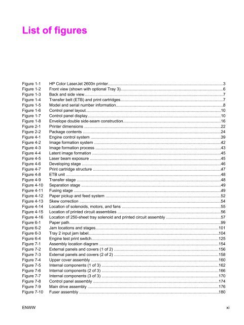
List of figures<br />
Figure 1-1 <strong>HP</strong> <strong>Color</strong> <strong>LaserJet</strong> <strong>2600n</strong> printer......................................................................................................3<br />
Figure 1-2 Front view (shown with optional Tray 3)...........................................................................................6<br />
Figure 1-3 Back and side view...........................................................................................................................7<br />
Figure 1-4 Transfer belt (ETB) and print cartridges...........................................................................................7<br />
Figure 1-5 Model and serial number information...............................................................................................8<br />
Figure 1-6 Control panel layout.......................................................................................................................10<br />
Figure 1-7 Control panel display......................................................................................................................10<br />
Figure 1-8 Envelope double side-seam construction......................................................................................16<br />
Figure 2-1 Printer dimensions .........................................................................................................................22<br />
Figure 2-2 Package contents ..........................................................................................................................24<br />
Figure 4-1 Engine control system ...................................................................................................................39<br />
Figure 4-2 Image formation system ................................................................................................................42<br />
Figure 4-3 Image formation process ...............................................................................................................43<br />
Figure 4-4 Latent image formation ..................................................................................................................45<br />
Figure 4-5 Laser beam exposure ....................................................................................................................45<br />
Figure 4-6 Developing stage ...........................................................................................................................46<br />
Figure 4-7 Print cartridge structure .................................................................................................................47<br />
Figure 4-8 ETB unit .........................................................................................................................................48<br />
Figure 4-9 Transfer stage ...............................................................................................................................48<br />
Figure 4-10 Separation stage ...........................................................................................................................49<br />
Figure 4-11 Fusing stage ..................................................................................................................................49<br />
Figure 4-12 Paper pickup and feed system ......................................................................................................52<br />
Figure 4-13 Skew correction .............................................................................................................................54<br />
Figure 4-14 Location of solenoids, motors, and fans .......................................................................................55<br />
Figure 4-15 Location of printed circuit assemblies ...........................................................................................56<br />
Figure 4-16 Location of 250-sheet tray solenoid and printed circuit assembly ................................................57<br />
Figure 6-1 Paper path......................................................................................................................................99<br />
Figure 6-2 Jam locations and stages.............................................................................................................101<br />
Figure 6-3 Tray 2 input jam label...................................................................................................................104<br />
Figure 6-4 Engine test print switch................................................................................................................125<br />
Figure 7-1 Assembly location diagram .........................................................................................................154<br />
Figure 7-2 External panels and covers (1 of 2) ............................................................................................156<br />
Figure 7-3 External panels and covers (2 of 2) ............................................................................................158<br />
Figure 7-4 Upper cover assembly .................................................................................................................160<br />
Figure 7-5 Internal components (1 of 3) .......................................................................................................162<br />
Figure 7-6 Internal components (2 of 3) .......................................................................................................166<br />
Figure 7-7 Internal components (3 of 3) .......................................................................................................170<br />
Figure 7-8 Control panel assembly ...............................................................................................................174<br />
Figure 7-9 Main drive assembly ....................................................................................................................176<br />
Figure 7-10 Fuser assembly ...........................................................................................................................180<br />
<strong>ENWW</strong> xi


