HP Color LaserJet 2600n Service Manual - ENWW - Market Point
HP Color LaserJet 2600n Service Manual - ENWW - Market Point
HP Color LaserJet 2600n Service Manual - ENWW - Market Point

Create successful ePaper yourself
Turn your PDF publications into a flip-book with our unique Google optimized e-Paper software.
<strong>HP</strong> <strong>Color</strong> <strong>LaserJet</strong> <strong>2600n</strong><br />
<strong>Service</strong> <strong>Manual</strong>
Copyright and License<br />
© 2005 Copyright Hewlett-Packard<br />
Development Company, L.P.<br />
Reproduction, adaptation, or translation<br />
without prior written permission is<br />
prohibited, except as allowed under the<br />
copyright laws.<br />
The information contained in this document<br />
is subject to change without notice.<br />
The only warranties for <strong>HP</strong> products and<br />
services are set forth in the express<br />
warranty statements accompanying such<br />
products and services. Nothing herein<br />
should be construed as constituting an<br />
additional warranty. <strong>HP</strong> shall not be liable<br />
for technical or editorial errors or omissions<br />
contained herein.<br />
Q6455-90930<br />
Edition 1, 2/2005<br />
FCC Class A Statement<br />
This equipment has been tested and found<br />
to comply with the limits for a Class A<br />
digital device, pursuant to Part 15 of the<br />
FCC Rules. These limits are designed to<br />
provide reasonable protection against<br />
harmful interference when the equipment is<br />
operated in a commercial environment.<br />
This equipment generates, uses and can<br />
radiate radio frequency energy and, if not<br />
installed and used in accordance with the<br />
instruction manual, may cause harmful<br />
interference to radio communications.<br />
Operation of this equipment in a residential<br />
area is likely to cause harmful interference,<br />
in which case the user will be required to<br />
correct the interference at his own<br />
expense. The end user of this product<br />
should be aware that any changes or<br />
modifications made to this equipment<br />
without the approval of Hewlett-Packard<br />
could result in the product not meeting the<br />
Class A limits, in which case the FCC<br />
could void the user’s authority to operate<br />
the equipment.<br />
Trademark Credits<br />
Adobe Photoshop® and PostScript are<br />
trademarks of Adobe Systems Incorporated.<br />
CorelDRAW is a trademark or registered<br />
trademark of Corel Corporation or Corel<br />
Corporation Limited.<br />
Microsoft®, Windows®, MS-DOS®, and<br />
Windows NT® are U.S. registered<br />
trademarks of Microsoft Corporation.<br />
Netscape and Netscape Navigator are<br />
U.S. trademarks of Netscape<br />
Communications Corporation.<br />
TrueType is a U.S. trademark of Apple<br />
Computer, Inc.<br />
ENERGY STAR® and the ENERGY STAR<br />
logo® are U.S. registered marks of the<br />
United States Environmental Protection<br />
Agency.
Table of contents<br />
1 Product information<br />
Quick access to printer information.........................................................................................................2<br />
Printer configuration................................................................................................................................3<br />
Printer features........................................................................................................................................4<br />
Walk around.............................................................................................................................................6<br />
Front view (shown with optional Tray 3).................................................................................6<br />
Back and side view.................................................................................................................7<br />
Control panel...........................................................................................................................8<br />
Understanding supplies status...............................................................................8<br />
Understanding printer status..................................................................................8<br />
Understanding control panel layout.......................................................................9<br />
Software.................................................................................................................................................11<br />
Supported drivers..................................................................................................................11<br />
Software and supported operating systems........................................................11<br />
Software for Windows...........................................................................................................11<br />
Software for Macintosh.........................................................................................................12<br />
Network software..................................................................................................................12<br />
Uninstalling software.............................................................................................................12<br />
Windows software................................................................................................12<br />
Macintosh software..............................................................................................13<br />
Print-media specifications......................................................................................................................14<br />
General guidelines................................................................................................................14<br />
Paper and print media...........................................................................................................14<br />
Printing and storage environment.........................................................................................14<br />
Envelopes.............................................................................................................................15<br />
Labels....................................................................................................................................17<br />
Transparencies.....................................................................................................................17<br />
Media support tables.............................................................................................................17<br />
Supported print media for Tray 1, Tray 2, and optional Tray 3............................17<br />
Unsupported media (media to avoid)...................................................................18<br />
2 Installation<br />
Site preparation ....................................................................................................................................22<br />
Operating environment ........................................................................................................22<br />
Minimum system requirements ............................................................................................23<br />
Requirements for PC systems ............................................................................23<br />
Requirements for Macintosh systems (non-PostScript) .....................................23<br />
Package contents .................................................................................................................................24<br />
Install input devices ..............................................................................................................................25<br />
<strong>ENWW</strong> iii
Installing optional Tray 3 ......................................................................................................25<br />
Loading Tray 1 .....................................................................................................................25<br />
Installing supplies .................................................................................................................27<br />
Print cartridges ....................................................................................................27<br />
3 Managing and maintenance<br />
Managing supplies ................................................................................................................................32<br />
Life expectancies of supplies ...............................................................................................32<br />
Checking and ordering supplies ..........................................................................................32<br />
To check status using the control panel .............................................................32<br />
To check and order supplies using <strong>HP</strong> Toolbox .................................................32<br />
Storing supplies ...................................................................................................................33<br />
Replacing and recycling supplies ........................................................................................33<br />
Replacing the print cartridges .............................................................................33<br />
<strong>HP</strong> policy on non-<strong>HP</strong> supplies .............................................................................................33<br />
<strong>HP</strong> anti-counterfeit website ..................................................................................................33<br />
Cleaning the printer ..............................................................................................................................34<br />
To clean the printer at the printer .........................................................................................34<br />
To clean the fuser using <strong>HP</strong> Toolbox ..................................................................................35<br />
Cleaning spilled toner ..........................................................................................................35<br />
Calibrating the printer ...........................................................................................................................36<br />
To calibrate the printer at the printer ...................................................................................36<br />
To calibrate the printer from the <strong>HP</strong> Toolbox .......................................................................36<br />
4 Operational theory<br />
Engine control system ..........................................................................................................................38<br />
Basic sequence of operation ...............................................................................................38<br />
Power-on sequence .............................................................................................................39<br />
Motors and fans ...................................................................................................................39<br />
Main motor failure detection ................................................................................40<br />
Fan motor failure detection .................................................................................40<br />
Image formation system .......................................................................................................................41<br />
Image formation process .....................................................................................................43<br />
Latent image formation .......................................................................................44<br />
Laser/scanner system .........................................................................................45<br />
Developing stage .................................................................................................................45<br />
Print cartridge ......................................................................................................46<br />
Transfer belt (ETB) ..............................................................................................47<br />
Transfer stage ......................................................................................................................48<br />
Separation stage ..................................................................................................................49<br />
Fusing stage ........................................................................................................................49<br />
Pickup and feed system .......................................................................................................................51<br />
<strong>Manual</strong> feed slot pickup mechanism ...................................................................................53<br />
Paper feed mechanism ........................................................................................................53<br />
Skew correction by the registration shutter .........................................................................53<br />
Jam detection .......................................................................................................................54<br />
Solenoid, motor, and fan locations ......................................................................................55<br />
Printed circuit assembly locations ........................................................................................55<br />
250-sheet tray solenoid and printed circuit locations ..........................................................56<br />
<strong>Service</strong>-only tools (SERVICE ONLY) ...................................................................................................58<br />
iv <strong>ENWW</strong>
General timing chart .............................................................................................................58<br />
Printer calibration .................................................................................................................59<br />
5 Removal and replacement<br />
Overview................................................................................................................................................62<br />
<strong>Service</strong> approach...................................................................................................................................63<br />
Pre-service procedures.........................................................................................................63<br />
Removal and replacement procedures.................................................................................................64<br />
Print cartridge replacement...................................................................................................64<br />
ETB removal and replacement.............................................................................................66<br />
Fuser removal and replacement...........................................................................................74<br />
Formatter removal and replacement....................................................................................82<br />
DC controller removal and replacement...............................................................................86<br />
Separation pad removal and replacement............................................................................88<br />
Paper pickup roller removal and replacement......................................................................89<br />
Control panel removal and replacement...............................................................................91<br />
6 Troubleshooting<br />
Troubleshooting process.......................................................................................................................98<br />
Troubleshooting checklist.....................................................................................................98<br />
Clearing jams ........................................................................................................................................99<br />
Paper path............................................................................................................................99<br />
Common causes of paper jams..........................................................................................100<br />
Where to look for jams........................................................................................................101<br />
Jams inside the printer........................................................................................................102<br />
Input jams...........................................................................................................................103<br />
Tray 1.................................................................................................................103<br />
Tray 2.................................................................................................................104<br />
Output jams.........................................................................................................................104<br />
Jams in the top bin.............................................................................................104<br />
Pickup delay jam................................................................................................105<br />
Pickup stationary jam.........................................................................................105<br />
Delivery delay jam..............................................................................................105<br />
Wrapping jam......................................................................................................................105<br />
Delivery stationary jam.......................................................................................................105<br />
Start-up residual paper jam................................................................................................105<br />
Door open jam....................................................................................................................106<br />
Print problems......................................................................................................................................107<br />
Getting information..............................................................................................................107<br />
Control panel messages....................................................................................107<br />
Alert and warning messages.............................................................107<br />
Critical error messages.....................................................................108<br />
Supplies messages...........................................................................109<br />
Status messages...............................................................................112<br />
Status log only messages.................................................................112<br />
Reports menu.....................................................................................................113<br />
Configuration page.............................................................................................114<br />
Supplies Status page.........................................................................................116<br />
Status log...........................................................................................................116<br />
<strong>Service</strong> menu settings........................................................................................118<br />
<strong>ENWW</strong> v
Secondary service menu....................................................................................118<br />
Printed image quality problems..........................................................................................119<br />
Improving print quality........................................................................................119<br />
Paper Types menu............................................................................119<br />
Print Modes menu.............................................................................120<br />
Print quality menu..............................................................................121<br />
Understanding print-quality settings...................................................................121<br />
To temporarily change print-quality settings.....................................122<br />
To change print-quality settings for all future jobs............................122<br />
Identifying and correcting printed image defects...............................................122<br />
Print-quality checklist.........................................................................122<br />
Paper handling issues........................................................................................................123<br />
Wrong size/type media.......................................................................................123<br />
Cannot select a tray or feature to use................................................................123<br />
Performance problems.......................................................................................................123<br />
Functional tests (SERVICE ONLY).....................................................................................................125<br />
Engine test print..................................................................................................................125<br />
<strong>Service</strong> mode functions (SERVICE ONLY).........................................................................................126<br />
Cold reset............................................................................................................................126<br />
NVRAM initializer................................................................................................................126<br />
Super NVRAM initializer.....................................................................................................126<br />
Restoring page counts and serial number..........................................................................127<br />
Cleaning the ETB................................................................................................................127<br />
Troubleshooting tools..........................................................................................................................128<br />
Printer pages and reports...................................................................................................128<br />
Demo page.........................................................................................................128<br />
Configuration page.............................................................................................129<br />
Event log............................................................................................................131<br />
Supplies Status page.........................................................................................131<br />
Fuser cleaning page...........................................................................................132<br />
Print quality troubleshooting pages....................................................................132<br />
Control panel messages (error codes)..............................................................132<br />
Alert and warning messages.............................................................132<br />
Critical error messages.....................................................................133<br />
Supplies messages...........................................................................134<br />
Status messages................................................................................................................137<br />
Status log only messages...................................................................................................137<br />
<strong>Service</strong> menu......................................................................................................................137<br />
Restoring the factory-set defaults......................................................................138<br />
To restore the factory-set defaults....................................................138<br />
General print quality issues................................................................................................138<br />
Solving issues with color documents..................................................................................142<br />
<strong>HP</strong> Toolbox..........................................................................................................................................144<br />
<strong>HP</strong> Toolbox.........................................................................................................................144<br />
To view <strong>HP</strong> Toolbox...........................................................................................144<br />
Troubleshooting tab...........................................................................................144<br />
Print quality troubleshooting pages....................................................................................144<br />
Printer calibration................................................................................................................144<br />
Cleaning page.....................................................................................................................144<br />
Configuration page..............................................................................................................145<br />
vi <strong>ENWW</strong>
Diagnostic resources...........................................................................................................................146<br />
Reports menu.....................................................................................................................146<br />
Network/Web diagnostics tools...........................................................................................146<br />
Repetitive image defect ruler...............................................................................................................147<br />
Firmware and software updates..........................................................................................................148<br />
7 Parts and diagrams<br />
Overview .............................................................................................................................................150<br />
Assembly locations .............................................................................................................................154<br />
Covers ................................................................................................................................................160<br />
Internal assemblies .............................................................................................................................162<br />
Input devices .......................................................................................................................................186<br />
Diagrams ............................................................................................................................................208<br />
Alphabetical parts list...........................................................................................................................209<br />
Numerical parts list..............................................................................................................................230<br />
Appendix A Product specifications<br />
Physical specifications ........................................................................................................................252<br />
Supplies specifications .......................................................................................................................253<br />
Print cartridge life ...............................................................................................................253<br />
Electrical specifications ......................................................................................................................254<br />
Environmental specifications ..............................................................................................................255<br />
Acoustical specifications .....................................................................................................................256<br />
Appendix B Product warranty statements<br />
Hewlett-Packard limited warranty statement ......................................................................................258<br />
Print Cartridge Limited Warranty Statement ......................................................................................259<br />
Appendix C Regulatory statements<br />
Declaration of Conformity ...................................................................................................................262<br />
Laser safety statement .......................................................................................................................263<br />
Canadian DOC statement ..................................................................................................................264<br />
VCCI statement (Japan) .....................................................................................................................265<br />
Korean EMI statement ........................................................................................................................266<br />
Finnish laser statement ......................................................................................................................267<br />
Index....................................................................................................................................................................269<br />
<strong>ENWW</strong> vii
viii <strong>ENWW</strong>
List of tables<br />
Table 1-1 Printer features.................................................................................................................................4<br />
Table 1-2 <strong>HP</strong> <strong>Color</strong> <strong>LaserJet</strong> <strong>2600n</strong> printer software.....................................................................................11<br />
Table 1-3 Envelope specifications..................................................................................................................15<br />
Table 1-4 Envelope size ranges.....................................................................................................................16<br />
Table 1-5 Tray 1 and Tray 2 specifications....................................................................................................17<br />
Table 1-6 Optional Tray 3 specifications........................................................................................................18<br />
Table 3-1 Print cartridge life ..........................................................................................................................32<br />
Table 4-1 Basic operational sequence ..........................................................................................................38<br />
Table 4-2 Motor specifications .......................................................................................................................40<br />
Table 5-1 User-replaceable parts...................................................................................................................62<br />
Table 6-1 Troubleshooting checklist...............................................................................................................98<br />
Table 6-2 Status log only messages............................................................................................................112<br />
Table 6-3 Configuration page.......................................................................................................................114<br />
Table 6-4 Supplies Status page...................................................................................................................116<br />
Table 6-5 Status log messages....................................................................................................................117<br />
Table 6-6 Print modes for paper types.........................................................................................................120<br />
Table 6-7 Extended print modes..................................................................................................................120<br />
Table 6-8 Optimize menu.............................................................................................................................121<br />
Table 6-9 Performance issues......................................................................................................................123<br />
Table 6-10 Configuration page.......................................................................................................................129<br />
Table 6-11 Supplies Status page...................................................................................................................131<br />
Table 6-12 Status log only messages............................................................................................................137<br />
Table 6-13 General print quality issues..........................................................................................................138<br />
Table 6-14 <strong>Color</strong> document issues.................................................................................................................142<br />
Table 6-15 Repetitive image defects..............................................................................................................147<br />
Table 7-1 Available replaceable parts .........................................................................................................150<br />
Table 7-2 Technical support Web sites .......................................................................................................152<br />
Table 7-3 Accessories .................................................................................................................................152<br />
Table 7-4 Assembly locations ......................................................................................................................155<br />
Table 7-5 External panels and covers (1 of 2) ............................................................................................157<br />
Table 7-6 External panels and covers (2 of 2) ............................................................................................159<br />
Table 7-7 Upper assembly cover .................................................................................................................161<br />
Table 7-8 Internal components (1 of 3) .......................................................................................................163<br />
Table 7-9 Internal components (2 of 3) .......................................................................................................167<br />
Table 7-10 Internal components (3 of 3) .......................................................................................................171<br />
Table 7-11 Control panel assembly ...............................................................................................................175<br />
Table 7-12 Main drive assembly ....................................................................................................................177<br />
Table 7-13 Fuser assembly ...........................................................................................................................181<br />
Table 7-14 PCB assembly location Tray 2 ....................................................................................................185<br />
Table 7-15 Tray 2 input tray (cassette) .........................................................................................................187<br />
<strong>ENWW</strong> ix
Table 7-16 250-sheet input tray (cassette) ....................................................................................................191<br />
Table 7-17 Tray 2 sheet input tray internal components ...............................................................................193<br />
Table 7-18 Paper pick-up feeder assembly for Tray 2 ..................................................................................197<br />
Table 7-19 Tray 3 input tray (cassette) .........................................................................................................201<br />
Table 7-20 Paper pickup feeder assembly (Tray 3) ......................................................................................205<br />
Table 7-21 Paper pickup feeder assembly (Tray 3) ......................................................................................207<br />
Table 7-22 Alphabetical parts list...................................................................................................................209<br />
Table 7-23 Numerical parts list.......................................................................................................................230<br />
Table A-1 Printer specifications ...................................................................................................................252<br />
Table A-2 Supplies specifications ................................................................................................................253<br />
Table A-3 Print cartridge specifications .......................................................................................................253<br />
Table A-4 Electrical specifications ...............................................................................................................254<br />
Table A-5 Environmental specifications .......................................................................................................255<br />
Table A-6 Acoustical specifications .............................................................................................................256<br />
x <strong>ENWW</strong>
List of figures<br />
Figure 1-1 <strong>HP</strong> <strong>Color</strong> <strong>LaserJet</strong> <strong>2600n</strong> printer......................................................................................................3<br />
Figure 1-2 Front view (shown with optional Tray 3)...........................................................................................6<br />
Figure 1-3 Back and side view...........................................................................................................................7<br />
Figure 1-4 Transfer belt (ETB) and print cartridges...........................................................................................7<br />
Figure 1-5 Model and serial number information...............................................................................................8<br />
Figure 1-6 Control panel layout.......................................................................................................................10<br />
Figure 1-7 Control panel display......................................................................................................................10<br />
Figure 1-8 Envelope double side-seam construction......................................................................................16<br />
Figure 2-1 Printer dimensions .........................................................................................................................22<br />
Figure 2-2 Package contents ..........................................................................................................................24<br />
Figure 4-1 Engine control system ...................................................................................................................39<br />
Figure 4-2 Image formation system ................................................................................................................42<br />
Figure 4-3 Image formation process ...............................................................................................................43<br />
Figure 4-4 Latent image formation ..................................................................................................................45<br />
Figure 4-5 Laser beam exposure ....................................................................................................................45<br />
Figure 4-6 Developing stage ...........................................................................................................................46<br />
Figure 4-7 Print cartridge structure .................................................................................................................47<br />
Figure 4-8 ETB unit .........................................................................................................................................48<br />
Figure 4-9 Transfer stage ...............................................................................................................................48<br />
Figure 4-10 Separation stage ...........................................................................................................................49<br />
Figure 4-11 Fusing stage ..................................................................................................................................49<br />
Figure 4-12 Paper pickup and feed system ......................................................................................................52<br />
Figure 4-13 Skew correction .............................................................................................................................54<br />
Figure 4-14 Location of solenoids, motors, and fans .......................................................................................55<br />
Figure 4-15 Location of printed circuit assemblies ...........................................................................................56<br />
Figure 4-16 Location of 250-sheet tray solenoid and printed circuit assembly ................................................57<br />
Figure 6-1 Paper path......................................................................................................................................99<br />
Figure 6-2 Jam locations and stages.............................................................................................................101<br />
Figure 6-3 Tray 2 input jam label...................................................................................................................104<br />
Figure 6-4 Engine test print switch................................................................................................................125<br />
Figure 7-1 Assembly location diagram .........................................................................................................154<br />
Figure 7-2 External panels and covers (1 of 2) ............................................................................................156<br />
Figure 7-3 External panels and covers (2 of 2) ............................................................................................158<br />
Figure 7-4 Upper cover assembly .................................................................................................................160<br />
Figure 7-5 Internal components (1 of 3) .......................................................................................................162<br />
Figure 7-6 Internal components (2 of 3) .......................................................................................................166<br />
Figure 7-7 Internal components (3 of 3) .......................................................................................................170<br />
Figure 7-8 Control panel assembly ...............................................................................................................174<br />
Figure 7-9 Main drive assembly ....................................................................................................................176<br />
Figure 7-10 Fuser assembly ...........................................................................................................................180<br />
<strong>ENWW</strong> xi
Figure 7-11 PCB assembly location (Tray 2) ..................................................................................................184<br />
Figure 7-12 Tray 2 input tray (cassette) .........................................................................................................186<br />
Figure 7-13 250-sheet input tray (cassette) ....................................................................................................190<br />
Figure 7-14 Tray 2 input tray internal components .........................................................................................192<br />
Figure 7-15 Paper pick-up feeder assembly for Tray 2 ..................................................................................196<br />
Figure 7-16 Tray 3 input tray (cassette) .........................................................................................................200<br />
Figure 7-17 Paper pickup feeder assembly (Tray 3) ......................................................................................204<br />
Figure 7-18 PCB assembly location optional Tray 3 ......................................................................................206<br />
Figure 7-19 General circuit diagram ...............................................................................................................208<br />
Figure C-1 VCCI statement ...........................................................................................................................265<br />
Figure C-2 Korean EMI statement .................................................................................................................266<br />
xii <strong>ENWW</strong>
1 Product information<br />
This section provides information about the following topics:<br />
● Quick access to printer information<br />
● Printer configuration<br />
● Printer features<br />
● Walk around<br />
● Software<br />
● Print-media specifications<br />
<strong>ENWW</strong> 1
Quick access to printer information<br />
User guide<br />
Contains detailed information for using the printer and troubleshooting problems. This guide is<br />
available in two formats on the CD-ROM that came with the printer: in PDF format for printing and<br />
HTML format for online viewing. It is also available through the <strong>HP</strong> Toolbox software.<br />
Getting started guide<br />
Provides step-by-step instructions for installing and setting up the printer.<br />
<strong>HP</strong> Toolbox<br />
Use to check the printer status and settings and to view troubleshooting information and online<br />
documentation.<br />
Embedded Web server<br />
Use to view and configure printer settings and networking information.<br />
2 Chapter 1 Product information <strong>ENWW</strong>
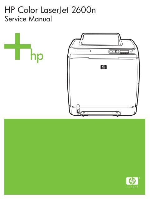
Printer configuration<br />
<strong>HP</strong> <strong>Color</strong> <strong>LaserJet</strong> <strong>2600n</strong><br />
The <strong>HP</strong> <strong>Color</strong> <strong>LaserJet</strong> <strong>2600n</strong> printer is available in the configuration described below.<br />
Figure 1-1 <strong>HP</strong> <strong>Color</strong> <strong>LaserJet</strong> <strong>2600n</strong> printer<br />
The <strong>HP</strong> <strong>Color</strong> <strong>LaserJet</strong> <strong>2600n</strong> printer is a four-color laser printer that prints eight pages per minute<br />
(ppm) in both monochrome (black and white) and color.<br />
■ Trays. The printer comes with a single sheet priority feed slot (Tray 1) and a universal tray<br />
(Tray 2) that holds up to 250 sheets of various paper types and sizes or 10 envelopes. It<br />
supports an optional 250-sheet paper tray (optional Tray 3).<br />
■ Connectivity. The printer provides a Hi-Speed Universal Serial Bus (USB) 2.0 port for<br />
connectivity and an <strong>HP</strong> built-in internal print server for connecting to a 10/100Base-T network.<br />
■ Memory. The printer contains 16 megabytes (MB) of synchronous dynamic random access<br />
memory (SDRAM). No additional memory can be added.<br />
<strong>ENWW</strong> Printer configuration 3
Printer features<br />
Table 1-1 Printer features<br />
Feature <strong>HP</strong> <strong>Color</strong> <strong>LaserJet</strong> <strong>2600n</strong> printer<br />
<strong>Color</strong> printing ■ Provides laser printing in full color by using the four<br />
process colors: cyan, magenta, yellow, and black<br />
(CMYK).<br />
Fast print speed ■ Prints in black on letter-size paper up to 8 ppm and on<br />
A4-size paper up to 8 ppm. Prints in color on A4/letter at<br />
8 ppm.<br />
Excellent print quality ■ ImageREt 2400 provides 2400 dpi equivalent color<br />
quality through a multilevel printing process.<br />
■ True 600 by 600 dots per inch (dpi) text and graphics.<br />
■ Adjustable settings to optimize print quality.<br />
■ The <strong>HP</strong> UltraPrecise print cartridge has a finer toner<br />
formulation that provides sharper text and graphics.<br />
Ease of use ■ Few supplies to order. Supplies are easy to install.<br />
■ Convenient access to printer information and settings by<br />
using the <strong>HP</strong> Toolbox software.<br />
■ Convenient access to all supplies and to the paper path<br />
through the front door.<br />
Flexible paper handling ■ Trays 1 and 2 for letterhead, envelopes, labels,<br />
transparencies, custom-sized media, postcards,<br />
<strong>HP</strong> <strong>LaserJet</strong> glossy paper, <strong>HP</strong> <strong>LaserJet</strong> Tough paper,<br />
heavy paper, and <strong>HP</strong> Laser Photo paper.<br />
■ A 125-sheet top output bin.<br />
■ Print on Both Sides (manually).<br />
Interface connections ■ Hi-Speed USB 2.0 port.<br />
■ The <strong>HP</strong> <strong>Color</strong> <strong>LaserJet</strong> <strong>2600n</strong> printer includes an<br />
<strong>HP</strong> built-in internal print server for connecting to a<br />
10/100Base-T network.<br />
Energy savings ■ The printer automatically conserves electricity by<br />
substantially reducing power consumption when it is not<br />
printing.<br />
■ As an ENERGY STAR® partner, Hewlett-Packard<br />
Company has determined that this product meets<br />
ENERGY STAR® guidelines for energy efficiency.<br />
ENERGY STAR® is a U.S. registered service mark of<br />
the United States Environmental Protection Agency.<br />
Economical printing ■ N-up printing (printing more than one page on a sheet)<br />
and Printing on Both Sides features save paper.<br />
4 Chapter 1 Product information <strong>ENWW</strong>
Table 1-1 Printer features (continued)<br />
Feature <strong>HP</strong> <strong>Color</strong> <strong>LaserJet</strong> <strong>2600n</strong> printer<br />
Supplies ■ A Supplies Status page with print cartridge gauges that<br />
show the supply levels that remain. For <strong>HP</strong> supplies only.<br />
■ No-shake cartridge design.<br />
■ Authentication for <strong>HP</strong> print cartridges.<br />
■ Internet-enabled, supplies-ordering capability.<br />
Accessibility ■ Online user guide that is compatible with text<br />
screen-readers.<br />
■ All doors and covers can be opened by using one hand.<br />
Expandability ■ Optional Tray 3. This 250-sheet universal tray reduces<br />
how often you have to add paper to the printer. Only<br />
one additional 250-sheet tray can be installed on the<br />
printer.<br />
Memory ■ 16 MB of DRAM.<br />
NOTE No additional memory can be added.<br />
<strong>ENWW</strong> Printer features 5
Walk around<br />
The following illustrations identify the locations and names of key components of this printer.<br />
Front view (shown with optional Tray 3)<br />
Figure 1-2 Front view (shown with optional Tray 3)<br />
1 Output bin<br />
2 Printer control panel<br />
3 Front door<br />
4 Tray 2 (250 sheets)<br />
5 Tray 1 (single sheet priority feed slot)<br />
6 Tray 3 (optional; 250 sheets)<br />
6 Chapter 1 Product information <strong>ENWW</strong>
Back and side view<br />
Figure 1-3 Back and side view<br />
1 On/off switch<br />
2 Power connection<br />
3 Engine test button access door<br />
4 Access door<br />
5 Dust cover<br />
6 <strong>HP</strong> built-in internal print server for connecting to a 10/100Base-T network<br />
7 USB connection<br />
Figure 1-4 Transfer belt (ETB) and print cartridges<br />
1 Transfer belt (ETB)<br />
2 Print cartridges<br />
CAUTION Do not place anything on the transfer belt , which is located on the inside of the<br />
front door. Otherwise, the printer may be damaged, adversely affecting print quality.<br />
<strong>ENWW</strong> Walk around 7
Model and serial number location<br />
The model number and serial numbers are listed on identification labels located on the rear of the<br />
printer. The model number is alphanumeric, such as Q6455A, for the <strong>HP</strong> <strong>Color</strong> <strong>LaserJet</strong> <strong>2600n</strong><br />
printer. The serial number contains information about the country/region of origin, the printer version,<br />
production code, and the production number of the printer.<br />
Figure 1-5 Model and serial number information<br />
Control panel<br />
Understanding supplies status<br />
The supplies gauges show the consumption levels of print cartridges (black, yellow, cyan, and<br />
magenta).<br />
Black, yellow, cyan, and magenta supplies status gauges<br />
A ? appears instead of the consumption level when the level is not known. This can occur in the<br />
following circumstances:<br />
■ Missing cartridges<br />
■ Incorrectly placed cartridges<br />
■ Cartridges with an error<br />
■ Some non-<strong>HP</strong> cartridges<br />
The supplies gauge appears whenever the printer shows the Ready state with no warnings. It will<br />
also appear when the printer shows a warning or error message concerning a print cartridge or<br />
multiple supplies. If a supply is empty, the gauge will flash.<br />
Understanding printer status<br />
Cancel Job button<br />
■ When the Ready light is blinking, pressing (CANCEL JOB) cancels the current job.<br />
■ When a supplies status gauge is blinking and the Attention light is on (indicating that a non-<strong>HP</strong><br />
supply has been installed), pressing (SELECT) allows you to continue printing.<br />
8 Chapter 1 Product information <strong>ENWW</strong>
CAUTION You might not receive any indication when a non-<strong>HP</strong> supply is empty. For more<br />
information about using non-<strong>HP</strong> print cartridges, see <strong>HP</strong> policy on non-<strong>HP</strong> supplies. If you<br />
continue printing after the supply is empty, damage to the printer can occur. See Hewlett-<br />
Packard limited warranty statement.<br />
Attention light<br />
Generally, the Attention light blinks when the printer is out of paper, when a jam has occurred, or<br />
when other problems that need attention occur.<br />
The Attention light is on and one of the Supplies Status gauges is blinking the first time a non-<strong>HP</strong><br />
supply is installed.<br />
Ready light<br />
The Ready light is on when the printer is ready to print (experiencing no errors that prevent printing)<br />
and blinks when it is receiving data to be printed.<br />
Ready light and Select button<br />
■ When the Ready light is on and the Attention light is blinking, pressing (SELECT) continues the<br />
print job after you load print media for a manual feed, or clears some errors.<br />
■ When the Ready light is blinking, the front door has been opened and then closed. Press<br />
(SELECT) to return the printer to the Ready state. If you do not press (SELECT), the printer<br />
returns to the Ready state on its own.<br />
Left and Right arrow buttons<br />
Use the (LEFT ARROW) and (RIGHT ARROW) buttons to navigate through the printer control panel<br />
menus.<br />
A Demo page can be printed by pressing the (LEFT ARROW) and (RIGHT ARROW) buttons<br />
simultaneously.<br />
Understanding control panel layout<br />
This section provides information about printer status and control panel layout.<br />
Control panel layout<br />
The printer contains the following lights and buttons on the control panel:<br />
<strong>ENWW</strong> Walk around 9
Figure 1-6 Control panel layout<br />
1 <strong>Color</strong> print cartridge indicators<br />
2 Attention light (amber)<br />
3 Ready light (green)<br />
4<br />
CANCEL JOB button<br />
5 Message area<br />
6<br />
7<br />
8<br />
Display<br />
RIGHT ARROW button<br />
SELECT button<br />
LEFT ARROW button<br />
Figure 1-7 Control panel display<br />
1<br />
The printer display gives you information about the printer, job status, and levels of supplies.<br />
1 Message area<br />
2 Supplies gauges<br />
3 Print cartridge colors are indicated from left to right: black, yellow, cyan, and magenta<br />
10 Chapter 1 Product information <strong>ENWW</strong>
Software<br />
This section contains information about the software used with the <strong>HP</strong> <strong>Color</strong> <strong>LaserJet</strong> <strong>2600n</strong> printer.<br />
Supported drivers<br />
Software and supported operating systems<br />
For easy printer setup and access to the full range of printer features, <strong>HP</strong> strongly recommends that<br />
you install the software that is provided. Not all software is available in all languages. See the Getting<br />
Started Guide for installation instructions, and see the Readme file for the latest software information.<br />
The most recent drivers, additional drivers, and other software are available from the Internet and<br />
other sources.<br />
The printer supports the following operating systems:<br />
■ Microsoft® Windows® 98 Second Edition and Windows Millennium Edition (Me) (Add Printer<br />
installation)<br />
■ Microsoft® Windows® 2000 and Windows XP<br />
■ Microsoft® Windows® Server 2003<br />
■ Macintosh OS X v10.2 and later<br />
The following table lists the software that is available for your operating system.<br />
Table 1-2 <strong>HP</strong> <strong>Color</strong> <strong>LaserJet</strong> <strong>2600n</strong> printer software<br />
Feature Windows 98 Second<br />
Edition, Me<br />
Windows Installer<br />
Windows printer driver<br />
<strong>HP</strong> Toolbox software<br />
Macintosh Installer<br />
Macintosh printer drivers<br />
Software for Windows<br />
Windows 2000 and XP Macintosh OS X v10.2 and<br />
later<br />
When you install the software for Windows, you can directly connect the printer to a computer by<br />
using a USB cable or you can connect the printer to the network by using <strong>HP</strong> built-in networking. See<br />
the Getting Started Guide for installation instructions, and see the Readme file for the latest software<br />
information.<br />
The following software is available to all users of the printer, whether you connected the printer<br />
directly to a computer by using a USB cable, or to the network through the <strong>HP</strong> built-in networking<br />
internal print server.<br />
<strong>ENWW</strong> Software 11
Printer drivers<br />
A printer driver is a software component that provides access to printer features and provides the<br />
means for the computer to communicate with the printer.<br />
Using Help<br />
The printer driver has Help dialog boxes that can be activated from the Help button in the printer<br />
driver, the F1 key on the computer keyboard, or the question mark symbol (?) in the upper-right<br />
corner of the printer driver. These Help dialog boxes give detailed information about the specific<br />
printer driver. Help for the printer driver is separate from the Help for your program.<br />
<strong>HP</strong> Toolbox<br />
You must perform a complete software installation to use the <strong>HP</strong> Toolbox.<br />
The <strong>HP</strong> Toolbox provides links to printer status information and help information, such as the user<br />
guide; and tools for diagnosing and solving problems. You can also view explanations and<br />
animations on the control panel. See Managing and maintenance for more information.<br />
Software for Macintosh<br />
The printer includes the following software for Macintosh computers.<br />
Macintosh printer driver<br />
When you install the software for Macintosh, you can directly connect the printer to a computer by<br />
using a USB cable or you can connect the printer to the network by using <strong>HP</strong> built-in networking. If<br />
you are connected via the network, you can configure your printer using the embedded Web server.<br />
Network software<br />
Supported networks<br />
The <strong>HP</strong> <strong>Color</strong> <strong>LaserJet</strong> <strong>2600n</strong> printer supports network printing on Windows and Mac systems.<br />
Supported utilities/applications/tools<br />
■ <strong>HP</strong> <strong>Color</strong> <strong>LaserJet</strong> <strong>2600n</strong> <strong>HP</strong> Toolbox<br />
For IP configuration, in <strong>HP</strong> Toolbox, select Device Settings, and then select the Networking<br />
tab. For more information about the <strong>HP</strong> Toolbox, see <strong>HP</strong> Toolbox.<br />
■ Embedded Web server (EWS)<br />
If the printer is connected to a network, access the EWS by typing the printer IP address into the<br />
address field of a Web browser, and then selecting the Networking tab.<br />
Uninstalling software<br />
Uninstall software by using the following directions for your operating system.<br />
Windows software<br />
After a printing system installation, use the uninstall icon in the <strong>HP</strong> <strong>Color</strong> <strong>LaserJet</strong> <strong>2600n</strong> printer<br />
program group to select and remove any or all of the <strong>HP</strong> printing system components.<br />
12 Chapter 1 Product information <strong>ENWW</strong>
Starting the Uninstaller<br />
1 Click Start, select Programs (All Programs for Windows XP) and choose <strong>HP</strong>.<br />
2 In the <strong>HP</strong> <strong>Color</strong> <strong>LaserJet</strong> <strong>2600n</strong> program group, click the <strong>HP</strong> <strong>Color</strong> <strong>LaserJet</strong> <strong>2600n</strong> uninstall<br />
icon.<br />
3 The uninstaller guides you through removing the printing system components.<br />
NOTE For driver-only (Add Printer/New Driver) installations, delete the printer icon from the<br />
Printers folder (Windows 98 Second Edition, Windows Me, Windows 2000, and Windows XP).<br />
Macintosh software<br />
To remove the printer from your Macintosh use the following steps:<br />
1 Open Print Center (v10.2) or Print Setup Utility (v10.3).<br />
2 Select the printer name.<br />
3 Select Delete.<br />
<strong>ENWW</strong> Software 13
Print-media specifications<br />
This section contains information about specifications for the quality of print media, guidelines for<br />
print media usage, and guidelines for print media storage.<br />
General guidelines<br />
Some print media might meet all of the guidelines in this manual and still not produce satisfactory<br />
results. This problem might be the result of improper handling, unacceptable temperature and<br />
humidity levels, or other variables over which Hewlett-Packard has no control.<br />
Before purchasing large quantities of print media, always test a sample and make sure that the print<br />
media meets the requirements specified in the <strong>HP</strong> <strong>LaserJet</strong> Printer Family Print Media Guide<br />
available at http://www.hp.com/support/ljpaperguide.<br />
CAUTION Using print media that does not meet <strong>HP</strong> specifications can cause problems for<br />
the printer, requiring repair. This repair is not covered by the Hewlett-Packard warranty or<br />
service agreements.<br />
CAUTION Use only paper designed for laser printers. Paper for inkjet printers may damage<br />
the printer.<br />
This printer accepts a variety of media, such as cut-sheet paper (including up to 100% recycled-fibercontent<br />
paper), envelopes, labels, transparencies, <strong>HP</strong> <strong>LaserJet</strong> glossy paper, <strong>HP</strong> <strong>LaserJet</strong> Tough<br />
paper, <strong>HP</strong> <strong>LaserJet</strong> Photo paper, and custom-size paper. Properties such as weight, composition,<br />
grain, and moisture content are important factors that affect printer performance and output quality.<br />
Print media that does not meet the guidelines outlined in this manual can cause the following<br />
problems:<br />
■ Poor print quality<br />
■ Increased jams<br />
■ Premature wear on the printer, requiring repair<br />
Paper and print media<br />
For print-media specifications, see Media support tables.<br />
Printing and storage environment<br />
Ideally, the printing and media-storage environment should be at or near room temperature, and not<br />
too dry or too humid. Remember that paper is hygroscopic; it absorbs and loses moisture rapidly.<br />
Heat works with humidity to damage paper. Heat causes the moisture in paper to evaporate, while<br />
cold causes it to condense on the sheets. Heating systems and air conditioners remove most of the<br />
humidity from a room. As paper is opened and used, it loses moisture, causing streaks and<br />
smudging. Humid weather or water coolers can cause the humidity to increase in a room. As paper is<br />
opened and used it absorbs any excess moisture, causing light print and dropouts. Also, as paper<br />
loses and gains moisture it can distort. This issue can cause jams.<br />
As a result, paper storage and handling are as important as the paper-making process itself. Paper<br />
storage environmental conditions directly affect the feed operation and print quality.<br />
14 Chapter 1 Product information <strong>ENWW</strong>
Care should be taken not to purchase more paper than can be easily used in a short time (about<br />
three months). Paper stored for long periods can experience heat and moisture extremes, which can<br />
cause damage. Planning is important to prevent damage to a large supply of paper.<br />
Unopened paper in sealed reams can remain stable for several months before use. Opened<br />
packages of paper have more potential for environmental damage, especially if they are not wrapped<br />
with a moisture-proof barrier.<br />
The media-storage environment should be properly maintained to ensure optimum printer<br />
performance. The required condition is 20° to 24°C (68° to 75°F), with a relative humidity of 45% to<br />
55%. The following guidelines should be helpful when evaluating the paper's storage environment:<br />
■ Print media should be stored at or near room temperature.<br />
■ The air should not be too dry or too humid (to moderate the hygroscopic properties of paper).<br />
■ The best way to store an opened ream of paper is to rewrap it tightly in its moisture-proof<br />
wrapping. If the printer environment is subject to extremes, unwrap only the amount of paper to<br />
be used during the day's operation to prevent unwanted moisture changes.<br />
■ Avoid storing paper and print media near heating and air conditioning vents or near windows and<br />
doors that are frequently open.<br />
Envelopes<br />
Envelopes can be printed from Tray 1 or Tray 2. Select the type of envelope that you are using from<br />
the Print dialog box or the printer driver.<br />
In your program, set the margins for the envelope. The following table gives typical address margins<br />
for a commercial #10 or DL envelope.<br />
Table 1-3 Envelope specifications<br />
Type of address Top margin Left margin<br />
Return address 15 mm (0.6 inch) 15 mm (0.6 inch)<br />
Delivery address 51 mm (2 inches) 89 mm (3.5 inches)<br />
■ For the best print quality, position margins no closer than 15 mm (0.6 inch) from the edges of the<br />
envelope.<br />
■ Avoid printing over the area where the envelope seams meet.<br />
Envelope storage<br />
Proper storage of envelopes helps contribute to print quality. Envelopes should be stored flat. If air is<br />
trapped in an envelope and creates an air bubble, then the envelope might wrinkle during printing.<br />
Envelope construction<br />
Envelope construction is critical. Envelope fold lines can vary considerably, not only between<br />
manufacturers, but also within a box from the same manufacturer. Successful printing on envelopes<br />
<strong>ENWW</strong> Print-media specifications 15
depends upon the quality of the envelopes. When selecting envelopes, consider the following<br />
components:<br />
■ Weight: The weight of the envelope paper should not exceed 90 g/m 2 (24 lb) or jamming might<br />
occur.<br />
■ Construction: Before printing, envelopes should lie flat with less than 6 mm (0.25 inch) curl, and<br />
should not contain air.<br />
■ Condition: Envelopes should not be wrinkled, nicked, or otherwise damaged.<br />
■ Temperature: Use envelopes that are compatible with the heat and pressure of the printer. This<br />
printer fusing temperature is 210°C (410°F).<br />
■ Size: Use only envelopes that are within the following size ranges.<br />
Table 1-4 Envelope size ranges<br />
Tray Minimum Maximum<br />
Tray 1 or Tray 2 76 x 127 mm (3 x 5 inches) 216 x 356 mm (8.5 x 14 inches)<br />
Envelopes with double side-seams<br />
Double side-seam construction has vertical seams at both ends of the envelope rather than diagonal<br />
seams. This style might be more likely to wrinkle. Be sure the seam extends all the way to the corner<br />
of the envelope as illustrated below.<br />
1<br />
2<br />
Figure 1-8 Envelope double side-seam construction<br />
1 Acceptable<br />
2 Unacceptable<br />
Envelopes with adhesive strips or flaps<br />
Envelopes with a peel-off adhesive strip or with more than one flap that folds over to seal must use<br />
adhesives that are compatible with the heat and pressure in the printer. The extra flaps and strips<br />
might cause wrinkling, creasing, or even jams and might damage the fuser.<br />
16 Chapter 1 Product information <strong>ENWW</strong>
Labels<br />
Select the type of label that you are using from the Print dialog box or the printer driver.<br />
CAUTION To avoid damaging the printer, use only labels that are recommended for laser<br />
printers. To prevent serious jams, always use Tray 1 or Tray 2 to print on labels. Never print<br />
on the same sheet of labels more than once or print on a partial sheet of labels.<br />
When selecting labels, consider the quality of each component:<br />
■ Adhesives: The adhesive material should be stable at 210°C (410°F), which is the printer fusing<br />
temperature.<br />
■ Arrangement: Only use labels with no exposed backing between them. Labels can peel off<br />
sheets with spaces between the labels, causing serious jams.<br />
■ Curl: Before printing, labels must lie flat with no more than 13 mm (0.5 inch) of curl in any<br />
direction.<br />
■ Condition: Do not use labels that have wrinkles, bubbles, or other indications of separation.<br />
Transparencies<br />
Use only Tray 1 or Tray 2 to print on transparencies. Select Transparencies from the Print dialog<br />
box or the printer driver.<br />
The printer supports printing on color transparencies. Use only transparencies that are<br />
recommended for use in laser printers.<br />
Transparencies that are used in the printer must be able to withstand 210°C (410°F), which is the<br />
printer fusing temperature.<br />
CAUTION To avoid damage to the printer, use only transparencies that are recommended<br />
for use in laser printers.<br />
Media support tables<br />
This section contains information about the sizes, weights, and capacities of paper and other print<br />
media that each tray supports.<br />
Supported print media for Tray 1, Tray 2, and optional Tray 3<br />
This section contains information about the sizes, weights, and capacities of paper and other print<br />
media that each tray supports.<br />
Tray 1 and Tray 2 specifications<br />
Table 1-5 Tray 1 and Tray 2 specifications<br />
Tray 1 and Tray 2 Dimensions 1 Weight Capacity 2<br />
Paper Minimum: 76 x 127 mm<br />
(3 x 5 inches)<br />
60 to 163 g/m 2 (16 to 43 lb) Single sheet of 75 g/m 2<br />
(20 lb) paper for Tray 1<br />
<strong>ENWW</strong> Print-media specifications 17
Table 1-5 Tray 1 and Tray 2 specifications (continued)<br />
Tray 1 and Tray 2 Dimensions 1 Weight Capacity 2<br />
<strong>HP</strong> <strong>LaserJet</strong> glossy paper<br />
and <strong>HP</strong> <strong>LaserJet</strong> photo paper<br />
Maximum: 216 x 356 mm<br />
(8.5 x 14 inches)<br />
Same as the preceding<br />
listed minimum and<br />
maximum sizes.<br />
Up to 250 sheets for Tray 2<br />
75 to 163 g/m 2 (20 to 43 lb) Single sheet of <strong>HP</strong> <strong>LaserJet</strong><br />
glossy paper or <strong>HP</strong> <strong>LaserJet</strong><br />
photo paper for Tray 1<br />
Up to 25 mm (0.99 inch)<br />
stack height for Tray 2<br />
<strong>HP</strong> Premium Cover paper 3 200 g/m 2 (75 lb) cover Single sheet of <strong>HP</strong> Cover<br />
paper for Tray 1<br />
Transparencies and opaque<br />
film<br />
Thickness: 0.10 to 0.13 mm<br />
(3.9 to 5.1 mils)<br />
Labels Thickness: up to 0.23 mm<br />
(up to 9 mils)<br />
Up to 25 mm (0.99 inch)<br />
stack height for Tray 2<br />
Single sheet of transparency<br />
or opaque film for Tray 1<br />
Up to 50 sheets for Tray 2<br />
Single sheet of labels for<br />
Tray 1<br />
Up to 25 mm (0.99 inch)<br />
stack height for Tray 2<br />
Envelopes Up to 90 g/m 2 (16 to 24 lb) Single envelope for Tray 1<br />
Up to ten envelopes for<br />
Tray 2<br />
1 The printer supports a wide range of standard and custom sizes of print media. Check the printer driver for supported sizes.<br />
2 Capacity can vary depending on media weight and thickness, and environmental conditions.<br />
3 Hewlett-Packard does not guarantee results when printing with other types of heavy paper.<br />
Optional Tray 3 specifications<br />
Table 1-6 Optional Tray 3 specifications<br />
Optional Tray 3 (250–sheet<br />
tray)<br />
Paper Minimum: 76 x 127 mm<br />
(3 x 5 inches)<br />
Dimensions 1 Weight Capacity 2<br />
Maximum: 216 x 356 mm<br />
(8.5 x 14 inches)<br />
60 to 163 g/m 2 (16 to 43 lb) Up to 250 sheets<br />
1 The printer supports a wide range of standard and custom sizes of print media. Check the printer driver for supported sizes.<br />
2 Capacity can vary depending on media weight and thickness, and environmental conditions.<br />
Unsupported media (media to avoid)<br />
Avoid using the following media:<br />
■ Paper that has been stapled. Staples left in reused paper will cause printer damage that will<br />
require repairs that may not be covered under the warranty.<br />
■ Sheets of labels that have been used more than once or partial sheets of labels<br />
18 Chapter 1 Product information <strong>ENWW</strong>
■ Labels that are not specifically recommended for laser printers<br />
■ Labels that are separating from the backing sheet or are wrinkled or damaged in any way<br />
■ Transparencies that are not specifically recommended for laser printers<br />
■ Media that has been stored in a high-humidity environment<br />
■ Labels with exposed glue or adhesive<br />
<strong>ENWW</strong> Print-media specifications 19
20 Chapter 1 Product information <strong>ENWW</strong>
2 Installation<br />
This chapter contains information about the following topics.<br />
● Site preparation<br />
● Package contents<br />
● Install input devices<br />
<strong>ENWW</strong> 21
Site preparation<br />
Below are recommendations for the printer location and placement.<br />
Operating environment<br />
The printer must be kept in a proper location to maintain the performance level that has been set at<br />
the factory. In particular, be sure that the environment adheres to the specifications listed in this<br />
chapter.<br />
The printer must have 2 inches of space above and around it.<br />
Figure 2-1 Printer dimensions<br />
1 Front view<br />
2 Side view<br />
Make sure the printer has the following:<br />
■ A well-ventilated, dust-free area<br />
■ As surface that will support up to 18 kg (40 lbs)<br />
■ A constant temperature and humidity (Do not install near water sources, humidifiers, air<br />
conditioners, refrigerators, or other major appliances.)<br />
■ A hard level surface (not more than a 2° angle)<br />
Make sure to keep the printer away from the following:<br />
■ Direct sunlight, dust, open flames, or water<br />
■ Direct flow of exhaust from air ventilation systems<br />
■ Magnets and devices that emit a magnetic field<br />
■ Areas subject to vibration<br />
22 Chapter 2 Installation <strong>ENWW</strong>
■ Walls or other objects. There must be enough space around the printer for proper access and<br />
ventilation<br />
Minimum system requirements<br />
The minimum system requirements for the <strong>HP</strong> <strong>Color</strong> <strong>LaserJet</strong> <strong>2600n</strong> printer are listed below:<br />
■ 150 MB of free hard disk space<br />
■ CD-ROM drive<br />
■ Available USB or network port<br />
NOTE Networking is only available on Windows 2000, Windows XP, and Macintosh.<br />
Requirements for PC systems<br />
■ Windows 98 SE and Me (driver only)<br />
■ Windows 2000 and XP (32-bit Home and Professional)<br />
■ 233 MHz processor with 64 MB RAM<br />
Requirements for Macintosh systems (non-PostScript)<br />
■ G3 processor (G4 processor recommended)<br />
■ Mac OS X 10.2 and later<br />
<strong>ENWW</strong> Site preparation 23
Package contents<br />
Figure 2-2 Package contents lists the package contents for the <strong>HP</strong> <strong>Color</strong> <strong>LaserJet</strong> <strong>2600n</strong>.<br />
Figure 2-2 Package contents<br />
1 <strong>HP</strong> <strong>Color</strong> <strong>LaserJet</strong> <strong>2600n</strong><br />
2 Output tray<br />
3 Power cable<br />
4 Dust cover<br />
5 Getting Started Guide<br />
6 Software and user documentation CD-ROM<br />
24 Chapter 2 Installation <strong>ENWW</strong>
Install input devices<br />
Installing optional Tray 3<br />
1 Turn off the power switch on the printer.<br />
2 Unplug the power cable.<br />
3 Place the printer on optional Tray 3, aligning the three (3) pegs on Tray 3 with the holes on the<br />
printer.<br />
Loading Tray 1<br />
Tray 1 (the single sheet priority feed slot) prints single sheets of print media or a single envelope.<br />
Use Tray 1 when feeding one sheet of paper, or one envelope, postcard, label, <strong>HP</strong> <strong>LaserJet</strong> glossy<br />
paper, <strong>HP</strong> <strong>LaserJet</strong> Photo paper, or transparency. You can also use Tray 1 to print the first page on<br />
different media than the rest of the document.<br />
<strong>ENWW</strong> Install input devices 25
For information about loading special print media such as envelopes, labels, and transparencies, see<br />
Print-media specifications.<br />
To load Tray 1<br />
1 Media guides ensure that the media is correctly fed into the printer and that the print is not<br />
skewed. Slide the media-width guides slightly wider than the print media.<br />
2 Feed print media into Tray 1 with the side to be printed down, and the top, short edge in first.<br />
Make sure that the media is inserted far enough into the printer for the paper feed mechanism to<br />
grab the media. The paper will reach the sensor after 140 mm (5.5 inches) has been inserted.<br />
The printer will then pause for .5 second before it pulls the paper into the printer. <strong>HP</strong><br />
recommends holding the paper on both sides when inserting.<br />
NOTE Light weight paper may buckle if held only on the short (far) edge as it is inserted.<br />
As paper is inserted, it trips the registration shutter. For light weight paper, holding it on<br />
both sides near the slot increases the ability for the paper to appropriately trip this shutter.<br />
26 Chapter 2 Installation <strong>ENWW</strong>
Installing supplies<br />
Print cartridges<br />
When a print cartridge approaches the end of useful life, the control panel displays a message<br />
recommending that you order a replacement. The printer can continue to print using the current print<br />
cartridge until the control panel displays a message instructing you to replace the cartridge.<br />
The printer uses four colors and has a different print cartridge for each color: black (K), cyan (C),<br />
magenta (M), and yellow (Y).<br />
Replace a print cartridge when the printer control panel displays one of the following messages:<br />
Replace yellow cartridge, Replace magenta cartridge, Replace cyan cartridge, Replace black<br />
cartridge. The control panel display also indicates the color that should be replaced (unless a<br />
genuine <strong>HP</strong> cartridge is not currently installed).<br />
To change the print cartridge<br />
1 Turn off the printer.<br />
2 Open the front door.<br />
CAUTION Do not place anything on the transfer belt (ETB), which is located on the<br />
inside of the front door.<br />
3 Remove the used print cartridge from the printer.<br />
<strong>ENWW</strong> Install input devices 27
4 Remove the new print cartridge from the bag. Place the used print cartridge in the bag for<br />
recycling.<br />
5 Grasp both sides of the print cartridge by the blue handles and distribute the toner by gently<br />
rocking the print cartridge from front to back.<br />
CAUTION Do not touch the shutter or the surface of the roller.<br />
6 Remove the orange shipping locks and the orange shipping tape from the new print cartridge.<br />
Discard the shipping tape and shipping locks according to local regulations.<br />
28 Chapter 2 Installation <strong>ENWW</strong>
7 Align the print cartridge with the tracks inside the printer, and using the handles, insert the print<br />
cartridge until it is firmly seated.<br />
8 Firmly close the front door.<br />
9 Turn on the printer. After a short time, the control panel should display Ready.<br />
NOTE If a cartridge is in the wrong slot or is the wrong type for the printer, the control<br />
panel will display one of the following messages: Incorrect yellow, Incorrect magenta,<br />
Incorrect cyan, Incorrect black.<br />
10 Installation is complete. Place the used print cartridge in the box in which the new cartridge<br />
arrived. See the enclosed recycling guide for recycling instructions.<br />
11 If you are using a non-<strong>HP</strong> print cartridge, check the printer control panel for further instructions.<br />
For more information about using non-<strong>HP</strong> print cartridges, see <strong>HP</strong> policy on non-<strong>HP</strong> supplies.<br />
NOTE When replacing or changing a black print cartridge, a cleaning page will<br />
automatically print. This helps prevent speckles on the front or back of printed documents.<br />
A cleaning page can also be generated using the control panel or the <strong>HP</strong> Toolbox. For<br />
information, see To clean the printer at the printer or To clean the fuser using <strong>HP</strong> Toolbox.<br />
<strong>ENWW</strong> Install input devices 29
30 Chapter 2 Installation <strong>ENWW</strong>
3 Managing and maintenance<br />
This chapter contains information about the following topics.<br />
● Managing supplies<br />
● Cleaning the printer<br />
● Calibrating the printer<br />
<strong>ENWW</strong> 31
Managing supplies<br />
Life expectancies of supplies<br />
Table 3-1 Print cartridge life<br />
Print-cartridge life (based on approximately 5% coverage) Black: 2,500 pages<br />
Checking and ordering supplies<br />
Yellow, cyan, and magenta: 2,000 pages each<br />
You can check the supplies status by using the printer control panel, printing a Supplies Status page,<br />
or viewing the <strong>HP</strong> Toolbox. Hewlett-Packard recommends that you place an order for a replacement<br />
print cartridge when you first receive the Order message for a print cartridge. For typical use, the<br />
Order message indicates that approximately two weeks of life remains. When you use a new,<br />
authentic <strong>HP</strong> print cartridge, you can obtain the following types of supplies information:<br />
■ Amount of cartridge remaining<br />
■ Estimated number of pages remaining<br />
■ Number of pages printed<br />
■ Other supplies information<br />
NOTE If the printer is connected to the network, you can set the <strong>HP</strong> Toolbox to notify you by<br />
e-mail when a print cartridge is low or is near the end of its life. If the printer is directly<br />
connected to a computer, you can set <strong>HP</strong> Toolbox to notify you when supplies are low.<br />
To check status using the control panel<br />
Do one of the following:<br />
■ Check the supplies status gauges on the printer control panel. These gauges indicate when a<br />
print cartridge is low or empty. The lights also indicate when a non-<strong>HP</strong> print cartridge is first<br />
installed.<br />
■ To print the Supplies Status page from the printer, on the printer control panel, select Reports,<br />
Supplies Status, and then (SELECT). See Supplies Status page for more information.<br />
If the supplies levels are low, you can order supplies through your local <strong>HP</strong> dealer, by telephone, or<br />
online.<br />
To check and order supplies using <strong>HP</strong> Toolbox<br />
You can configure <strong>HP</strong> Toolbox to notify you when the supplies are low. You can choose to receive<br />
alerts by e-mail or as a pop-up message or taskbar icon. To order supplies using the <strong>HP</strong> Toolbox, in<br />
the Other Links area, click Order supplies. You must have Internet access to connect to the website.<br />
32 Chapter 3 Managing and maintenance <strong>ENWW</strong>
Storing supplies<br />
Follow these guidelines for storing print cartridges:<br />
■ Do not remove the print cartridge from its package until you are ready to use it.<br />
CAUTION To prevent damage, do not expose the print cartridge to light for more than a<br />
few minutes.<br />
■ See Environmental specifications for operating and storage temperature ranges.<br />
■ Store the supply in a horizontal position.<br />
■ Store the supply in a dark, dry location away from heat and magnetic sources.<br />
Replacing and recycling supplies<br />
Replacing the print cartridges<br />
To install a new <strong>HP</strong> print cartridge, follow the instructions that are included on the box that contains<br />
the new supply, or see the Getting Started Guide.<br />
To recycle supplies, place the used supply in the box in which the new supply arrived. Use the<br />
enclosed return label to send the used supply to <strong>HP</strong> for recycling. For complete information, see the<br />
recycling guide that is included with each new <strong>HP</strong> supply item. Go to http://www.hp.com/go/recycle<br />
for more information about <strong>HP</strong>'s recycling program.<br />
<strong>HP</strong> policy on non-<strong>HP</strong> supplies<br />
Hewlett-Packard Company cannot recommend the use of non-<strong>HP</strong> supplies, either new or<br />
remanufactured. Because they are not <strong>HP</strong> products, <strong>HP</strong> cannot influence their design or control their<br />
quality. <strong>Service</strong> or repairs required as a result of using a non-<strong>HP</strong> supply will not be covered under<br />
the printer warranty.<br />
When you insert a supply into the printer, the printer will inform you if the supply is not a genuine <strong>HP</strong><br />
supply. If you insert a genuine <strong>HP</strong> supply that has reached the low state from another <strong>HP</strong> printer, the<br />
printer identifies the supply as non-<strong>HP</strong>. Simply return the supply to the original printer to reactivate<br />
<strong>HP</strong> features and functionality.<br />
<strong>HP</strong> anti-counterfeit website<br />
Visit the <strong>HP</strong> anti-counterfeit website at http://www.hp.com/go/anticounterfeit if the supplies status<br />
gauges or <strong>HP</strong> Toolbox indicates that the print cartridge is not an <strong>HP</strong> print cartridge and you think that<br />
it is genuine.<br />
<strong>ENWW</strong> Managing supplies 33
Cleaning the printer<br />
During the printing process, paper, toner and dust particles can accumulate inside the printer. Over<br />
time, this buildup can cause print-quality problems such as toner specks or smearing. This printer<br />
has a cleaning mode that can correct and prevent these types of problems.<br />
This printer has two processes for generating cleaning pages: one is automatically generated and<br />
one is manually generated. When a new black print cartridge is installed, a cleaning page will be<br />
automatically generated prior to calibration. To manually generate a cleaning page, see To clean the<br />
fuser using <strong>HP</strong> Toolbox.<br />
To clean the printer at the printer<br />
NOTE If you have access to <strong>HP</strong> Toolbox, <strong>HP</strong> recommends cleaning the paper path by using<br />
<strong>HP</strong> Toolbox.<br />
Use the following procedure to clean the printer at the printer.<br />
1 Use the (LEFT ARROW) or (RIGHT ARROW) button to select <strong>Service</strong>, and then press (SELECT).<br />
2 Use the (LEFT ARROW) or (RIGHT ARROW) button to select Cleaning Mode, and then press<br />
(SELECT).<br />
A page feeds through the printer slowly. Discard the page when the process is completed.<br />
34 Chapter 3 Managing and maintenance <strong>ENWW</strong>
To clean the fuser using <strong>HP</strong> Toolbox<br />
NOTE Use the following procedure to clean the fuser using the <strong>HP</strong> Toolbox. To clean the<br />
engine when the computer is running an operating system that does not support <strong>HP</strong> Toolbox,<br />
see the late-breaking Readme on the root of the CD-ROM, or visit http://www.hp.com/support/<br />
clj<strong>2600n</strong>.<br />
1 Make sure that the printer is turned on and in the Ready state.<br />
2 Open the <strong>HP</strong> Toolbox.<br />
3 On the Troubleshooting tab, click Troubleshooting Tools, and then click Print. A page with a<br />
pattern prints from the printer.<br />
4 At the printer, remove any print media in Tray 2 or optional Tray 3.<br />
5 Remove the page that printed and load it face-down into Tray 2 or optional Tray 3.<br />
6 On the Troubleshooting Tools page, click the Clean button.<br />
Cleaning spilled toner<br />
Defective print cartridges can develop leaks. Also, after a paper jam has occurred, some toner might<br />
remain on the rollers and guides inside the printer. The pages that print immediately after the jam<br />
can pick up this toner.<br />
CAUTION When cleaning the printer, do not touch the ETB with a damp cloth or with your<br />
fingers.<br />
<strong>ENWW</strong> Cleaning the printer 35
Calibrating the printer<br />
The printer automatically calibrates at various times. You can adjust the calibration settings by using<br />
the <strong>HP</strong> Toolbox.<br />
Environmental differences or aging print cartridges might cause fluctuations in image density. The<br />
printer accounts for this with image stabilization control. The printer automatically calibrates at<br />
various times to maintain the highest level of print quality. You can also request a calibration by using<br />
the <strong>HP</strong> Toolbox.<br />
The printer does not interrupt a print job to calibrate. It waits until the job is complete before<br />
calibrating or cleaning. While the printer is calibrating, it pauses printing for the time that is required<br />
to complete the calibration.<br />
To calibrate the printer at the printer<br />
1 To calibrate from the printer, press (LEFT ARROW) or (RIGHT ARROW) until the display reads<br />
SYSTEM SETUP.<br />
2 Press (SELECT).<br />
3 Press (LEFT ARROW) or (RIGHT ARROW) until the display reads PRINT QUALITY.<br />
4 Press (SELECT).<br />
5 Press (LEFT ARROW) or (RIGHT ARROW) until the display reads CALIBRATE COLOR.<br />
6 Press (SELECT).<br />
7 Press (LEFT ARROW) or (RIGHT ARROW) until the display reads CALIBRATE NOW.<br />
8 Press (SELECT).<br />
9 Press (SELECT) to confirm CALIBRATE NOW.<br />
To calibrate the printer from the <strong>HP</strong> Toolbox<br />
NOTE This procedure applies to Windows operating systems only. Macintosh users should<br />
calibrate the printer manually using the procedure above.<br />
1 Open the <strong>HP</strong> Toolbox in one of these ways:<br />
● On the desktop, double-click the <strong>HP</strong> Toolbox icon.<br />
● On the Start menu, point to Programs, point to <strong>HP</strong>, point to <strong>HP</strong> <strong>Color</strong> <strong>LaserJet</strong> <strong>2600n</strong>, and<br />
click <strong>HP</strong> <strong>Color</strong> <strong>LaserJet</strong> <strong>2600n</strong> Toolbox.<br />
2 Click the Troubleshooting tab and then click Troubleshooting Tools (on the left side of the<br />
screen).<br />
3 In the Calibration section, click CALIBRATE NOW.<br />
36 Chapter 3 Managing and maintenance <strong>ENWW</strong>
4 Operational theory<br />
This chapter contains information about the following topics.<br />
● Engine control system<br />
● Image formation system<br />
● Pickup and feed system<br />
● <strong>Service</strong>-only tools (SERVICE ONLY)<br />
<strong>ENWW</strong> 37
Engine control system<br />
Basic sequence of operation<br />
The operational sequence of the printer is controlled by the microcomputer on the DC controller<br />
printed circuit board (PCB). The purposes of each period, from power-on until the main motor stops<br />
after the completion of printing, are listed below. See General timing chart for a detailed timing chart.<br />
Table 4-1 Basic operational sequence<br />
WAIT (wait period) From power-on until the end<br />
of the main motor initial drive.<br />
STBY (standby period) From the end of WAIT or<br />
LSTR until the input of print<br />
command from the<br />
formatter. Or, from the end<br />
of LSTR until power-off.<br />
INTR (initial rotation period) From the input of print<br />
command from the formatter<br />
until the pick-up solenoid is<br />
turned on.<br />
PRINT (print period) From the end of INTR until<br />
the developing high-voltage<br />
is off.<br />
LSTR (last rotation period From the developing highvoltage<br />
off until the main<br />
motor stops rotating.<br />
Period Purpose Remarks<br />
To clear the drum surface<br />
potential and to clean the<br />
ETB.<br />
To keep the printer ready to<br />
print.<br />
To stablize the<br />
photosensitive drum<br />
sensitivity for print<br />
preparation.<br />
To form the image on the<br />
photosensitive drum based<br />
on the VIDEO signals input<br />
from the formatter, and to<br />
transfer the toner image<br />
onto paper.<br />
To deliver the last page<br />
completely. Also used to<br />
clean the ETB.<br />
Detects whether or not the<br />
print cartridge is installed.<br />
The printer enters INTR after<br />
the end of LSTR, when the<br />
print command is input from<br />
the formatter.<br />
The engine control system coordinates all printer functions. It drives the laser/scanner system, the<br />
image formation system, and the pickup and feed system. The engine control system contains the<br />
following components:<br />
■ DC controller PCB<br />
■ Low-voltage power supply unit<br />
■ High-voltage power supply PCB<br />
38 Chapter 4 Operational theory <strong>ENWW</strong>
Figure 4-1 Engine control system<br />
Power-on sequence<br />
The power-on sequence is for the purpose of the printer initialization and checking for possible<br />
malfunctions.<br />
The following is the sequence from when the printer is turned on until it enters STBY mode.<br />
1 Power on<br />
2 Central processing unit (CPU) initialization<br />
3 ASIC initialization<br />
4 Video interface communication start<br />
5 Residual paper check by each sensor signaling paper presence<br />
6 Initial drive for main motor, pickup motor, and fuser/delivery motor<br />
7 Fuser heater initial drive by controlling fuser temperature targeting for 100°?C<br />
8 Initial drive for scanner motor<br />
9 Failure/Abnormality check<br />
● Detect scanner failure<br />
● Fuser failure<br />
● Door open during the above periods<br />
10 Communication with memory tag<br />
11 Cartridge presence detection<br />
Motors and fans<br />
The DC controller PCB controls four motors.<br />
<strong>ENWW</strong> Engine control system 39
The specifications of each motor are listed in the following table.<br />
Table 4-2 Motor specifications<br />
Name Purpose Type Direction of<br />
rotation<br />
Motor Main motor (M1) Drive ETB belt,<br />
photosensitive<br />
drum and<br />
developing cylinder<br />
Fuser/delivery<br />
motor (M2)<br />
Drive fuser<br />
pressure roller,<br />
delivery roller and<br />
automatic release<br />
of fuser pressure<br />
Pickup motor (M3) Drive pickup roller<br />
and registration<br />
roller<br />
Fan (FM1) Cool down around<br />
cartridge<br />
Main motor failure detection<br />
DC motor CW Yes<br />
Stepping motor CW/CCW No<br />
Stepping motor CW No<br />
DC motor — Yes<br />
Failure detection<br />
The CPU determines the main motor failure, stops the printer, and notifies the formatter of error<br />
status, when it encounters the following conditions.<br />
■ Main motor start-up abnormality<br />
The interval of the MAIN MOTOR SPEED DETECTION signal (/MAINMFG) does not become<br />
the specified interval after 1000 ms of the main motor drive start.<br />
■ Main motor rotation abnormality<br />
The interval of the /MAINMFG signal stays at an irregular interval for 100 ms and longer after<br />
once it has become the specified interval.<br />
Fan motor failure detection<br />
The CPU determines the fan motor failure and notifies the formatter when it encounters the following<br />
condition.<br />
The FAN LOCK signal (FANLCK) is “H” for approximately 10 seconds and longer during fan motor<br />
rotation.<br />
40 Chapter 4 Operational theory <strong>ENWW</strong>
Image formation system<br />
The image formation system serves as the nerve center of the printer and forms a toner image on<br />
paper. It is controlled by the DC controller. The DC controller controls the laser/scanner unit and the<br />
high-voltage power supply PCB to form an image on paper according to the VIDEO signals (VDO, /<br />
VDO) upon reception of a print command from the formatter. There is a memory tag inside each<br />
cartridge. The memory tags read and write data according to the command from the DC controller.<br />
The following figure illustrates the image formation system.<br />
<strong>ENWW</strong> Image formation system 41
Figure 4-2 Image formation system<br />
42 Chapter 4 Operational theory <strong>ENWW</strong>
Image formation process<br />
Figure 4-3 Image formation process<br />
<strong>ENWW</strong> Image formation system 43
The principal process of image formation is described here. The print process can be broadly divided<br />
into 5 stages with 7 steps. A toner image is formed on paper as it goes through each process. The<br />
following figure illustrates the stages and steps of the print process as follows.<br />
1 Electrostatic latent image formation stage<br />
Forms an electrostatic latent image on the photosensitive drum.<br />
Step 1: Primary charging<br />
Step 2: Laser beam exposure<br />
2 Developing stage<br />
Makes the electrostatic latent image on the photosensitive drum surface visible by applying toner.<br />
Step 3: Development<br />
3 Transfer stage<br />
Transfers a toner image on the photosensitive drum onto paper.<br />
Step 4: Transfer<br />
Step 5: Separation<br />
4 Fuser stage<br />
Fuses the toner image on paper.<br />
Step 6: Fuser<br />
5 ETB cleaning stage<br />
Cleans the residual toner on the photosensitive drum.<br />
Step 7: ETB cleaning<br />
Latent image formation<br />
This stage consists of two steps and forms an electrostatic latent image on the photosensitive drum.<br />
When the last step in this stage is completed, a negative electrical charge remains in the unexposed<br />
drum surface area by the laser beam and is removed from the exposed area. The image with<br />
negative charge on the drum is called an “electrostatic latent image” as it is invisible to human eyes.<br />
44 Chapter 4 Operational theory <strong>ENWW</strong>
Figure 4-4 Latent image formation<br />
Laser/scanner system<br />
The laser/scanner system forms latent images on the photosensitive drum according to the VIDEO<br />
signals sent from the formatter. It consists of the laser driver PCB, the scanner motor, and so forth.<br />
The figure below illustrates the laser/scanner unit.<br />
Figure 4-5 Laser beam exposure<br />
Developing stage<br />
The electrostatic latent image on the photosensitive drum surface is visualized by applying the toner<br />
in this process. This printer utilizes the projection development method by the non-magnetic, singlecomponent<br />
toner.<br />
<strong>ENWW</strong> Image formation system 45
Figure 4-6 Developing stage<br />
The toner has an insulating property and has negative charge potential from friction with the rotating<br />
developing cylinder and the developing blade surface.<br />
The area of the photosensitive drum, where the laser beam is exposed, has higher potential than the<br />
toner, which is charged negatively on the cylinder. When this area contacts the toner layer<br />
(negatively charged), the toner jumps onto the drum surface by the potential difference between the<br />
drum surface and the cylinder (higher potential on drum side). This is called the projection<br />
development and it visualizes the electrostatic latent image on the drum. The developing cylinder is<br />
applied the AC bias in order to make the toner jump easier onto the drum surface and improve the<br />
contrast of the output image.<br />
This printer is able to adjust the image density by changing the potential difference between the<br />
cylinder and the photosensitive drum surface according to changes of the developing DC bias based<br />
on the IMAGE DENSITY INFORMATION signal sent from the formatter.<br />
The developing sheet improves the print quality and also prevents toner scattering.<br />
Print cartridge<br />
The cartridge forms a visible toner image on the photosensitive drum. There are four print cartridges:<br />
magenta, cyan, yellow, and black; each having identical structure.<br />
46 Chapter 4 Operational theory <strong>ENWW</strong>
Figure 4-7 Print cartridge structure<br />
Transfer belt (ETB)<br />
The ETB unit feeds paper as well as transfers toner onto the paper.<br />
The ETB unit consists of the ETB, ETB feed roller, ETB driven roller, and color misregistration/<br />
density sensor unit.<br />
As the main motor rotates the ETB feed roller, the ETB feed roller rotates the ETB belt. The transfer<br />
roller and the ETB driven roller are engaged with the ETB.<br />
During printing, the picked up paper is conveyed in between the ETB and the photosensitive drum,<br />
and simultaneously the toner image is transferred onto the paper. The ETB is also used for color<br />
misregistration corrective control and the image stabilization control. The pattern image for the color<br />
misregistration or image density determination is transferred onto the belt. This pattern image is read<br />
in the color misregistration/density sensor unit.<br />
The following is the diagrammatic sketch of the ETB unit.<br />
<strong>ENWW</strong> Image formation system 47
Figure 4-8 ETB unit<br />
Transfer stage<br />
The transfer stage is to transfer the toner image on the photosensitive drum surface onto paper.<br />
Figure 4-9 Transfer stage<br />
48 Chapter 4 Operational theory <strong>ENWW</strong>
The toner on the photosensitive drum surface is transferred onto the paper according to the positive<br />
charge from the back side of the paper. Each color’s toner image is transferred in order of M, C, Y,<br />
and K, and forms one toner image overlaying one color’s image on another.<br />
Separation stage<br />
Figure 4-10 Separation stage<br />
The paper is separated from the drum by its elasticity (Curvature Separation). The static charge on<br />
the back side of the paper is decreased with the electrostatic eliminator in order to stablize the<br />
feeding operation and prevent the crescent spots of printing image under the low temperature and<br />
low humidity environment.<br />
Fusing stage<br />
The toner image is fused onto the paper in this stage. The toner image transferred onto the paper<br />
through the transfer stage can be smeared easily by hands since it is only attracted to the paper by<br />
the static electricity. The paper and the toner on it are fused by pressure, fused and secondary<br />
colored by heat to be a permanent image.<br />
Figure 4-11 Fusing stage<br />
The toner image on the paper is fused onto the paper by using the on-demand fuser method in this<br />
step. This printer utilizes the ceramic heater with lower heat capacity, which warms up quickly, does<br />
<strong>ENWW</strong> Image formation system 49
not require the power supply during STBY mode, and saves energy. As for the printer, the DC<br />
positive bias is applied to the fuser pressure roller, so the transferred toner stays harder on the paper<br />
and toner scattering to the fuser film (offset) is prevented.<br />
50 Chapter 4 Operational theory <strong>ENWW</strong>
Pickup and feed system<br />
The pickup/feed system, which picks up and feeds paper, consists of the various feed rollers. This<br />
printer has two pickup sources: the cassette and the manual feed slot, and one delivery source: the<br />
face-down tray. The following components are part of the pickup and feed system:<br />
■ <strong>Manual</strong> feed slot paper sensor (SR3): detects the presence of paper in the manual feed slot<br />
■ Cassette paper sensor (SR2): detects the presence of paper in the cassette<br />
■ DC controller controls the following to drive each feed roller:<br />
■ Main motor (M1)<br />
■ Fuser/delivery motor (M2)<br />
■ Pickup motor (M3)<br />
■ Solenoid (SL1)<br />
■ Solenoid (SL2)<br />
■ Solenoid (SL3)<br />
■ Photo sensors:<br />
■ SR1, SR4, and SR5 on the paper transport path detect the arrival and passage of paper<br />
■ SR9 detects the fuser pressure roller alienation in the fuser<br />
■ SR8 detects the paper width<br />
The figure below illustrates the motors, solenoids, and sensors.<br />
NOTE There is a short pause before the paper is picked up.<br />
<strong>ENWW</strong> Pickup and feed system 51
Figure 4-12 Paper pickup and feed system<br />
SR1 Registration paper sensor<br />
SR2 Cassette paper sensor<br />
SR3 <strong>Manual</strong> feed slot paper sensor<br />
52 Chapter 4 Operational theory <strong>ENWW</strong>
SR4 Fuser delivery paper sensor<br />
SR5 Pre-fuser paper sensor<br />
SR8 Paper width sensor<br />
SR9 Pressure alienation sensor<br />
M1 Main motor<br />
M2 Fuser/Delivery motor<br />
M3 Pickup motor<br />
SL1 Cassette pickup solenoid<br />
SL2 Magenta, cyan, and yellow developing cylinder drive solenoid<br />
SL3 Black developing cylinder drive solenoid<br />
<strong>Manual</strong> feed slot pickup mechanism<br />
This mechanism picks up one sheet of paper only that is inserted into the manual feed slot and then<br />
into the printer. This printer does not have a pickup roller in the manual feed slot. Instead of a pickup<br />
roller, the registration roller picks up paper. The presence of paper in the manual feed slot is<br />
detected by the manual feed slot paper sensor (SR3). The following is the operational sequence of<br />
the manual feed slot pickup.<br />
1 If paper is set into the manual feed slot during STBY mode, the manual feed slot paper sensor<br />
(SR3) detects it.<br />
2 When the paper is detected, the DC controller drives the pickup motor (M3) for 5 seconds. The<br />
paper is fed approximately 5 mm (0.2 inch) and is then caught by the registration roller.<br />
3 After the above operational sequence, the paper is fed by the drive of the registration roller.<br />
Paper feed mechanism<br />
This mechanism feeds one sheet of picked up paper to the fuser. There is a paper width sensor in<br />
the paper transport path to prevent temperature rise at the end of the fuser. It detects paper with<br />
widths of shorter than 190 mm (7.5 inches). The following is the operational sequence of paper feed.<br />
1 Paper skew is corrected by the registration shutter when the paper is fed into the printer.<br />
2 Toner is transfered to the paper from the photosensitive drum and then the paper is fed to the<br />
fuser/delivery stage.<br />
Skew correction by the registration shutter<br />
If the paper fed into the printer is skewed, when it hits the registration shutter, it will be adjusted.<br />
Figure 4-13 Skew correction illustrates how skewed paper is corrected by the registration shutter.<br />
<strong>ENWW</strong> Pickup and feed system 53
Figure 4-13 Skew correction<br />
Jam detection<br />
This printer is provided with the following paper detection sensors to detect the presence of paper<br />
and whether or not the paper feed is operating normally.<br />
■ Registration paper sensor (SR1)<br />
■ Pre-fuser paper sensor (SR5)<br />
■ Fuser delivery paper sensor (SR4)<br />
The CPU determines a paper jam by checking whether or not paper is present at the sensor at the<br />
check timing. The check timing is stored in the memory of the CPU. If the CPU determines a jam, it<br />
stops the print operation and notifies the formatter of a jam occurrence.<br />
For more information, see Clearing jams.<br />
54 Chapter 4 Operational theory <strong>ENWW</strong>
Solenoid, motor, and fan locations<br />
The following illustration shows the locations of the solenoids, motor, and fan.<br />
Figure 4-14 Location of solenoids, motors, and fans<br />
1 Pickup solenoid (SL1)<br />
2 Magenta, cyan, and yellow developing cylinder drive solenoid (SL2)<br />
3 Black developing cylinder drive solenoid (SL3)<br />
4 Main motor (M1)<br />
5 Fusing/delivery motor (M2)<br />
6 Pickup motor (M3)<br />
7 Fan (FM1)<br />
Printed circuit assembly locations<br />
The following illustration shows the locations of the printed circuit assemblies. Location of the printed<br />
circuit assemblies and list of parts are also identified in Figure 7-11 PCB assembly location (Tray 2).<br />
<strong>ENWW</strong> Pickup and feed system 55
Figure 4-15 Location of printed circuit assemblies<br />
1 DC controller PCB<br />
2 Low-voltage power supply PCB<br />
3 High-voltage power supply PCB<br />
4 Memory controller PCB<br />
250-sheet tray solenoid and printed circuit locations<br />
The following illustration shows the locations of the 250-sheet tray solenoid and printed circuit<br />
assembly.<br />
56 Chapter 4 Operational theory <strong>ENWW</strong>
Figure 4-16 Location of 250-sheet tray solenoid and printed circuit assembly<br />
1 Paper feeder PCB<br />
2 Paper feeder pickup solenoid (SL-4)<br />
3 Paper pickup feeder unit<br />
<strong>ENWW</strong> Pickup and feed system 57
<strong>Service</strong>-only tools (SERVICE ONLY)<br />
General timing chart<br />
58 Chapter 4 Operational theory <strong>ENWW</strong>
Printer calibration<br />
Calibration settings are configured with Printer Management Language (PML)/Printer Job Language<br />
(PJL) commands, except for new cartridge installation. Calibration can also be configured using the<br />
embedded Web server and <strong>HP</strong> Toolbox. Calibration occurs during the following conditions and<br />
intervals:<br />
■ Power-on calibration<br />
Calibration during power-on can be configured for the following intervals:<br />
■ Always calibrate at power-on<br />
■ Never calibrate at power-on<br />
■ Calibrate after 1-6 minutes (default is 15 minutes) of idle time after the first job since the<br />
printer was turned on or 12, 24, 48, 96, or 168 hours (default is 48 hours) of idle time.<br />
■ Page count calibration<br />
Calibration occurs at the end of the first job that passes 150 color pages since the previous<br />
calibration occurred. Page count calibration settings can be configured for the following intervals:<br />
■ Do not do page count calibrations<br />
■ Calibrate after 150 pages have been printed since the last calibration. This is the default<br />
setting.<br />
NOTE Page count calibration cannot be set using the embedded Web server.<br />
■ Elapsed time calibration<br />
Elapsed time calibration will occur when the first job is sent after the elapsed time is exceeded.<br />
Use PML/PJL commands to configure the following intervals:<br />
■ Do not perform elapsed time calibration<br />
■ After 12, 24, 48, 96, or 168 hours (default is 48 hours) or more have elapsed since the last<br />
calibration (or power-on), and after 1-6 minutes (default is 15 minutes) of idle time from the<br />
first job after 12, 24, 48, 96, or 168 hours (default is 48 hours) have elapsed.<br />
■ On-demand calibration<br />
Calibrate the printer using the printer control panel. For more information about printer<br />
calibration, see Printer calibration.<br />
■ New consumable calibration<br />
When a new print cartridge is installed, the printer will calibrate.<br />
NOTE When a new black print cartridge is replaced, a cleaning page will print before the<br />
printer calibrates.<br />
If printing stops when the cartridge is out, requiring the user to either install a new cartridge or<br />
select to print with toner out override, a calibration will not occur until the depleted cartridge is<br />
replaced, printing resumes, and all jobs currently in the queue are finished or cancelled. This<br />
could result in an interval of several pages where a new cartridge is using the old cartridge’s<br />
calibration data.<br />
<strong>ENWW</strong> <strong>Service</strong>-only tools (SERVICE ONLY) 59
Calibrating the printer at the control panel<br />
Use the following steps to calibrate the printer using the printer control panel.<br />
1 Use the (LEFT ARROW) or the (RIGHT ARROW) button to select SYSTEM SETUP and then press<br />
(SELECT).<br />
2 Use the (LEFT ARROW) or the (RIGHT ARROW) button to select PRINT QUALITY and then press<br />
(SELECT). CALIBRATE COLOR will display on the control panel.<br />
3 Press (SELECT).<br />
4 Use the (LEFT ARROW) or the (RIGHT ARROW) button to select CALIBRATE NOW and then<br />
press (SELECT).<br />
5 Press (SELECT) to start the calibration.<br />
60 Chapter 4 Operational theory <strong>ENWW</strong>
5 Removal and replacement<br />
This chapter contains information about the following topics.<br />
● Overview<br />
● <strong>Service</strong> approach<br />
● Removal and replacement procedures<br />
<strong>ENWW</strong> 61
Overview<br />
Removal and replacement strategy<br />
Replace parts in the reverse order of their removal. Directions for difficult or critical replacement<br />
procedures are included in this section.<br />
WARNING! The sheet-metal edges of the product can be sharp. Use caution when working<br />
on the product.<br />
NOTE Note the length, diameter, color, type, and location of each screw. Be sure to return<br />
each screw to its original location during reassembly. Incorrectly routed or loose wire<br />
harnesses can interfere with other internal components and can become damaged or broken.<br />
Frayed or pinched harness wires can be difficult to locate. When replacing wire harnesses,<br />
always use the provided wire loops, lance points, or wire harness guides.<br />
Electrostatic discharge<br />
The printer contains parts that are sensitive to electrostatic discharge (ESD). Watch for the ESD<br />
reminder shown at the left when removing printer parts. Protect the parts that are sensitive to ESD<br />
with protective ESD pouches.<br />
User-replaceable parts<br />
Table 5-1 User-replaceable parts<br />
Product name Description Part number<br />
Separation pad and pickup rollers Replace when the printer is picking up<br />
multiple sheets or no sheets. Trying<br />
different paper did not resolve the<br />
problem.<br />
Q5956-67902<br />
Paper tray A 250-sheet paper cassette. Q5956-67901<br />
Dust cover Protects the output of paper cassette<br />
from dust.<br />
Output tray extender An extension for supporting paper in<br />
the output bin.<br />
Required tools<br />
Before servicing the printer, gather the following tools:<br />
■ Phillips #2 magnetized screwdriver (152 mm (6 inch) shaft)<br />
■ Small flat-blade screwdriver<br />
■ Small needle-nose pliers<br />
■ ESD strap<br />
■ Penlight (optional)<br />
Q5956-67903<br />
Q5956-67904<br />
62 Chapter 5 Removal and replacement <strong>ENWW</strong>
<strong>Service</strong> approach<br />
Field <strong>Service</strong> on this printer is limited to a recommended time of 30 minutes, which includes<br />
troubleshooting, teardown, and repair. Repairs that require more time should not be made and the<br />
printer should be replaced.<br />
The following are the major internal assemblies that can be replaced on this printer.<br />
■ Fuser<br />
■ ETB<br />
■ DC Controller<br />
■ Formatter<br />
■ Control Panel display<br />
If troubleshooting or a Control Panel message determines that the failure is not associated with one<br />
of these parts, do not attempt to repair the printer, but replace the unit. For more information on<br />
messages that would indicate a printer needs to be replaced, refer to the Critical error messages<br />
table and the Replaceable parts table.<br />
Pre-service procedures<br />
Follow the pre-service procedures before you perform service.<br />
1 Turn off the printer.<br />
2 Remove all media from the product.<br />
3 Place the product on an ESD mat. If an ESD mat or an ESD-protected workstation is not<br />
available, discharge body static and ground the product chassis before servicing the product.<br />
4 Remove the print cartridges.<br />
5 Unplug the power cord and the interface cable.<br />
6 Lift the printer off of optional Tray 3 (if it is installed).<br />
<strong>ENWW</strong> <strong>Service</strong> approach 63
Removal and replacement procedures<br />
Print cartridge replacement<br />
1 Open the front door.<br />
CAUTION Do not place anything on the transfer belt (ETB), which is located on the<br />
inside of the front door.<br />
2 Remove the used print cartridge from the printer.<br />
3 Remove the new print cartridge from the bag. Place the used print cartridge in the bag for<br />
recycling.<br />
64 Chapter 5 Removal and replacement <strong>ENWW</strong>
4 Grasp both sides of the print cartridge by the blue handles and distribute the toner by gently<br />
rocking the print cartridge from back to front.<br />
CAUTION Do not touch the shutter or the surface of the roller.<br />
5 Remove the orange shipping locks and the orange shipping tape from the new print cartridge.<br />
Discard the shipping tape and shipping locks according to local regulations.<br />
6 Align the print cartridge with the tracks inside the printer, and using the handles, insert the print<br />
cartridge until it is firmly seated.<br />
<strong>ENWW</strong> Removal and replacement procedures 65
7 Firmly close the front door.<br />
After a short time, the control panel should display Ready.<br />
NOTE If a cartridge is in the wrong slot or is the wrong type for the printer, the control<br />
panel will display one of the following messages: Incorrect yellow, Incorrect magenta,<br />
Incorrect cyan, or Incorrect black.<br />
8 Installation is complete. Place the used print cartridge in the box in which the new cartridge<br />
arrived. See the enclosed recycling guide for recycling instructions.<br />
9 If you are using a non-<strong>HP</strong> print cartridge, check the printer control panel for further instructions.<br />
NOTE When replacing or changing a black print cartridge, a cleaning page will automatically<br />
print. This helps prevent speckles on the front or back of printed documents. For a more<br />
thorough cleaning, see Cleaning the printer.<br />
ETB removal and replacement<br />
Use the following procedure to remove the ETB (RM1–1881–000CN).<br />
1 Remove or slightly pull out Tray 2 (RM1–1916–000CN).<br />
66 Chapter 5 Removal and replacement <strong>ENWW</strong>
2 Remove three (3) screws, two (2) from the right cover assembly and one (1) from the left cover<br />
assembly.<br />
1 Two (2) screws on right cover assembly<br />
1 One (1) screw on left cover assembly<br />
3 Open the front door.<br />
<strong>ENWW</strong> Removal and replacement procedures 67
4 Remove the right cover (RM1–1858–000CN), carefully twisting the front edges of the side covers<br />
outward to remove.<br />
NOTE To make the removal of the right cover assembly easier, release the tab on the<br />
inside of the cover.<br />
1 Release tab<br />
68 Chapter 5 Removal and replacement <strong>ENWW</strong>
5 Remove the left cover.<br />
6 Squeeze the white link lever on the left side.<br />
<strong>ENWW</strong> Removal and replacement procedures 69
7 Remove the screw on the right white plastic catch, and then remove the plastic catch.<br />
8 Close the ETB.<br />
70 Chapter 5 Removal and replacement <strong>ENWW</strong>
9 Remove the small black cable cover (RC1–5147–000CN) on the left side of the printer by<br />
carefully snapping it out of place.<br />
10 Remove one (1) grounding screw from the ETB harness.<br />
11 Pull out the white wire holder by pushing it up.<br />
1 White wire holder<br />
<strong>ENWW</strong> Removal and replacement procedures 71
12 Pull out the ETB connector.<br />
1 ETB connector<br />
13 Remove one (1) screw from each hinge cam on both sides.<br />
14 Using needle-nose pliers, remove the hinge left cam (RC1–4249–000CN) and the right hinge<br />
cam (RC1–5311–000CN).<br />
72 Chapter 5 Removal and replacement <strong>ENWW</strong>
15 Remove the ETB.<br />
Use the following procedure to replace the ETB.<br />
1 Align each foot of the ETB with the respective holes, securing the right side first, and then the left<br />
side.<br />
1 Alignment location<br />
2 Complete replacement by following steps 1 through 14 above in reverse order.<br />
NOTE When replacing the right cover, align the tabs on the upper edge of the right cover<br />
and lower edge of the face-down cover with their respective slots.<br />
<strong>ENWW</strong> Removal and replacement procedures 73
1 Tabs<br />
Fuser removal and replacement<br />
Use the following procedure to remove the fuser.<br />
1 Unplug the power cable.<br />
2 Remove the paper delivery tray assembly (RM1–1859–000CN).<br />
74 Chapter 5 Removal and replacement <strong>ENWW</strong>
3 Remove two (2) screws from the right cover assembly (RM1–1858–000CN).<br />
1 Two (2) screws<br />
4 Remove the right cover assembly, carefully disengaging the catches.<br />
5 Unplug the control panel cable.<br />
<strong>ENWW</strong> Removal and replacement procedures 75
6 Insert a screwdriver to loosen the release tab on each side of the upper face cover.<br />
7 Remove the upper face cover (RC1–5174–000CN).<br />
8 Remove four (4) screws from the upper cover (RC1–5176–000CN).<br />
76 Chapter 5 Removal and replacement <strong>ENWW</strong>
9 Lift up and remove the face-down cover (RC1–5173–000CN).<br />
10 Remove the output tray by releasing the tabs.<br />
1 Release tabs<br />
11 Unplug the harness from the fuser motor.<br />
<strong>ENWW</strong> Removal and replacement procedures 77
12 Open two (2) clips and remove one (1) clip to remove the fuser connector.<br />
1 Open clips<br />
2 Remove clip<br />
1 Fuser connector<br />
2 Remove clip from the board by pulling up<br />
78 Chapter 5 Removal and replacement <strong>ENWW</strong>
13 Unplug two (2) 3-pin optical encoder wires.<br />
14 Unplug the red high-voltage bias wire.<br />
15 Remove the thermistor wire.<br />
<strong>ENWW</strong> Removal and replacement procedures 79
16 Remove the cables from the wiring harness.<br />
17 Remove three (3) screws from the fuser chassis.<br />
1 Three (3) screws<br />
18 Gently rocking if necessary, roll the fuser (RM1–1820–00CN for 110V) or (RM1–1821–000CB for<br />
220V) forward to remove.<br />
80 Chapter 5 Removal and replacement <strong>ENWW</strong>
Use the following procedure to replace the fuser.<br />
1 Align the fuser tabs with their respective holes.<br />
2 Complete replacement by following steps 1 through 18 above in reverse order.<br />
NOTE When replacing the right cover, align the tabs on the upper edge of the right cover<br />
and lower edge of the face-down cover with their respective slots.<br />
1 Tabs<br />
NOTE Connect the control panel cable before replacing the right cover.<br />
<strong>ENWW</strong> Removal and replacement procedures 81
Formatter removal and replacement<br />
Use the following procedure to remove the formatter.<br />
1 Remove the cassette dust cover (RC1–5200–000CN).<br />
2 Remove nine (9) screws from the rear plate (RC1–5227–000CN).<br />
82 Chapter 5 Removal and replacement <strong>ENWW</strong>
3 Remove the rear plate.<br />
<strong>ENWW</strong> Removal and replacement procedures 83
4 Unplug three (3) connectors: two (2) data connectors and one (1) power connector.<br />
1 Flat cable<br />
2 Power cables<br />
3 VW-1 flat cable<br />
84 Chapter 5 Removal and replacement <strong>ENWW</strong>
5 Remove four (4) screws from the formatter.<br />
6 Lifting it up, remove the formatter.<br />
To replace the formatter, follow steps 1 through 6 above in reverse order.<br />
NOTE When replacing the right cover, align the tabs on the upper edge of the right cover<br />
and lower edge of the face-down cover with their respective slots.<br />
1 Tabs<br />
<strong>ENWW</strong> Removal and replacement procedures 85
DC controller removal and replacement<br />
Use the following procedure to remove the DC controller.<br />
1 Remove the cassette dust cover (RC1–5200–000CN).<br />
2 Remove nine (9) screws from the rear plate (RC1–5227–000CN).<br />
3 Remove the rear plate.<br />
86 Chapter 5 Removal and replacement <strong>ENWW</strong>
4 Gently unplug 16 connectors.<br />
5 Remove four (4) screws from the DC controller.<br />
1 Four (4) screws<br />
6 Remove the DC controller PCB assembly (RM1–1975–000CN).<br />
<strong>ENWW</strong> Removal and replacement procedures 87
To replace the DC controller, follow steps 1 through 6 above in reverse order.<br />
Separation pad removal and replacement<br />
Use the following procedure to remove the separation pad.<br />
1 Remove Tray 2 (shown) or optional Tray 3.<br />
2 Remove two (2) screws that attach the separation pad.<br />
3 Remove the separation pad assembly (RC1–5356–000CN).<br />
To replace the separation pad, follow steps 1 through 3 above in reverse order.<br />
NOTE Align the tabs with the two (2) slots and then replace the separation pad.<br />
88 Chapter 5 Removal and replacement <strong>ENWW</strong>
Paper pickup roller removal and replacement<br />
Use the following procedures to remove the paper pickup roller.<br />
1 Open the front door.<br />
2 Remove the print cartridges.<br />
<strong>ENWW</strong> Removal and replacement procedures 89
3 Remove two (2) screws.<br />
1 Two (2) screws<br />
4 Remove the pre-transfer guide (RC1–5419–000CN).<br />
5 Use a small screwdriver to pull back on the tabs.<br />
90 Chapter 5 Removal and replacement <strong>ENWW</strong>
6 Rotating it towards the back, remove the paper pickup roller (RC1-5440-000CN).<br />
To replace the paper pickup roller, follow steps 1 through 6 above in reverse order.<br />
Control panel removal and replacement<br />
Use the following procedure to remove the control panel.<br />
1 Remove two (2) screws from the right cover assembly.<br />
1 Two (2) screws<br />
<strong>ENWW</strong> Removal and replacement procedures 91
2 Remove the paper delivery tray assembly (RM1–1859–000CN).<br />
3 Remove the right cover assembly (RM1–1858–000CN), carefully twisting the front edges of the<br />
side covers outward to remove.<br />
4 Unplug the control panel cable.<br />
92 Chapter 5 Removal and replacement <strong>ENWW</strong>
5 Lift up and remove the upper face cover (RC1-5173-000CN).<br />
6 Remove four (4) screws from the upper cover (RC1–5176–000CN).<br />
<strong>ENWW</strong> Removal and replacement procedures 93
7 Remove one (1) screw from the inside upper cover (RC1–5178–000CN) and then remove the<br />
black output guide.<br />
8 Remove two (2) screws from the control panel.<br />
94 Chapter 5 Removal and replacement <strong>ENWW</strong>
9 Remove the control panel assembly (RM1–1983–000CN).<br />
To replace the control panel, follow steps 1 through 9 above in reverse order.<br />
NOTE When replacing the right cover, align the tabs on the upper edge of the right cover<br />
and lower edge of the face-down cover with their respective slots.<br />
1 Tabs<br />
<strong>ENWW</strong> Removal and replacement procedures 95
96 Chapter 5 Removal and replacement <strong>ENWW</strong>
6 Troubleshooting<br />
This troubleshooting information is organized to help you resolve printing problems. Choose the<br />
general topic or type of problem from the following list.<br />
● Troubleshooting process<br />
● Clearing jams<br />
● Print problems<br />
● Functional tests (SERVICE ONLY)<br />
● <strong>Service</strong> mode functions (SERVICE ONLY)<br />
● Troubleshooting tools<br />
● <strong>HP</strong> Toolbox<br />
● Diagnostic resources<br />
● Repetitive image defect ruler<br />
● Firmware and software updates<br />
<strong>ENWW</strong> 97
Troubleshooting process<br />
Use the troubleshooting checklist to solve issues with the device.<br />
Troubleshooting checklist<br />
Follow the steps below when trying to solve a problem with the device.<br />
Table 6-1 Troubleshooting checklist<br />
Step<br />
number<br />
Verification step Possible problems Solutions<br />
1 Is the power on?<br />
When the device is<br />
connected to a grounded<br />
power source, the control<br />
panel shows Hewlett-<br />
Packard with both the<br />
Ready and Attention lights<br />
blinking. The control panel<br />
will then display<br />
Initializing and then<br />
Ready, at which time only<br />
the green light will be on.<br />
2 Does Ready appear in<br />
the device control panel?<br />
The control panel should<br />
function without error<br />
messages.<br />
3 Do information pages<br />
print?<br />
Print a Configuration page.<br />
4 Does the device print<br />
from the computer?<br />
Connect the network cable<br />
or USB cable to the device<br />
and the computer. Use a<br />
word-processing<br />
application to send a print<br />
job to the device.<br />
No power due to failed power source,<br />
cable, switch, or fuse.<br />
1 Verify that the device is plugged in.<br />
2 Verify that the power cable is<br />
functional and that the power<br />
switch is on.<br />
3 Check the power source by<br />
plugging the device directly into<br />
the wall or into a different outlet.<br />
4 Test the outlet or connect another<br />
device to the outlet to verify that<br />
the outlet is functioning.<br />
Control panel shows an error. See Control panel messages for a list<br />
of common messages that will help<br />
you correct the error.<br />
Control panel displays an error<br />
message.<br />
Media does not move smoothly<br />
through the device paper path.<br />
See Control panel messages for a list<br />
of common messages that will help<br />
you correct the error.<br />
Clean the paper path.<br />
Poor print quality. For information, see General print<br />
quality issues.<br />
Software is not installed correctly or an<br />
error occurred during software<br />
installation.<br />
Uninstall and then reinstall the device<br />
software. Verify that you are using the<br />
correct installation procedure and the<br />
correct port setting.<br />
The cable is not connected correctly. Reconnect the cable.<br />
An incorrect driver is selected. Select the proper driver.<br />
Other devices are connected to the<br />
USB port.<br />
There is a port driver problem in<br />
Microsoft Windows.<br />
Disconnect the other devices and try<br />
again to print.<br />
Uninstall and then reinstall the device<br />
software. Verify that you are using the<br />
correct installation procedure and the<br />
correct port setting.<br />
If the error persists, see the support flyer that came in the device box.<br />
98 Chapter 6 Troubleshooting <strong>ENWW</strong>
Clearing jams<br />
This section contains information about clearing jams.<br />
Paper path<br />
Figure 6-1 Paper path<br />
For paper path sensor locations, see Figure 4-12 Paper pickup and feed system.<br />
<strong>ENWW</strong> Clearing jams 99
Common causes of paper jams<br />
Occasionally, paper or other print media can become jammed during a print job. Some causes<br />
include the following events:<br />
Cause Solution<br />
The input trays are loaded improperly or overfilled. Remove any excess paper from the input tray. Make sure<br />
that the paper does not exceed the maximum stack height<br />
mark in the input tray.<br />
Tray 2 or optional Tray 3 is opened during a print job. Make sure that Tray 2 or optional Tray 3 is closed.<br />
Too many sheets accumulated in the output area or sheets<br />
blocked the output area.<br />
The print media that is being used does not meet <strong>HP</strong><br />
specifications.<br />
The environment in which the print media was stored is too<br />
humid or too dry.<br />
Remove any accumulated sheets and clear the output area.<br />
For information about clearing jams from the output area,<br />
see Output jams.<br />
Use only paper that meets <strong>HP</strong> specifications. For more<br />
information, see the <strong>HP</strong> <strong>LaserJet</strong> Printer Family Print Media<br />
Guide or go to http://www.hp.com/support/ljpaperguide.<br />
Make sure that the printer environment is within humidity<br />
specifications. For more information, see Printing and<br />
storage environment.<br />
A supply item is installed incorrectly, causing repeated jams. Verify that all print cartridges and the ETB are correctly<br />
installed.<br />
Print media is skewed. Input tray guides are not adjusted correctly. Adjust input tray<br />
guides so they hold the print media firmly in place without<br />
bending it.<br />
NOTE Do not fan paper. Fanning can create static<br />
electricity, which can cause the paper to stick<br />
together.<br />
Print media is binding or sticking together. Remove paper, flex it, rotate it 180 degrees, or flip it over.<br />
Reload paper into the input tray.<br />
Print media is removed before it settles into the output bin. Reset the printer. Wait until the page completely settles in<br />
the output bin before removing it.<br />
Print media is in poor condition. Replace the paper.<br />
Print media is not picked up by the internal rollers from<br />
Tray 2 or Tray 3.<br />
Print media has rough or jagged edges. Replace the paper.<br />
Remove the top sheet of paper. If the paper is heavier than<br />
163 g/m 2 (43 lb), it may not be picked from the tray.<br />
Print media is perforated or embossed. This paper does not separate easily. Feed single sheets<br />
from Tray 1.<br />
The printer supply items have reached the end of life.<br />
Check the printer control panel for messages prompting a<br />
replacement of supplies, or print a supplies status page to<br />
verify the remaining life of the supplies.<br />
Print media was not stored correctly. Replace the print media. Print media should be stored in the<br />
original packaging in a controlled environment.<br />
100 Chapter 6 Troubleshooting <strong>ENWW</strong>
Where to look for jams<br />
Jams can occur in these locations:<br />
■ Inside the printer<br />
■ In input areas<br />
■ In the output area<br />
■ Paper path<br />
The following illustration identifies the stages when jams can occur.<br />
Figure 6-2 Jam locations and stages<br />
1 Pickup stage<br />
2 Feeder stage<br />
3 Transfer/feed stage<br />
4 Fusing/delivery stage<br />
<strong>ENWW</strong> Clearing jams 101
Find and remove the jam by using the instructions on the following pages. If the location of the jam is<br />
not obvious, first look inside the printer.<br />
Loose toner might remain in the printer after a jam. This problem should resolve itself after a few<br />
sheets have been printed.<br />
Each section below corresponds to an area where a paper jam could occur. Use the following<br />
procedures to clear the jam. In all cases, grasp the jammed paper by both corners and pull slowly to<br />
remove the paper.<br />
Jams inside the printer<br />
Use the following instructions to clear jams from inside the printer.<br />
CAUTION Jams in this area might result in loose toner on the page. If you get toner on your<br />
clothes or hands, wash them in cold water. (Hot water will set the toner into the fabric.)<br />
1 Open the front door.<br />
CAUTION Do not place anything on the transfer belt, which is located on the<br />
inside of the front door. Otherwise, the printer may be damaged, adversely affecting<br />
print quality.<br />
102 Chapter 6 Troubleshooting <strong>ENWW</strong>
2 Carefully grasp the jammed paper by both corners and pull slowly to remove the paper.<br />
3 Close the front door.<br />
Input jams<br />
Tray 1<br />
If the jammed paper is easily accessible from the outside of the printer, grasp both edges of the<br />
paper and firmly pull to remove. Otherwise, follow the directions for Tray 2.<br />
<strong>ENWW</strong> Clearing jams 103
Tray 2<br />
Open the front door of the printer and remove paper as indicated on the jam instruction label, located<br />
on the interior right side of the printer. Input jams are indicated on the label with the number 3.<br />
Figure 6-3 Tray 2 input jam label<br />
Output jams<br />
Jams in the top bin<br />
CAUTION Jams in these areas might result in loose toner on the page. If you get toner on<br />
your clothes or hands, wash them in cold water. (Hot water will set the toner into the fabric.)<br />
1 Carefully grasp the jammed paper by both corners and pull slowly to remove the paper from the<br />
top bin.<br />
104 Chapter 6 Troubleshooting <strong>ENWW</strong>
2 Open and close the front door.<br />
Pickup delay jam<br />
The printer performs the retry control, which executes the pickup operation three times, to retrieve<br />
the pickup delay jam caused by the pickup error. When the registration paper sensor (SR1) does not<br />
detect the leading edge of the paper within approximately 2.5 seconds (4.5 seconds for optional<br />
cassette) after the pickup solenoid (SL1) is turned ON, the CPU tries to pick up the paper three times.<br />
Pickup stationary jam<br />
The CPU determines the pickup stationary jam when the registration paper sensor (SR1) does not<br />
detect the trailing edge of the paper within approximately 8.6 seconds after it detects the leading edge.<br />
Delivery delay jam<br />
The CPU determines the delivery delay jam when the fuser delivery paper sensor (SR4) does not<br />
detect the leading edge of the paper within approximately 6.6 seconds after the registration paper<br />
sensor (SR1) detects the leading edge.<br />
Wrapping jam<br />
The CPU executes the wrapping jam detection after it assesses no delivery delay jam. The CPU<br />
determines the wrapping jam, when the fusing delivery paper sensor (SR4) detects the paper<br />
absence before the time equivalent to paper passage of its length minus 40 mm (1.6 inches) after the<br />
SR4 detected the leading.<br />
Delivery stationary jam<br />
The CPU executes the delivery stationary jam detection after it assesses no wrapping jam. The CPU<br />
determines the delivery stationary jam, when the fuser delivery paper sensor (SR4) detects the paper<br />
presence after the time equivalent to paper passage of its length plus 50 mm (1.9 inches) from when<br />
it detected the trailing edge.<br />
Start-up residual paper jam<br />
The CPU determines the start-up residual paper jam when either the pre-fuser paper sensor (SR5)<br />
or the fuser delivery paper width sensor (SR4) detects the paper when the initial rotation is started.<br />
<strong>ENWW</strong> Clearing jams 105
Door open jam<br />
The CPU determines the door open jam, when either the pre-fuser paper sensor (SR5) or the fuser<br />
delivery paper width sensor (SR4) detects paper when a door open is detected.<br />
106 Chapter 6 Troubleshooting <strong>ENWW</strong>
Print problems<br />
Getting information<br />
The following sections contain information about control panel messages, error reports, and available<br />
service menus.<br />
Control panel messages<br />
The majority of the control-panel messages are intended to guide the user through typical operation.<br />
The control-panel messages indicate the status of the current operation, and include a page count on<br />
the second line of the display, if appropriate. When the device is printing data, control-panel<br />
messages indicate this status. In addition, alert messages, warning messages, and critical error<br />
messages indicate situations that might require some action.<br />
Alert and warning messages<br />
Control panel message Description Recommended action<br />
Device error<br />
Press<br />
An internal error occurred in the device.<br />
Press (SELECT) to resume the job.<br />
Door open The printer door is open. The door must be closed before printing<br />
can continue.<br />
Engine comm.<br />
error<br />
The device experienced an internal<br />
communication error.<br />
This is a warning message only. Job output<br />
might be affected.<br />
Invalid driver You are using the incorrect printer driver. Reselect the printer driver appropriate for<br />
your device.<br />
Invalid entry Invalid data or response. Correct the entry.<br />
Jam in<br />
tray 2<br />
Jam in<br />
tray 3<br />
Jam in<br />
print paper path<br />
Jam in<br />
Cartridge area<br />
Jam in<br />
Output bin<br />
A paper jam has occurred in Tray 2.<br />
A paper jam has occurred in Tray 3.<br />
Clear the jam, and then press the<br />
(SELECT) button on the control panel.<br />
Clear the jam, and then press the<br />
(SELECT) button on the control panel.<br />
A paper jam has occurred in the print path. Open the door and clear the jam. Then<br />
press the<br />
panel.<br />
(SELECT) button on the control<br />
A paper jam has occurred in the print path. Open the door and clear the jam. Then<br />
press the<br />
panel.<br />
(SELECT) button on the control<br />
A paper jam has occurred in the output area. Clear the jam, and then press the<br />
(SELECT) button on the control panel.<br />
Load paper The <strong>HP</strong> <strong>Color</strong> <strong>LaserJet</strong> <strong>2600n</strong> printer is out<br />
of paper.<br />
Load Tray X<br />
[TYPE] [SIZE]<br />
The printer is processing job, but the tray<br />
indicated is empty.<br />
Please load specified paper type into the<br />
tray indicated.<br />
Please load specified paper type and size<br />
into the tray indicated.<br />
<strong>ENWW</strong> Print problems 107
Control panel message Description Recommended action<br />
<strong>Manual</strong> feed<br />
Press<br />
Memory is low<br />
Press<br />
Misprint<br />
Press<br />
No paper pickup<br />
Press<br />
Unexpected size<br />
in tray X<br />
Critical error messages<br />
The printer is waiting for paper in the tray<br />
indicated.<br />
The device memory has been almost<br />
completely filled.<br />
The printed pages have been incorrectly<br />
placed on the paper.<br />
The print engine has failed to pick up a<br />
piece of media.<br />
Unexpected paper size error. The media<br />
size loaded in the tray does not match the<br />
media size configured for the tray.<br />
Load the paper as indicated.<br />
Allow the device to finish the job, or press<br />
(SELECT) to cancel the job.<br />
Break the job into smaller jobs that contain<br />
fewer pages.<br />
To continue, press the (SELECT) button<br />
on the control panel.<br />
In Tray 1, verify that the media was inserted<br />
far enough into the tray. In Tray 2 or<br />
optional Tray 3, verify that the paper-length<br />
guide is in the correct position for the media<br />
size that you are using.<br />
Reload the media in the input tray and<br />
press (SELECT) to continue the job.<br />
Verify that the print settings are set to the<br />
specified media in the tray.<br />
Control panel message Description Recommended action<br />
50.1 Fuser Error<br />
50.2 Fuser Error<br />
50.3 Fuser Error<br />
51.20 Error<br />
51.21 Error<br />
51.22 Error<br />
51.23 Error<br />
The device has experienced an internal<br />
hardware error.<br />
50.1 Fuser Error—low temperature<br />
50.3 Fuser Error—slow fuser<br />
50.2 Fuser Error—high temperature<br />
The device has experienced an internal<br />
hardware error.<br />
51.20 Error—black scanner error<br />
51.21 Error—cyan scanner error<br />
51.22 Error—magenta scanner error<br />
51.23 Error—yellow scanner error<br />
55.1 Error DC controller error. The device has<br />
experienced an internal hardware error.<br />
Turn off the device, wait at least<br />
25 minutes, and then turn on the device.<br />
If a surge protector is being used, remove<br />
it. Plug the device directly into the wall<br />
socket. Use the power switch to turn on the<br />
device.<br />
If this does not clear the error, replace the<br />
fuser.<br />
Turn off the power by using the power<br />
switch, wait at least 30 seconds, and then<br />
turn on the power and wait for the device to<br />
initialize.<br />
If a surge protector is being used, remove<br />
it. Plug the device directly into the wall<br />
socket. Use the power switch to turn the<br />
device on.<br />
Laser scanners are not replaceable.<br />
Replace the engine.<br />
Turn off the power by using the power<br />
switch, wait at least 30 seconds, and then<br />
turn on the power and wait for the device to<br />
initialize.<br />
108 Chapter 6 Troubleshooting <strong>ENWW</strong>
Control panel message Description Recommended action<br />
57 Fan Error<br />
Turn off then on<br />
Supplies messages<br />
The device has experienced a problem with<br />
its internal fan.<br />
If a surge protector is being used, remove<br />
it. Plug the device directly into the wall<br />
socket. Use the power switch to turn the<br />
device on.<br />
Check the engine (DCC) firmware version.<br />
Update if needed. Replace the DCC if a<br />
firmware upgrade does not resolve the issue.<br />
Turn off the power by using the power<br />
switch, wait at least 30 seconds, and then<br />
turn on the power and wait for the device to<br />
initialize.<br />
The fan is not replaceable. Replace the<br />
engine.<br />
Control panel message Description Recommended action<br />
10.000x Supply error E-label cannot be read or print cartridge is<br />
not properly installed.<br />
10.100x Supply error<br />
alternates with<br />
Reinstall<br />
The supplies gauge will display the<br />
consumption levels of print cartridges.<br />
<strong>HP</strong> supplies<br />
installed<br />
One of the following messages may display:<br />
Incorrect black<br />
Incorrect cyan<br />
Incorrect magenta<br />
Incorrect yellow<br />
One of the following messages may display:<br />
Install black cartridge<br />
Install cyan cartridge<br />
10.0000 = Black print cartridge<br />
10.0001 = Cyan print cartridge<br />
10.0002 = Magenta print cartridge<br />
10.0003 = Yellow print cartridge<br />
A print cartridge is missing.<br />
10.1000 = Black print cartridge<br />
10.1001 = Cyan print cartridge<br />
10.1002 = Magenta print cartridge<br />
10.1003 = Yellow print cartridge<br />
The printer transitioned from having one or<br />
more non-<strong>HP</strong> supplies to having all <strong>HP</strong><br />
supplies installed.<br />
The print cartridge not installed<br />
correctly.<br />
1 Reinstall print cartridge.<br />
2 Turn on the printer.<br />
3 If the problem is not solved, replace the<br />
cartridge.<br />
Install the correct print cartridge.<br />
No action required.<br />
Reinstall the print cartridge.<br />
The out threshold has been reached. The supply must be replaced before<br />
printing can continue.<br />
<strong>ENWW</strong> Print problems 109
Control panel message Description Recommended action<br />
Install magenta cartridge<br />
Install yellow cartridge<br />
The supplies gauge will display the<br />
consumption levels of print cartridges.<br />
Install supplies<br />
The supplies gauge will display the<br />
consumption levels of print cartridges.<br />
One of the following messages may display:<br />
Non <strong>HP</strong> black<br />
installed<br />
Non <strong>HP</strong> cyan<br />
installed<br />
Non <strong>HP</strong> magenta<br />
installed<br />
Non <strong>HP</strong> yellow<br />
installed<br />
alternates with<br />
To accept<br />
Press<br />
Non <strong>HP</strong> supply<br />
in use<br />
alternates with<br />
Ready<br />
The supplies gauge will display the<br />
consumption levels of print cartridges.<br />
One of the following messages may display:<br />
Order black<br />
cartridge,<br />
Order cyan<br />
cartridge,<br />
Order magenta<br />
cartridge, or<br />
Order yellow<br />
cartridge<br />
Multiple supplies are not installed. Install correct print cartridges.<br />
A non-<strong>HP</strong> cartridge is installed.<br />
A non <strong>HP</strong> (cloned or refilled) supply has<br />
been installed that is not made by <strong>HP</strong> and<br />
was overridden.<br />
The print cartridge low threshold<br />
has been reached.<br />
NOTE Any printer repair required<br />
as a result of using a non-<strong>HP</strong> or<br />
unauthorized supply is not covered<br />
under warranty.<br />
To use this cartridge, override by pressing<br />
the (SELECT) button on the control panel.<br />
If you believe you purchased an <strong>HP</strong> supply,<br />
please call the <strong>HP</strong> fraud hotline at<br />
1-877-219-3183. <strong>Service</strong> or repairs<br />
required as a result of using non-<strong>HP</strong><br />
supplies is not covered under <strong>HP</strong> warranty.<br />
For more information go to the <strong>HP</strong> <strong>Color</strong><br />
<strong>LaserJet</strong> <strong>2600n</strong> toolbox and click Supplies<br />
Status. To order supplies online, click<br />
Order Supplies.<br />
110 Chapter 6 Troubleshooting <strong>ENWW</strong>
Control panel message Description Recommended action<br />
alternates with<br />
Ready<br />
The supplies gauge will display the<br />
consumption levels of print cartridges.<br />
ORDER SUPPLIES<br />
alternates with<br />
Ready<br />
The supplies gauge will display the<br />
consumption levels of print cartridges.<br />
One of the following messages may display:<br />
Replace black cartridge<br />
Replace cyan cartridge<br />
Replace magenta cartridge<br />
Replace yellow cartridge<br />
Replace Supplies<br />
The supplies gauge will display the<br />
consumption levels of print cartridges.<br />
Replace supplies<br />
Override in use<br />
alternates with<br />
Ready<br />
The supplies gauge will display the<br />
consumption levels of print cartridges.<br />
Replace supply.<br />
Override in use<br />
alternates with<br />
Ready<br />
The supplies gauge will display the<br />
consumption levels of print cartridges.<br />
Multiple supplies are low. For more information go to the <strong>HP</strong> <strong>Color</strong><br />
<strong>LaserJet</strong> <strong>2600n</strong> toolbox and click Supplies<br />
Status. To order supplies online, click<br />
Order Supplies.<br />
The out threshold has been reached. The supply must be replaced before<br />
printing can continue.<br />
The out threshold has been reached. The supply must be replaced before<br />
printing can continue.<br />
Supply override in use. The user has<br />
decided to continue printing beyond the out<br />
point. A supply is low and using Override<br />
may result in unsatisfactory print quality.<br />
Supply override in use. The user has<br />
decided to continue printing beyond the out<br />
point. A supply is low and using Override<br />
may result in unsatisfactory print quality.<br />
Replace the supply that is low.<br />
Replace the supply that is low.<br />
<strong>ENWW</strong> Print problems 111
Control panel message Description Recommended action<br />
Unauthorized<br />
supply in use<br />
alternates with<br />
Ready<br />
The supplies gauge will display the<br />
consumption levels of print cartridges.<br />
One of the following messages may display:<br />
Unauthorized yellow<br />
Unauthorized magenta<br />
Unauthorized cyan<br />
Unauthorized black<br />
Status messages<br />
A new supply has been installed that is not<br />
made by <strong>HP</strong> and was overridden.<br />
A new supply has been installed that is not<br />
made by <strong>HP</strong>. One of these four messages<br />
is displayed until an <strong>HP</strong> supply is installed<br />
or (SELECT) is pressed.<br />
If you believe you purchased an <strong>HP</strong> supply,<br />
please call the <strong>HP</strong> fraud hotline at<br />
1-877-219-3183. <strong>Service</strong> or repairs<br />
required as a result of using non-<strong>HP</strong><br />
supplies is not covered under <strong>HP</strong> warranty.<br />
To continue printing, press (SELECT).<br />
Status messages are used to inform the user of the current state of the system. Status messages do<br />
not require user action or acknowledgement, and are for information only.<br />
Control panel message Description Recommended action<br />
Calibrating... The printer is calibrating. No action is required.<br />
Cleaning... The printer is in cleaning mode. No action is required.<br />
Status log only messages<br />
The following messages are not displayed on the control panel. They are printed on the Status log.<br />
Table 6-2 Status log only messages<br />
Error log code Description<br />
54.06 <strong>Color</strong> density sensor error<br />
54.10 <strong>Color</strong> plane registration sensor(s) error<br />
54.11 Yellow density out of range<br />
54.12 Magenta density out of range<br />
54.13 Cyan density out of range<br />
54.14 Black density out of range<br />
112 Chapter 6 Troubleshooting <strong>ENWW</strong>
Reports menu<br />
The following reports are available from the Reports menu.<br />
■ Demo Page—used to help market the product at retail stores<br />
■ Menu structure—highlights the control panel menu layout<br />
■ Config report—details all default device settings including network configuration and information<br />
■ Supplies Status—provides information on each of the print cartridges, including estimated<br />
pages remaining, cartridge serial number, and pages printed<br />
<strong>ENWW</strong> Print problems 113
Configuration page<br />
The Configuration page lists the current settings and properties of the printer. You can print a<br />
Configuration page from the printer or <strong>HP</strong> Toolbox. To print the Configuration page from the printer,<br />
see Configuration page.<br />
Table 6-3 Configuration page<br />
1 Product information. This section contains the following basic information about the printer:<br />
■ Product name<br />
■ Formatter number<br />
■ Serial number<br />
■ <strong>Service</strong> ID<br />
■ Firmware version<br />
■ Maximum print resolution<br />
2 Memory. This section lists memory-related information, such as the total memory that is installed.<br />
3 Paper settings. This section lists information about the media type for each tray and about the type settings for<br />
all the media that the printer supports.<br />
4 Page counts. This section lists the total number of pages printed, the number of color pages printed, and<br />
information about paper jams.<br />
114 Chapter 6 Troubleshooting <strong>ENWW</strong>
5 DC controller version. This section lists the DC controller version.<br />
6 USB settings. This section contains information for the USB setting options.<br />
■ U=0 Hi speed<br />
■ U=4 Full speed<br />
■ U=5 Full speed auto switched from hi speed<br />
7 Extended print modes enabled. The following list contains the options for enabling extended print modes.<br />
■ DM=0 Default setting<br />
■ DM=1 Extended print mode enabled<br />
8 Status log. This section contains information about printer errors, including an error code and the page count at<br />
which the error occurred. For a list of status log messages, see Table 6-5 Status log messages.<br />
9 Paper types. This section contains information about paper types that can be configured by the user. The default<br />
setting is Plain.<br />
10 Network settings. This section contains the following network information about the printer.<br />
■ Host name<br />
■ Hardware address<br />
■ LInk settings<br />
■ IP address information<br />
■ IP subnet mask<br />
■ IP default gateway<br />
■ WINS configuration information<br />
■ DHCP server and lease time information<br />
■ Preferred WINS server information<br />
■ mDNS name<br />
11 Product settings. This section lists the following information that is gathered during software installation:<br />
■ Language<br />
■ Company name<br />
■ Jam recovery settings (if set to ON, the last page will reprint if there is a paper jam)<br />
■ I/O timeout information (default is 120 seconds)<br />
NOTE The color bars on the sides of the Configuration page represent 100%, 75%, 50%,<br />
and 25% coverage.<br />
<strong>ENWW</strong> Print problems 115
Supplies Status page<br />
The Supplies Status page lists the remaining life of <strong>HP</strong> print cartridges. It also lists the estimated<br />
pages remaining, number of pages printed, and other supplies information. You can print a Supplies<br />
Status page from the printer or the <strong>HP</strong> Toolbox.<br />
To print the Supplies Status page from the printer control panel<br />
1 Press (LEFT ARROW) or (RIGHT ARROW) to select the Reports menu.<br />
2 Press (SELECT).<br />
3 Press (LEFT ARROW) or (RIGHT ARROW) to select Supplies Status.<br />
4 Press (SELECT) to print the Supplies Status page.<br />
NOTE Supplies information is also available through the <strong>HP</strong> Toolbox.<br />
Table 6-4 Supplies Status page<br />
1 Print cartridge area<br />
2 Ordering information<br />
3 Return and recycling information<br />
Status log<br />
The status log for this printer is located on the Configuration page and lists the last five events. For<br />
more information, see Configuration page.<br />
116 Chapter 6 Troubleshooting <strong>ENWW</strong>
Table 6-5 Status log messages<br />
Error log code Description<br />
10.0000 Black e-label error<br />
10.0001 Cyan e-label error<br />
10.0002 Magenta e-label error<br />
10.0003 Yellow e-label error<br />
10.1000 Black e-label missing<br />
10.1001 Cyan e-label missing<br />
10.1002 Magenta e-label missing<br />
10.1003 Yellow e-label missing<br />
10.3000 Non-<strong>HP</strong> black<br />
10.3001 Non-<strong>HP</strong> cyan<br />
10.3002 Non-<strong>HP</strong> magenta<br />
10.3003 Non-<strong>HP</strong> yellow<br />
13.0000 Paper jam, Tray 1 area<br />
13.0001 Paper jam, Tray 2 area<br />
13.0002 Paper jam, Tray 3 area<br />
13.0003 Paper jam, registration drum area<br />
13.0004 Paper jam, drum fuser area<br />
13.0005 Paper jam, fuser output area<br />
20.0000 Memory out<br />
21.0000 Video under run<br />
50.1000 Low temperature fuser error<br />
50.2000 Slow fuser error<br />
50.3000 High temperature fuser error<br />
50.4000 Fuser heater wire failure<br />
50.5000 Fuser low temperature subtherm failure<br />
50.6000 Fuser high temperature subtherm failure<br />
52.0000 Scanner error, black laser failure<br />
52.0100 Scanner error, cyan laser failure<br />
52.0200 Scanner error, magenta laser failure<br />
52.0300 Scanner error, yellow laser failure<br />
54.0600 Density sensor error<br />
54.1000 <strong>Color</strong> plane registration sensor error<br />
54.2800 Sensor density contaminated<br />
<strong>ENWW</strong> Print problems 117
Table 6-5 Status log messages (continued)<br />
Error log code Description<br />
54.2801 Sensor color plane registration contaminated<br />
55.0000 Engine comm fatal error<br />
55.0001 Engine comm critical error<br />
55.1000 DC controller memory error<br />
57.0000 Fan motor error<br />
57.0001 Fan cartridge failure<br />
59.0000 Paper path/ETB rotation failure<br />
59.0001 Paper path/ETB ramp up failure<br />
101.0000 <strong>Color</strong> plane registration error<br />
102.0000 DMAX calibration error<br />
103.0000 DHALF calibration error<br />
<strong>Service</strong> menu settings<br />
The service menu is used to calibrate, restore factory default settings, and clean the print paper path.<br />
The following service menu items are available:<br />
■ Restore defaults—used to reset all customer-accessible menu settings back to the factory<br />
default settings (except language) via the control panel or software<br />
NOTE This service menu item does not reset factory-settable settings, including<br />
formatter number, page counts, factory paper settings, language, and so on.<br />
■ PowerSave—used to configure the amount of idle time before the engine enters sleep mode<br />
■ Cleaning mode—used to remove dust and toner from the print paper path<br />
Secondary service menu<br />
The secondary service menu is intended for use by manufacturing engineers, service engineers,<br />
developers, and support personnel. This menu provides options to perform various tests and print<br />
out special reports.<br />
118 Chapter 6 Troubleshooting <strong>ENWW</strong>
The following secondary service menu items are available:<br />
■ <strong>Service</strong> Reports—used to print out a continuous configuration report, translation report, and<br />
error report<br />
■ USB Speed—enables or disables the ability for the printer to operate in high speed.<br />
The following USB Speed setting options are available:<br />
■ Auto<br />
■ Hi speed<br />
■ Full speed<br />
■ Display test—verifies that all of the characters on the display function correctly by allowing you<br />
to manually scroll through the characters<br />
■ Clean ETB—used to clean the ETB<br />
■ Calibrations<br />
■ All Cals<br />
■ CPR Cal<br />
■ DMAX/DHALF Cal<br />
■ DHALF Only Cal<br />
■ Test Page<br />
To enter the secondary service menu, use the following procedure:<br />
1 Confirm that the device is in a Ready state.<br />
2 Press the button (SELECT) to enter the main menu system.<br />
3 Press the button (LEFT ARROW) and the button (CANCEL JOB) simultaneously.<br />
4 Press the button (SELECT) to confirm 2ndary <strong>Service</strong>.<br />
5 Press the (LEFT ARROW) button and button (RIGHT ARROW) to navigate to the secondary<br />
service menu.<br />
Printed image quality problems<br />
Improving print quality<br />
Use the print-quality settings in the <strong>HP</strong> Toolbox to improve print-quality problems. To access the<br />
<strong>HP</strong> Toolbox, see <strong>HP</strong> Toolbox. The following menus contain paper type, print mode, and print-quality<br />
settings. To restore the default settings, open the <strong>HP</strong> Toolbox and click Device Settings. Then click<br />
Settings, <strong>Service</strong>, and in Restore Factory Settings, click Restore.<br />
Paper Types menu<br />
The purpose of this menu is to specify the print mode for paper types which are non-specific.<br />
To make changes in the Paper Types menu, make the desired selections and click Apply.<br />
<strong>ENWW</strong> Print problems 119
Table 6-6 Print modes for paper types<br />
Print Modes for paper types Weight Default media types<br />
Normal mode 75-89 g/m 2 Plain, color, preprinted, prepunched,<br />
recycled<br />
Transparency Transparencies<br />
Labels Labels<br />
Light 75-89 g/m 2 Light<br />
Heavy 90-105 g/m 2 Heavy<br />
Cardstock 106-163 g/m 2 Cardstock, bond<br />
Light Glossy 75-105 g/m 2 Light Glossy<br />
Glossy 106-120 g/m 2 Glossy<br />
Heavy Glossy 121-163 g/m 2 Heavy Glossy<br />
<strong>HP</strong> Tough paper <strong>HP</strong> Tough paper<br />
Envelope Envelopes<br />
Print Modes menu<br />
Under the Print Modes menu in <strong>HP</strong> Toolbox, each Media Type will have a Fusing menu, a Transfer<br />
menu, and a Toner menu. Select a setting for each menu item.<br />
Media types are listed with the plain papers together, glossy papers together, and special media at<br />
the end. To make changes in the Print Modes menu, make the desired selections and click Apply.<br />
Table 6-7 Extended print modes<br />
<strong>HP</strong> Toolbox extended print mode Printer adjustment Change in printer setting<br />
Paper curl Fusing adjustment Reduced fuser temperature for less<br />
negative paper curl<br />
Heavy coverage Fusing adjustment Increased fuser temperature for less<br />
positive paper curl with heavy toner<br />
coverage<br />
Toner offset Fusing adjustment Reduced fuser temperature for less<br />
toner offset<br />
Flap sealing Fusing adjustment Reduced fuser temperature to keep<br />
envelope flaps from sealing<br />
Less fusing Fusing adjustment Reduced fuser temperature<br />
More fusing Fusing adjustment Increased fuser temperature<br />
Dry paper Transfer adjustment Increased transfer bias for high<br />
resistivity paper<br />
Humid paper Transfer adjustment Decreased transfer bias for high<br />
resistivity paper<br />
Rough paper Transfer adjustment Increased transfer bias for high<br />
resistivity paper<br />
120 Chapter 6 Troubleshooting <strong>ENWW</strong>
Table 6-7 Extended print modes (continued)<br />
<strong>HP</strong> Toolbox extended print mode Printer adjustment Change in printer setting<br />
Less transfer current Transfer adjustment Reduced transfer bias<br />
More transfer current Transfer adjustment Increased transfer bias<br />
Less toner Toner adjustment Tone curve is scaled back so that solid<br />
is not 100% halftone<br />
Print quality menu<br />
Under the Print Quality menu in <strong>HP</strong> Toolbox, there will be an Optimize section containing a number<br />
of On/Off adjustments which will apply to all media types.<br />
Table 6-8 Optimize menu<br />
Adjustment type Default setting Extended print mode Description<br />
Background Toner Off EEC95-9 Will reduce the developer<br />
DC bias<br />
Extra Cleaning Off EEC93-11 Increases rotations of the<br />
ETB<br />
Trailing Edge<br />
Over-development<br />
(full-speed)<br />
Trailing Edge<br />
Over-development<br />
(half-speed)<br />
Off EEC95-14<br />
Off EEC95-14<br />
Mottle Prevention Off EEC96-12 Will increase the developer<br />
DC bias<br />
Less Duplex Transfer Current Off EEC68-10<br />
EEC91>16h *<br />
EEC92>-1 **<br />
More Duplex Transfer Current Off EEC68-10<br />
* > means write xxh to bits 11–15<br />
** > means +/-y to bits 9–15<br />
Understanding print-quality settings<br />
EEC91>16h *<br />
EEC92>+1 **<br />
Decreases transfer bias on<br />
the 2nd side of duplex jobs.<br />
For media that has low<br />
resistivity after fusing.<br />
Increases transfer bias on<br />
the 2nd side of duplex jobs.<br />
For media that has high<br />
resistivity after fusing.<br />
Print-quality settings affect how light or dark the print is on the page and the style in which the<br />
graphics are printed. You can also use the print-quality settings to optimize the print quality for a<br />
specific media type.<br />
You can change the settings in the device properties to accommodate the types of jobs that you are<br />
printing. The following settings are available, depending on the printer driver that you are using:<br />
■ Draft (600 dpi)<br />
■ Normal (Image REt 2400)<br />
<strong>ENWW</strong> Print problems 121
NOTE Changing the resolution can change the formatting of your text.<br />
To temporarily change print-quality settings<br />
To change the print-quality settings only for the current software program, open the properties<br />
through the Print Setup menu in the program that you are using to print.<br />
To change print-quality settings for all future jobs<br />
For Windows 98, Windows 2000, and Windows Me:<br />
1 In the Windows system tray, click Start, select Settings, and then click Printers.<br />
2 Right-click the device icon.<br />
3 Click Properties (in Windows 2000, you can also click Printing Preferences).<br />
4 Change the settings, and click OK.<br />
For Windows XP (Classic view):<br />
1 In the Windows system tray, click Start, and then click Printers and Faxes.<br />
2 Right-click the device icon.<br />
3 Click Properties, or click Printing Preferences.<br />
4 Change the settings, and click OK.<br />
Identifying and correcting printed image defects<br />
Use the checklist and print-quality issues charts in this section to solve print-quality problems.<br />
Print-quality checklist<br />
General print-quality problems can be solved by using the following checklist:<br />
1 Make sure that the paper or print media that you are using meets specifications. Generally,<br />
smoother paper provides better results.<br />
2 If you are using a special print media such as labels, transparencies, glossy, or letterhead,<br />
ensure that you have printed by type.<br />
3 Print a Configuration page and Supplies Status page at the device.<br />
● Check the Supplies Status page to see if any supplies are low or empty. No information is<br />
provided for non-<strong>HP</strong> print cartridges.<br />
● If the pages do not print correctly, the problem is with the hardware.<br />
4 Print a Demo page from the <strong>HP</strong> Toolbox. If the page prints, the problem is with the printer driver.<br />
5 Try printing from a different program. If the page prints correctly, the problem is with the program<br />
from which you were printing.<br />
122 Chapter 6 Troubleshooting <strong>ENWW</strong>
6 Restart the computer and the device and try printing again. If the problem is not resolved, choose<br />
one of these options:<br />
● If the problem is affecting all printed pages, see General print quality issues.<br />
● If the problem is affecting only pages printed in color, see Solving issues with color documents.<br />
Paper handling issues<br />
The following sections contains information about paper handling issues.<br />
Wrong size/type media<br />
Use the following procedure to troubleshoot and resolve wrong size or type media problems.<br />
1 Make sure that the software program is selecting the correct media size or type.<br />
2 Make sure that the printer driver for the software program is correctly installed, configured, and<br />
capable of requesting the desired media size and type.<br />
3 Make sure that the paper guides are touching the edges of the stack of media.<br />
4 If the size of media requested is not loaded in the tray selected, the printer draws media from the<br />
next default tray that contains the correct size. Load the correct media in the tray and make sure<br />
that the tray is adjusted correctly. Load the tray with enough media to complete the print job.<br />
(See the <strong>HP</strong> <strong>Color</strong> <strong>LaserJet</strong> <strong>2600n</strong> User Guide for information about configuring the input trays.)<br />
Cannot select a tray or feature to use<br />
When you cannot select a tray or feature to use, use the following procedure to troubleshoot and<br />
resolve problems.<br />
1 When the size of media requested is not loaded in the tray selected, the printer draws media<br />
from the next default tray that contains the correct size. Load the correct media in the tray and<br />
make sure that the tray is adjusted correctly. Load the tray with enough media to complete the<br />
print job. (See the <strong>HP</strong> <strong>Color</strong> <strong>LaserJet</strong> <strong>2600n</strong> User Guide for information about configuring the<br />
input trays.)<br />
2 Make sure that the driver for the software program is correctly installed, configured, and capable<br />
of requesting the desired media size and type, or feature.<br />
Performance problems<br />
Try the tips in this section if pages exit the device, but have nothing printed on them, or when the<br />
device does not print any pages.<br />
Table 6-9 Performance issues<br />
Problem Cause Solution<br />
Pages print but are totally blank. The sealing tape might still be in the<br />
print cartridges.<br />
The document might contain blank<br />
pages.<br />
Verify that the sealing tape has been<br />
completely removed from the print<br />
cartridges.<br />
Check the document that you are<br />
printing to see if content appears on all<br />
of the pages.<br />
<strong>ENWW</strong> Print problems 123
Table 6-9 Performance issues (continued)<br />
Problem Cause Solution<br />
The device might be malfunctioning. To check the device, print a<br />
Configuration page.<br />
Pages print very slowly. Heavier media types can slow the print<br />
job.<br />
Pages did not print. The device might not be pulling media<br />
correctly.<br />
Print on a different type of media.<br />
Complex pages will print slower. Proper fusing may require a slower<br />
print speed to ensure the best print<br />
quality.<br />
See Paper handling issues.<br />
The media is jamming in the device. Clear the jam.<br />
The USB cable might be defective or<br />
incorrectly connected.<br />
Other devices are running on your<br />
computer.<br />
■ Disconnect the USB cable at both<br />
ends and reconnect it.<br />
■ Try printing a job that has printed<br />
in the past.<br />
■ Try using a different USB cable.<br />
The device might not share a USB<br />
port. If you have an external hard drive<br />
or network switchbox that is connected<br />
to the same port as the device, the<br />
other device might be interfering. To<br />
connect and use the device, you must<br />
disconnect the other device or you<br />
must use two USB ports on the<br />
computer.<br />
124 Chapter 6 Troubleshooting <strong>ENWW</strong>
Functional tests (SERVICE ONLY)<br />
Engine test print<br />
The engine test print is used to confirm whether the printer operates correctly or not. It is performed<br />
by the engine controller.<br />
If a malfunction occurs in the printer, perform an engine test print while the printer is in STBY mode<br />
and then press the test print switch (on the rear side of the printer) once. A one-page test pattern of<br />
horizontal lines will print as shown below.<br />
Figure 6-4 Engine test print switch<br />
1 Engine test print switch<br />
<strong>ENWW</strong> Functional tests (SERVICE ONLY) 125
<strong>Service</strong> mode functions (SERVICE ONLY)<br />
Cold reset<br />
Cold-reset, which power-cycles the engine with a special button press, is not supported for this<br />
printer. Instead, use the feature “Restore defaults” located in the <strong>Service</strong> menu to reset default<br />
settings. For more information, see <strong>Service</strong> menu.<br />
NVRAM initializer<br />
CAUTION NVRAM initialization will erase all network settings. Before performing NVRAM<br />
initialization, print a Configuration page, which contains network setting information.<br />
NVRAM init will perform the following functions:<br />
■ Resets all customer-accessible menu settings via control panel and software back to the factory<br />
default settings<br />
■ Resets the language to the value set at the factory<br />
■ Resets the default media size to cold reset media size<br />
■ Resets the symbol set to PC-8<br />
Use the following procedure to execute an NVRAM-init.<br />
1 Turn off the printer.<br />
2 Press and hold the (SELECT) and (CANCEL JOB) buttons simultaneously.<br />
3 Turn on the printer.<br />
4 When you see the message Permanent storage init displays, release the (SELECT) and<br />
(CANCEL JOB) buttons.<br />
When the NVRAM init is complete, the printer will return to the Ready state.<br />
Super NVRAM initializer<br />
CAUTION Super NVRAM initialization will erase all network settings. Before performing<br />
Super NVRAM initialization, print a Configuration page, which contains network setting<br />
information.<br />
When a super NVRAM init is performed, the printer enters the Generic Product Mode, which<br />
changes the language and country/region settings to “undefined.”<br />
NOTE Super NVRAM init will erase all data stored in the protected NVRAM settings.<br />
Use the following procedure to execute a super NVRAM init.<br />
1 Turn off the printer.<br />
2 Press and hold the (LEFT ARROW) and (RIGHT ARROW) buttons simultaneously.<br />
126 Chapter 6 Troubleshooting <strong>ENWW</strong>
3 Turn on the printer.<br />
4 When you see the message Permanent storage init displays, release the (LEFT ARROW) and<br />
(RIGHT ARROW) buttons.<br />
When the super NVRAM init is complete, the printer will return to the Ready state.<br />
Restoring page counts and serial number<br />
A software utility is available on the <strong>Service</strong> and Support CD-ROM to restore page counts and serial<br />
numbers when the formatter is replaced or when any of the following settings are lost:<br />
■ <strong>Color</strong> page count<br />
■ Total page count<br />
■ Formatter number<br />
■ <strong>Service</strong> ID<br />
■ USB serial number<br />
To access the utility on the <strong>Service</strong> and Support CD-ROM, in the Library folder, double-click the<br />
2600config.exe program. You can run the utility from the CD-ROM or copy it to your computer.<br />
NOTE To use this program, the printer must be directly connected to your computer with a<br />
USB cable.<br />
Cleaning the ETB<br />
To clean the ETB, use the following procedure:<br />
1 Enter the Secondary service menu. For more information, see Secondary service menu.<br />
2 Scroll through the menu and select CLEAN ETB.<br />
3 Press the (SELECT) button to start the cleaning mode.<br />
<strong>ENWW</strong> <strong>Service</strong> mode functions (SERVICE ONLY) 127
Troubleshooting tools<br />
The section describes the tools that can help you solve problems with your device.<br />
Printer pages and reports<br />
This section describes the pages and reports that help you diagnose and solve problems with the<br />
device.<br />
Demo page<br />
To print the Demo page, press the (LEFT ARROW) and (RIGHT ARROW) buttons on the printer<br />
control panel simultaneously. You can also print this page from the <strong>HP</strong> Toolbox.<br />
128 Chapter 6 Troubleshooting <strong>ENWW</strong>
Configuration page<br />
The Configuration page lists the current settings and properties of the printer. You can print a<br />
Configuration page from the printer or <strong>HP</strong> Toolbox. To print the Configuration page from the printer,<br />
complete the following steps.<br />
1 Press the (LEFT ARROW) or the (RIGHT ARROW) buttons to select the Reports menu.<br />
2 Press the button (SELECT).<br />
3 Press the (LEFT ARROW) or the (RIGHT ARROW) buttons to select Config report.<br />
4 Press the button (SELECT) to print the Configuration page.<br />
Table 6-10 Configuration page<br />
1 Product information. This section contains the following basic information about the printer:<br />
■ Product name<br />
■ Formatter number<br />
■ Serial number<br />
■ <strong>Service</strong> ID<br />
■ Firmware version<br />
■ Maximum print resolution<br />
<strong>ENWW</strong> Troubleshooting tools 129
2 Memory. This section lists memory-related information, such as the total memory that is installed.<br />
3 Paper settings. This section lists information about the media type for each tray and about the type settings for<br />
all the media that the printer supports.<br />
4 Page counts. This section lists the total number of pages printed, the number of color pages printed, and<br />
information about paper jams.<br />
5 DC controller version. This section lists the DC controller version.<br />
6 USB settings. This section contains information for the USB setting options.<br />
■ U=0 Hi speed<br />
■ U=4 Full speed<br />
■ U=5 Full speed auto switched from hi speed<br />
7 Extended print modes enabled. The following list contains the options for enabling extended print modes.<br />
■ DM=0 Default setting<br />
■ DM=1 Extended print mode enabled<br />
8 Status log. This section contains information about printer errors, including an error log code and the page count<br />
at which the error occurred. For a list of status log messages, see Table 6-5 Status log messages.<br />
9 Paper types. This section contains information about paper types that can be configured by the user. The default<br />
settings are Plain.<br />
10 Network settings. This section contains the following network information about the printer.<br />
■ Host name<br />
■ Hardware address<br />
■ LInk settings<br />
■ IP address information<br />
■ IP subnet mask<br />
■ IP default gateway<br />
■ WINS configuration information<br />
■ DHCP server and lease time information<br />
■ Preferred WINS server information<br />
■ mDNS name<br />
11 Product settings. This section lists the following information that is gathered during software installation:<br />
■ Language<br />
■ Company name<br />
■ Jam recovery settings (if set to ON, the last page will reprint if there is a paper jam)<br />
■ I/O timeout information (default is 120 seconds)<br />
130 Chapter 6 Troubleshooting <strong>ENWW</strong>
Event log<br />
NOTE The color bars on the sides of the Configuration page represent 100%, 75%, 50%,<br />
and 25% coverage.<br />
Information for the last five events is available on the Configuration page under the Status log<br />
section. For more information, see Configuration page.<br />
For a list of messages that only appear in the event log, see Status log only messages.<br />
Supplies Status page<br />
The Supplies Status page lists the remaining life of the <strong>HP</strong> print cartridges. It also lists the estimated<br />
pages remaining, number of pages printed, and other supplies information. You can print a Supplies<br />
Status page from the device or <strong>HP</strong> Toolbox. To print from the device, complete the following steps.<br />
1 Press the (LEFT ARROW) or the (RIGHT ARROW) buttons to select the Reports.<br />
2 Press (SELECT).<br />
3 Use the (LEFT ARROW) or the (RIGHT ARROW) buttons to select Supplies Status.<br />
4 Press (SELECT) button to print the Supplies Status page.<br />
Table 6-11 Supplies Status page<br />
1 Print cartridge area<br />
2 Ordering information<br />
3 Return and recycling information<br />
<strong>ENWW</strong> Troubleshooting tools 131
Fuser cleaning page<br />
For information about fuser cleaning pages, see Cleaning page and To clean the fuser using<br />
<strong>HP</strong> Toolbox.<br />
Print quality troubleshooting pages<br />
For more information about print quality troubleshooting pages, see <strong>HP</strong> Toolbox.<br />
Control panel messages (error codes)<br />
The majority of the control-panel messages are intended to guide the user through typical operation.<br />
The control-panel messages indicate the status of the current operation, and include a page count on<br />
the second line of the display, if appropriate. When the device is printing data, control-panel<br />
messages indicate this status. In addition, alert messages, warning messages, and critical error<br />
messages indicate situations that might require some action.<br />
Alert and warning messages<br />
Control panel message Description Recommended action<br />
Device error<br />
Press<br />
An internal error occurred in the device.<br />
Press (SELECT) to resume the job.<br />
Door open The printer door is open. The door must be closed before printing<br />
can continue.<br />
Engine comm.<br />
error<br />
The device experienced an internal<br />
communication error.<br />
This is a warning message only. Job output<br />
might be affected.<br />
Invalid driver You are using the incorrect printer driver. Reselect the printer driver appropriate for<br />
your device.<br />
Invalid entry Invalid data or response. Correct the entry.<br />
Jam in<br />
tray 2<br />
Jam in<br />
tray 3<br />
Jam in<br />
print paper path<br />
Jam in<br />
Cartridge area<br />
Jam in<br />
Output bin<br />
A paper jam has occurred in Tray 2.<br />
A paper jam has occurred in Tray 3.<br />
Clear the jam, and then press the<br />
(SELECT) button on the control panel.<br />
Clear the jam, and then press the<br />
(SELECT) button on the control panel.<br />
A paper jam has occurred in the print path. Open the door and clear the jam. Then<br />
press the<br />
panel.<br />
(SELECT) button on the control<br />
A paper jam has occurred in the print path. Open the door and clear the jam. Then<br />
press the<br />
panel.<br />
(SELECT) button on the control<br />
A paper jam has occurred in the output area. Clear the jam, and then press the<br />
(SELECT) button on the control panel.<br />
Load paper The <strong>HP</strong> <strong>Color</strong> <strong>LaserJet</strong> <strong>2600n</strong> printer is out<br />
of paper.<br />
Load Tray X<br />
[TYPE] [SIZE]<br />
The printer is processing job, but the tray<br />
indicated is empty.<br />
Please load specified paper type into the<br />
tray indicated.<br />
Please load specified paper type and size<br />
into the tray indicated.<br />
132 Chapter 6 Troubleshooting <strong>ENWW</strong>
Control panel message Description Recommended action<br />
<strong>Manual</strong> feed<br />
Press<br />
Memory is low<br />
Press<br />
Misprint<br />
Press<br />
No paper pickup<br />
Press<br />
Unexpected size<br />
in tray X<br />
Critical error messages<br />
The printer is waiting for paper in the tray<br />
indicated.<br />
The device memory has been almost<br />
completely filled.<br />
The printed pages have been incorrectly<br />
placed on the paper.<br />
The print engine has failed to pick up a<br />
piece of media.<br />
Unexpected paper size error. The media<br />
size loaded in the tray does not match the<br />
media size configured for the tray.<br />
Load the paper as indicated.<br />
Allow the device to finish the job, or press<br />
(SELECT) to cancel the job.<br />
Break the job into smaller jobs that contain<br />
fewer pages.<br />
To continue, press the (SELECT) button<br />
on the control panel.<br />
In Tray 1, verify that the media was inserted<br />
far enough into the tray. In Tray 2 or<br />
optional Tray 3, verify that the paper-length<br />
guide is in the correct position for the media<br />
size that you are using.<br />
Reload the media in the input tray and<br />
press (SELECT) to continue the job.<br />
Verify that the print settings are set to the<br />
specified media in the tray.<br />
Control panel message Description Recommended action<br />
50.1 Fuser Error<br />
50.2 Fuser Error<br />
50.3 Fuser Error<br />
51.20 Error<br />
51.21 Error<br />
51.22 Error<br />
51.23 Error<br />
The device has experienced an internal<br />
hardware error.<br />
50.1 Fuser Error—low temperature<br />
50.3 Fuser Error—slow fuser<br />
50.2 Fuser Error—high temperature<br />
The device has experienced an internal<br />
hardware error.<br />
51.20 Error—black scanner error<br />
51.21 Error—cyan scanner error<br />
51.22 Error—magenta scanner error<br />
51.23 Error—yellow scanner error<br />
55.1 Error DC controller error. The device has<br />
experienced an internal hardware error.<br />
Turn off the device, wait at least<br />
25 minutes, and then turn on the device.<br />
If a surge protector is being used, remove<br />
it. Plug the device directly into the wall<br />
socket. Use the power switch to turn on the<br />
device.<br />
If this does not clear the error, replace the<br />
fuser.<br />
Turn off the power by using the power<br />
switch, wait at least 30 seconds, and then<br />
turn on the power and wait for the device to<br />
initialize.<br />
If a surge protector is being used, remove<br />
it. Plug the device directly into the wall<br />
socket. Use the power switch to turn the<br />
device on.<br />
Laser scanners are not replaceable.<br />
Replace the engine.<br />
Turn off the power by using the power<br />
switch, wait at least 30 seconds, and then<br />
turn on the power and wait for the device to<br />
initialize.<br />
<strong>ENWW</strong> Troubleshooting tools 133
Control panel message Description Recommended action<br />
57 Fan Error<br />
Turn off then on<br />
Supplies messages<br />
The device has experienced a problem with<br />
its internal fan.<br />
If a surge protector is being used, remove<br />
it. Plug the device directly into the wall<br />
socket. Use the power switch to turn the<br />
device on.<br />
Check the engine (DCC) firmware version.<br />
Update if needed. Replace the DCC if a<br />
firmware upgrade does not resolve the issue.<br />
Turn off the power by using the power<br />
switch, wait at least 30 seconds, and then<br />
turn on the power and wait for the device to<br />
initialize.<br />
The fan is not replaceable. Replace the<br />
engine.<br />
Control panel message Description Recommended action<br />
10.000x Supply error E-label cannot be read or print cartridge is<br />
not properly installed.<br />
10.100x Supply error<br />
alternates with<br />
Reinstall<br />
The supplies gauge will display the<br />
consumption levels of print cartridges.<br />
<strong>HP</strong> supplies<br />
installed<br />
One of the following messages may display:<br />
Incorrect black<br />
Incorrect cyan<br />
Incorrect magenta<br />
Incorrect yellow<br />
One of the following messages may display:<br />
Install black cartridge<br />
Install cyan cartridge<br />
10.0000 = Black print cartridge<br />
10.0001 = Cyan print cartridge<br />
10.0002 = Magenta print cartridge<br />
10.0003 = Yellow print cartridge<br />
A print cartridge is missing.<br />
10.1000 = Black print cartridge<br />
10.1001 = Cyan print cartridge<br />
10.1002 = Magenta print cartridge<br />
10.1003 = Yellow print cartridge<br />
The printer transitioned from having one or<br />
more non-<strong>HP</strong> supplies to having all <strong>HP</strong><br />
supplies installed.<br />
The print cartridge not installed<br />
correctly.<br />
1 Reinstall print cartridge.<br />
2 Power cycle device.<br />
3 If the problem is not solved, replace the<br />
cartridge.<br />
Install the correct print cartridge.<br />
No action required.<br />
Reinstall the print cartridge.<br />
The out threshold has been reached. The supply must be replaced before<br />
printing can continue.<br />
134 Chapter 6 Troubleshooting <strong>ENWW</strong>
Control panel message Description Recommended action<br />
Install magenta cartridge<br />
Install yellow cartridge<br />
The supplies gauge will display the<br />
consumption levels of print cartridges.<br />
Install supplies<br />
The supplies gauge will display the<br />
consumption levels of print cartridges.<br />
One of the following messages may display:<br />
Non <strong>HP</strong> black<br />
installed<br />
Non <strong>HP</strong> cyan<br />
installed<br />
Non <strong>HP</strong> magenta<br />
installed<br />
Non <strong>HP</strong> yellow<br />
installed<br />
alternates with<br />
To accept<br />
Press<br />
Non <strong>HP</strong> supply<br />
in use<br />
alternates with<br />
Ready<br />
The supplies gauge will display the<br />
consumption levels of print cartridges.<br />
One of the following messages may display:<br />
Order black<br />
cartridge,<br />
Order cyan<br />
cartridge,<br />
Order magenta<br />
cartridge, or<br />
Order yellow<br />
cartridge<br />
Multiple supplies are not installed. Install correct print cartridges.<br />
A non-<strong>HP</strong> cartridge is installed.<br />
A non-<strong>HP</strong> (cloned or refilled) supply has<br />
been installed that is not made by <strong>HP</strong> and<br />
was overridden.<br />
The print cartridge low threshold<br />
has been reached.<br />
NOTE Any printer repair required<br />
as a result of using a non-<strong>HP</strong> or<br />
unauthorized supply is not covered<br />
under warranty.<br />
To use this cartridge, override by pressing<br />
the (SELECT) button on the control panel.<br />
If you believe you purchased an <strong>HP</strong> supply,<br />
please call the <strong>HP</strong> fraud hotline at<br />
1-877-219-3183 or go to the <strong>HP</strong> anticounterfeit<br />
website at http://www.hp.com/go/<br />
anticounterfeit. <strong>Service</strong> or repairs required<br />
as a result of using non-<strong>HP</strong> supplies is not<br />
covered under <strong>HP</strong> warranty.<br />
For more information go to the <strong>HP</strong> <strong>Color</strong><br />
<strong>LaserJet</strong> <strong>2600n</strong> toolbox and click Supplies<br />
Status. To order supplies online, click<br />
Order Supplies.<br />
<strong>ENWW</strong> Troubleshooting tools 135
Control panel message Description Recommended action<br />
alternates with<br />
Ready<br />
The supplies gauge will display the<br />
consumption levels of print cartridges.<br />
ORDER SUPPLIES<br />
alternates with<br />
Ready<br />
The supplies gauge will display the<br />
consumption levels of print cartridges.<br />
One of the following messages may display:<br />
Replace black cartridge<br />
Replace cyan cartridge<br />
Replace magenta cartridge<br />
Replace yellow cartridge<br />
Replace Supplies<br />
The supplies gauge will display the<br />
consumption levels of print cartridges.<br />
Replace supplies<br />
Override in use<br />
alternates with<br />
Ready<br />
The supplies gauge will display the<br />
consumption levels of print cartridges.<br />
Replace supply.<br />
Override in use<br />
alternates with<br />
Ready<br />
The supplies gauge will display the<br />
consumption levels of print cartridges.<br />
Multiple supplies are low. For more information go to the <strong>HP</strong> <strong>Color</strong><br />
<strong>LaserJet</strong> <strong>2600n</strong> toolbox and click Supplies<br />
Status. To order supplies online, click<br />
Order Supplies.<br />
The out threshold has been reached. The supply must be replaced before<br />
printing can continue.<br />
The out threshold has been reached. The supply must be replaced before<br />
printing can continue.<br />
Supply override in use. The user has<br />
decided to continue printing beyond the out<br />
point. A supply is low and using Override<br />
may result in unsatisfactory print quality.<br />
Supply override in use. The user has<br />
decided to continue printing beyond the out<br />
point. A supply is low and using Override<br />
may result in unsatisfactory print quality.<br />
Replace the supply that is low.<br />
Replace the supply that is low.<br />
136 Chapter 6 Troubleshooting <strong>ENWW</strong>
Control panel message Description Recommended action<br />
Unauthorized<br />
supply in use<br />
alternates with<br />
Ready<br />
The supplies gauge will display the<br />
consumption levels of print cartridges.<br />
One of the following messages may display:<br />
Unauthorized yellow<br />
Unauthorized magenta<br />
Unauthorized cyan<br />
Unauthorized black<br />
Status messages<br />
A new supply has been installed that is not<br />
made by <strong>HP</strong> and was overridden.<br />
A new supply has been installed that is not<br />
made by <strong>HP</strong>. One of these four messages<br />
is displayed until an <strong>HP</strong> supply is installed<br />
or (SELECT) is pressed.<br />
If you believe you purchased an <strong>HP</strong> supply,<br />
please call the <strong>HP</strong> fraud hotline at<br />
1-877-219-3183. <strong>Service</strong> or repairs<br />
required as a result of using non-<strong>HP</strong><br />
supplies is not covered under <strong>HP</strong> warranty.<br />
If you believe you purchased an <strong>HP</strong> supply,<br />
please call the <strong>HP</strong> fraud hotline at<br />
1-877-219-3183. <strong>Service</strong> or repairs<br />
required as a result of using non-<strong>HP</strong><br />
supplies is not covered under <strong>HP</strong> warranty.<br />
To continue printing, press (SELECT).<br />
Status messages are used to inform the user of the current state of the system. Status messages do<br />
not require user action or acknowledgement, and are for information only.<br />
Control panel message Description Recommended action<br />
Calibrating... The printer is calibrating. No action is required.<br />
Cleaning... The printer is in cleaning mode. No action is required.<br />
Status log only messages<br />
The following messages are not displayed on the control panel. They are printed on the Status log.<br />
Table 6-12 Status log only messages<br />
Error log code Description<br />
54.06 <strong>Color</strong> density sensor error<br />
54.10 <strong>Color</strong> plane registration sensor(s) error<br />
54.11 Yellow density out of range<br />
54.12 Magenta density out of range<br />
54.13 Cyan density out of range<br />
54.14 Black density out of range<br />
<strong>Service</strong> menu<br />
Use the control-panel <strong>Service</strong> menu to troubleshoot device problems.<br />
<strong>ENWW</strong> Troubleshooting tools 137
Restoring the factory-set defaults<br />
Restoring the factory-set defaults returns all of the settings to the factory defaults.<br />
To restore the factory-set defaults<br />
1 Use the (LEFT ARROW) or the (RIGHT ARROW) button to select <strong>Service</strong>, and then press<br />
(SELECT).<br />
2 Use the (LEFT ARROW) or the (RIGHT ARROW) button to select Restore defaults, and then<br />
press (SELECT).<br />
The device automatically restarts.<br />
General print quality issues<br />
The following examples depict letter-size paper that has passed through the device short edge first.<br />
These examples illustrate problems that would affect all of the pages that you print, whether you print<br />
in color or in black only. The topics that follow list the typical cause and solution for each of these<br />
examples.<br />
Table 6-13 General print quality issues<br />
Problem Cause Solution<br />
Print is light or faded. The media might not meet<br />
<strong>HP</strong> specifications.<br />
One or more print cartridges might be<br />
low. If you are using non-<strong>HP</strong> print<br />
cartridges, no messages appear on the<br />
device control panel or in the<br />
<strong>HP</strong> Toolbox.<br />
Toner specks appear. The media might not meet <strong>HP</strong><br />
specifications.<br />
Use media that meets <strong>HP</strong> specifications.<br />
Replace any low print cartridges.<br />
If none of the print cartridges is low or<br />
empty, remove the print cartridges one<br />
at a time and inspect the toner roller in<br />
each to see if the roller is damaged. If<br />
so, replace the print cartridge.<br />
Print the Supplies Status page to check<br />
the remaining life.<br />
Use media that meets <strong>HP</strong> specifications.<br />
The paper path might need cleaning. Clean the paper path. See the<br />
<strong>HP</strong> Toolbox online Help.<br />
Dropouts appear. A single sheet of print media might be<br />
defective.<br />
The moisture content of the paper is<br />
uneven or the paper has moist spots<br />
on its surface.<br />
Try reprinting the job.<br />
Try different paper, such as highquality<br />
paper that is intended for color<br />
laser printers.<br />
138 Chapter 6 Troubleshooting <strong>ENWW</strong>
Table 6-13 General print quality issues (continued)<br />
Problem Cause Solution<br />
Vertical streaks or bands appear on the<br />
page.<br />
The amount of background toner<br />
shading becomes unacceptable.<br />
The paper lot is flawed. The<br />
manufacturing processes can cause<br />
some areas to reject toner.<br />
One or more print cartridges might be<br />
low or defective. If you are using non-<br />
<strong>HP</strong> print cartridges, no messages<br />
appear on the device control panel or<br />
in the <strong>HP</strong> Toolbox.<br />
The media might not meet <strong>HP</strong><br />
specifications.<br />
Very dry (low humidity) conditions can<br />
increase the amount of background<br />
shading.<br />
One or more print cartridges might be<br />
low. If you are using non-<strong>HP</strong> print<br />
cartridges, no messages appear on the<br />
device control panel or in the<br />
<strong>HP</strong> Toolbox.<br />
Toner smears appear on the media. The media might not meet <strong>HP</strong><br />
specifications.<br />
If toner smears appear on the leading<br />
edge of the paper, the media guides<br />
are dirty, or debris has accumulated in<br />
the print path.<br />
The toner smears easily when touched. The device is not set to print on the<br />
type of media on which you want to<br />
print.<br />
The media might not meet <strong>HP</strong><br />
specifications.<br />
Try different paper, such as highquality<br />
paper that is intended for color<br />
laser printers.<br />
Replace any low print cartridges.<br />
Use a different paper with a lighter<br />
basis weight.<br />
Check the device environment.<br />
Replace any low print cartridges.<br />
Use media that meets <strong>HP</strong> specifications.<br />
Clean the media guides and the paper<br />
path.<br />
In the printer driver, select the Paper<br />
tab and set Type is to match the type<br />
of media on which you are printing.<br />
Print speed might be slower if you are<br />
using heavy paper.<br />
Use media that meets <strong>HP</strong> specifications.<br />
<strong>ENWW</strong> Troubleshooting tools 139
Table 6-13 General print quality issues (continued)<br />
Problem Cause Solution<br />
Marks repeatedly appear at even<br />
intervals on the printed side of the page.<br />
Marks repeatedly appear at even<br />
intervals on the unprinted side of the<br />
page.<br />
Aa a<br />
The printed page contains misformed<br />
characters.<br />
The paper path might need cleaning. Clean the device.<br />
The device is not set to print on the<br />
type of media on which you want to<br />
print.<br />
In the printer driver, select the Paper<br />
tab and set Type is to match the type<br />
of paper on which you are printing.<br />
Print speed might be slower if you are<br />
using heavy paper.<br />
For more information, see Repetitive<br />
image defect ruler.<br />
Internal parts might have toner on them. The problem typically corrects itself<br />
after a few more pages.<br />
The paper path might need cleaning. Clean the device.<br />
The fuser might be damaged or dirty. Clean using instructions in <strong>HP</strong> Toolbox.<br />
A print cartridge may have a problem. To determine which cartridge has a<br />
problem, print the PQ diagnostics page<br />
from <strong>HP</strong> Toolbox.<br />
Internal parts might have toner on them. The problem typically corrects itself<br />
after a few more pages.<br />
The paper path might need cleaning. Clean the device.<br />
The fuser might be damaged or dirty. Clean using instructions in <strong>HP</strong> Toolbox.<br />
The media might not meet <strong>HP</strong><br />
specifications.<br />
If characters are incorrectly formed so<br />
that they produce a wavy effect, the<br />
laser scanner might need service.<br />
For more information, see Repetitive<br />
image defect ruler.<br />
Use a different paper, such as highquality<br />
paper that is intended for color<br />
laser printers.<br />
Verify that the problem also occurs on<br />
the Configuration page.<br />
140 Chapter 6 Troubleshooting <strong>ENWW</strong>
Table 6-13 General print quality issues (continued)<br />
Problem Cause Solution<br />
The printed page is curled or wavy. The device is not set to print on the<br />
type of media on which you want to<br />
print.<br />
Text or graphics are skewed on the<br />
printed page.<br />
The printed page contains wrinkles or<br />
creases.<br />
Toner appears around the printed<br />
characters.<br />
The media might not meet <strong>HP</strong><br />
specifications.<br />
Both high temperature and humidity<br />
can cause paper curl.<br />
In the printer driver, select the Paper<br />
tab and set Type is to match the type<br />
of paper on which you are printing.<br />
Print speed might be slower if you are<br />
using heavy paper.<br />
Use a different paper, such as highquality<br />
paper that is intended for color<br />
laser printers.<br />
Check the device environment.<br />
The media might be loaded incorrectly. Make sure that the paper or other print<br />
media is loaded correctly and that the<br />
media guides are not too tight or too<br />
loose against the stack.<br />
The media might not meet <strong>HP</strong><br />
specifications.<br />
Use a different paper, such as highquality<br />
paper that is intended for color<br />
laser printers.<br />
The media might be loaded incorrectly. Verify that the media is loaded<br />
correctly and that the media guides are<br />
not too tight or too loose against the<br />
stack.<br />
The media might not meet <strong>HP</strong><br />
specifications.<br />
Turn over the stack of paper in the<br />
input tray, or try rotating the paper 180°<br />
in the input tray.<br />
Use a different paper, such as highquality<br />
paper that is intended for color<br />
laser printers.<br />
The media might be loaded incorrectly. Turn over the stack of paper in the tray.<br />
If large amounts of toner have<br />
scattered around the characters, the<br />
paper might have high resistivity.<br />
Use a different paper, such as highquality<br />
paper that is intended for color<br />
laser printers.<br />
<strong>ENWW</strong> Troubleshooting tools 141
Table 6-13 General print quality issues (continued)<br />
Problem Cause Solution<br />
An image that appears at the top of the<br />
page (in solid black) repeats farther<br />
down the page (in a gray field).<br />
Software settings might affect image<br />
printing.<br />
The order of images printed might<br />
affect printing.<br />
A power surge might have affected the<br />
device.<br />
Solving issues with color documents<br />
This section describes issues that can occur when you print in color.<br />
Table 6-14 <strong>Color</strong> document issues<br />
Problem Cause Solution<br />
Only black is printing when the<br />
document should be printing in color.<br />
One or more colors are not printing, or<br />
are inaccurate.<br />
<strong>Color</strong> mode is not selected in your<br />
program or printer driver.<br />
The correct printer driver might not be<br />
selected in the program.<br />
The device might not be correctly<br />
configured.<br />
Sealing tape might be on the print<br />
cartridges.<br />
The media might not meet <strong>HP</strong><br />
specifications.<br />
The device might be operating in<br />
excessively humid conditions.<br />
One or more print cartridges might be<br />
low. If you are using non-<strong>HP</strong> print<br />
cartridges, no messages appear on the<br />
device control panel or in the<br />
<strong>HP</strong> Toolbox.<br />
In your software program, change the<br />
tone (darkness) of the field in which the<br />
repeated image appears.<br />
In your software program, rotate the<br />
whole page 180° to print the lighter<br />
image first.<br />
Change the order in which the images<br />
are printed. For example, have the<br />
lighter image at the top of the page,<br />
and the darker image farther down the<br />
page.<br />
If the defect occurs later in a print job,<br />
turn the device off for 10 minutes, and<br />
then turn on the device to restart the<br />
print job.<br />
Select color mode instead of grayscale<br />
mode.<br />
Select the correct printer driver.<br />
Print a Configuration page.<br />
Verify that the sealing tape has been<br />
completely removed from the print<br />
cartridges.<br />
Use a different paper, such as highquality<br />
paper that is intended for color<br />
laser printers.<br />
Verify that the device environment is<br />
within humidity specifications.<br />
Replace any low print cartridges.<br />
The control panel is set for override. Replace low or empty print cartridges.<br />
142 Chapter 6 Troubleshooting <strong>ENWW</strong>
Table 6-14 <strong>Color</strong> document issues (continued)<br />
Problem Cause Solution<br />
A color is printing inconsistently after<br />
you load a new print cartridge.<br />
AaBbCc<br />
AaBbCc<br />
AaBbCc<br />
AaBbCc<br />
AaBbCc<br />
The colors on the printed page do not<br />
match the colors as they appear on the<br />
screen.<br />
AaBbCc<br />
AaBbCc<br />
AaBbCc<br />
AaBbCc<br />
AaBbCc<br />
The finish on the printed color page is<br />
inconsistent.<br />
Another print cartridge might be low. If<br />
you are using a non-<strong>HP</strong> print cartridge,<br />
it might be low or empty but you will<br />
receive no indication.<br />
Remove the print cartridge for the color<br />
that is printing inconsistently and<br />
reinstall it.<br />
The control panel is set for override. Replace low or empty print cartridges.<br />
The colors on your computer monitor<br />
might differ from the device output.<br />
If extremely light colors or extremely<br />
dark colors on screen are not printing,<br />
your software program might interpret<br />
extremely light colors as white or<br />
extremely dark colors as black.<br />
The media might not meet <strong>HP</strong><br />
specifications.<br />
Select Screen Match in the <strong>Color</strong> tab<br />
of the printer driver.<br />
If possible, avoid using extremely light<br />
or extremely dark colors.<br />
Use a different paper, such as highquality<br />
paper that is intended for color<br />
laser printers.<br />
The media might be too rough. Use a smooth paper or print media,<br />
such as a high-quality paper that is<br />
made for color laser printers.<br />
Generally, smoother media produces<br />
better results.<br />
<strong>ENWW</strong> Troubleshooting tools 143
<strong>HP</strong> Toolbox<br />
<strong>HP</strong> Toolbox<br />
<strong>HP</strong> Toolbox is a Web application that you can use for troubleshooting tasks.<br />
To view <strong>HP</strong> Toolbox<br />
Open <strong>HP</strong> Toolbox in one of these ways:<br />
■ On the Windows desktop, double-click the <strong>HP</strong> Toolbox icon.<br />
■ On the Windows Start menu, click Programs (All Programs in Windows XP), click <strong>HP</strong>, click<br />
<strong>HP</strong> <strong>Color</strong> <strong>LaserJet</strong> <strong>2600n</strong>, and then click <strong>HP</strong> <strong>Color</strong> <strong>LaserJet</strong> <strong>2600n</strong> toolbox.<br />
Troubleshooting tab<br />
<strong>HP</strong> Toolbox includes a Troubleshooting tab that contains links to the following main pages:<br />
■ Clearing Jams. View information about locating and clearing jams.<br />
■ Print Problems. View Help topics that can help you solve print problems.<br />
■ Troubleshooting Tools. Employ such troubleshooting tools as a cleaning page or a color<br />
troubleshooting page to maintain the device.<br />
■ Animated Demonstrations. View animated Help demonstrations for the device.<br />
NOTE Other tabs on <strong>HP</strong> Toolbox might be helpful in troubleshooting device problems.<br />
Print quality troubleshooting pages<br />
The following features are available from the <strong>HP</strong> Toolbox.<br />
Printer calibration<br />
Calibrations are performed at regular intervals. For best print quality, a calibration can be performed<br />
from the control panel. For information about calibrating the printer at the control panel, see Printer<br />
calibration.<br />
Calibrating the printer using <strong>HP</strong> Toolbox<br />
Use the following steps to calibrate the printer using <strong>HP</strong> Toolbox.<br />
1 Open the <strong>HP</strong> Toolbox.<br />
2 On the Troubleshooting tab, click Calibrate now.<br />
Cleaning page<br />
The device features a special cleaning mode to clean the paper path.<br />
144 Chapter 6 Troubleshooting <strong>ENWW</strong>
NOTE If you have access to <strong>HP</strong> Toolbox, <strong>HP</strong> recommends cleaning the paper path by using<br />
<strong>HP</strong> Toolbox.<br />
1 Make sure that the printer is turned on and in the Ready state.<br />
2 Open the <strong>HP</strong> Toolbox.<br />
3 On the Troubleshooting tab, click Troubleshooting Tools, and then click Print. A page with a<br />
pattern prints from the printer.<br />
4 At the printer, remove any print media in Tray 2 or optional Tray 3.<br />
5 Remove the page that printed and load it face-down into Tray 2 or optional Tray 3.<br />
6 At the computer, press the Clean button.<br />
Configuration page<br />
The Configuration page lists the current settings and properties of the printer. You can print a<br />
Configuration page from the printer or <strong>HP</strong> Toolbox. To print the Configuration page from the printer,<br />
see Configuration page.<br />
<strong>ENWW</strong> <strong>HP</strong> Toolbox 145
Diagnostic resources<br />
Reports menu<br />
The Reports menu contains the following diagnostic tools:<br />
■ Demo page<br />
■ Menu structure report<br />
■ Configuration report<br />
■ <strong>Color</strong> supplies status<br />
For a more detailed description about the diagnostic tools available from the Reports menu, see<br />
Reports menu in the Print problems section.<br />
Network/Web diagnostics tools<br />
For information on available network and Web diagnostic tools, go to http://www.hp.com/support/<br />
clj<strong>2600n</strong>.<br />
146 Chapter 6 Troubleshooting <strong>ENWW</strong>
Repetitive image defect ruler<br />
Use a repetitive image defect ruler to measure occurrences of repetitive image defects to help solve<br />
image quality problems. Place the ruler next to the first occurrence of the defect on the page. Find<br />
the distance between identical defects and see the Table 6-15 Repetitive image defects table to<br />
identify the component that is causing the defect.<br />
Table 6-15 Repetitive image defects<br />
Measurement Component<br />
24.7 mm (0.97 inch) Developer sleeve<br />
26.7 mm (1.05 inches) Charge roller<br />
32.9 mm (1.3 inches) RS roller<br />
37.7 mm (1.48 inches) Transfer roller<br />
54.5 mm (2.15 inches) ETB rollers<br />
56.6 mm (2.22 inches) Fuser sleeve<br />
62.8 mm (2.47 inches) Pressure roller<br />
75.4 mm (2.97 inches) OPC<br />
<strong>ENWW</strong> Repetitive image defect ruler 147
Firmware and software updates<br />
Use the following procedure to periodically check for firmware and software updates.<br />
1 Go to http://www.hp.com/support/clj<strong>2600n</strong>.<br />
2 Select Download drivers and software and then select the appropriate operating system for<br />
you computer.<br />
3 Follow the instructions provided on the download pages.<br />
148 Chapter 6 Troubleshooting <strong>ENWW</strong>
7 Parts and diagrams<br />
NOTE In this chapter, part numbers are only listed for available replaceable parts.<br />
References to non-replaceable parts are provided for identification.<br />
This section contains the following information.<br />
● Overview<br />
● Assembly locations<br />
● Covers<br />
● Internal assemblies<br />
● Input devices<br />
● Diagrams<br />
● Alphabetical parts list<br />
● Numerical parts list<br />
<strong>ENWW</strong> 149
Overview<br />
Replaceable parts<br />
The following table lists the replaceable parts available for this printer.<br />
Table 7-1 Available replaceable parts<br />
Description Part number Diagram<br />
FORMATTER PCB (replacement) Q5965–67901<br />
FLAT FLEX CABLE DCC-FORMATTER Q6456-60101<br />
ARM, PAPER RETAINER, LEFT RC1-5096-000CN See Figure 7-6 Internal components (2<br />
of 3).<br />
ARM, PAPER RETAINER, RIGHT RC1-5097-000CN See Figure 7-6 Internal components (2<br />
of 3).<br />
RETAINER, PAPER RC1-5062-000CN See Figure 7-6 Internal components (2<br />
of 3).<br />
CABLE COVER UNIT RC1-5147-000CN See Figure 7-6 Internal components (2<br />
of 3).<br />
COVER, LEFT RC1-5183-000CN See Figure 7-3 External panels and<br />
covers (2 of 2).<br />
COVER, CASSETTE, LEFT RC1-5184-000CN See Figure 7-3 External panels and<br />
covers (2 of 2).<br />
COVER, CASSETTE, RIGHT RC1-5188-000CN See Figure 7-3 External panels and<br />
covers (2 of 2).<br />
COVER, CASSETTE, DUST RC1-5200-000CN See Figure 7-3 External panels and<br />
covers (2 of 2). and Figure 7-14 Tray 2<br />
input tray internal components.<br />
PLATE, REAR RC1-5227-000CN See Figure 7-3 External panels and<br />
covers (2 of 2).<br />
ROLLER, PICK UP RC1-5440-000CN See Figure 7-15 Paper pick-up feeder<br />
assembly for Tray 2 and Figure 7-17<br />
Paper pickup feeder assembly (Tray 3).<br />
COVER, FACE DOWN RC1-5173-000CN See Assembly locations.<br />
COVER, UPPER FACE S RC1-5174-000CN See Assembly locations.<br />
FUSER ASSY RM1-1820-000CN<br />
110-127V<br />
FUSER ASSY RM1-1821-000CN<br />
220-240V<br />
See Figure 7-10 Fuser assembly.<br />
See Figure 7-10 Fuser assembly.<br />
FRONT DOOR ASSY RM1-1856-000CN See Figure 7-3 External panels and<br />
covers (2 of 2).<br />
RIGHT COVER ASSY RM1-1858-000CN See Figure 7-3 External panels and<br />
covers (2 of 2).<br />
PAPER DELIVERY TRAY ASSY RM1-1859-000CN See Figure 7-3 External panels and<br />
covers (2 of 2).<br />
150 Chapter 7 Parts and diagrams <strong>ENWW</strong>
Table 7-1 Available replaceable parts (continued)<br />
Description Part number Diagram<br />
COVER, INSIDE, UPPER RC1-5178-000CN See Figure 7-4 Upper cover assembly.<br />
ETB UNIT RM1-1885-000CN See Figure 7-6 Internal components (2<br />
of 3).<br />
TRAY 1 & 2 CASSETTE (tray only) RM1-1916-000CN See Figure 7-12 Tray 2 input tray<br />
(cassette).<br />
SEPARATION ASSY RM1-1922-000CN See Figure 7-12 Tray 2 input tray<br />
(cassette) and Figure 7-16 Tray 3 input<br />
tray (cassette).<br />
FEED ASSY RM1-1923-000CN See Figure 7-12 Tray 2 input tray<br />
(cassette).<br />
TRAY 3 CASSETTE (tray only) RM1-1945-000CN See Figure 7-16 Tray 3 input tray<br />
(cassette).<br />
UPPER COVER RC1-5176-000CN See Figure 7-4 Upper cover assembly.<br />
DC CONTROLLER PCB ASSY RM1-1975-000CN See Figure 7-7 Internal components (3<br />
of 3) and Figure 7-11 PCB assembly<br />
location (Tray 2).<br />
CONTROL PANEL ASSY RM1-1983-000CN See Figure 7-8 Control panel assembly.<br />
Black Toner Cartridge Q6000A<br />
Cyan Toner Cartridge Q6001A<br />
Yellow Toner Cartridge Q6002A<br />
Magenta Toner Cartridge Q6003A<br />
Replacement-Toner-Black Q6000–67901<br />
Replacement-Toner-Cyan Q6001–67901<br />
Replacement-Toner-Yellow Q6002–67901<br />
Replacement-Toner-Magenta Q6003–67901<br />
Tray 3 paper feeder Q6459–69001<br />
Replacement Whole printer units 110v Q6455-67056<br />
Replacement Whole printer units 220v Q6455-67055<br />
Refurbished Whole printer units 110v Q6455-69056<br />
Refurbished Whole printer units 220v Q6455-69055<br />
Optional Tray 3 Q6459A<br />
Replacement Tray 3 (tray and<br />
assembly)<br />
Q6459-69001<br />
Order replacement parts from the following Web site:<br />
http://www.partsdirect.hp.com<br />
<strong>ENWW</strong> Overview 151
Related documentation and software<br />
Order documentation and software from the companies listed in the following table; some<br />
documentation and software is available at the following Web sites.<br />
Table 7-2 Technical support Web sites<br />
<strong>HP</strong> Customer Care Online<br />
Software drivers, support documentation, and answers to<br />
frequently asked questions<br />
http://www.hp.com/support<br />
<strong>HP</strong> Technical Training http://www.hp.com/education<br />
Supplies<br />
Printer supplies are listed in Life expectancies of supplies. Consumables are available directly from<br />
<strong>HP</strong> at the following numbers.<br />
■ US: 1-800-538-8787<br />
■ Canada: 1-800-387-3154<br />
Contact your local <strong>HP</strong> Parts Coordinator for other local phone numbers.<br />
Accessories<br />
Table 7-3 Accessories<br />
Product name Description Product number Part number Exchange number<br />
(replacement<br />
number)<br />
Optional 250-sheet tray Optional Tray 3 Q6459A Q6459–69001 RM1–1945–000CN<br />
152 Chapter 7 Parts and diagrams <strong>ENWW</strong>
<strong>ENWW</strong> Overview 153
Assembly locations<br />
Figure 7-1 Assembly location diagram<br />
154 Chapter 7 Parts and diagrams <strong>ENWW</strong>
Table 7-4 Assembly locations<br />
Ref Description Part number Qty<br />
* Not set up as a service part<br />
1 UPPER COVER *<br />
2 CONTROL PANEL ASSEMBLY RM1-1983-000CN<br />
3 FUSER ASSEMBLY RM1-1820-000CN (110v) or<br />
RM1-1821-000CN (220v)<br />
4 MAIN DRIVE ASSEMBLY *<br />
5 PAPER PICKUP FEEDER ASSEMBLY *<br />
6 CASSETTE RM1-1916-000CN<br />
<strong>ENWW</strong> Assembly locations 155
Figure 7-2 External panels and covers (1 of 2)<br />
156 Chapter 7 Parts and diagrams <strong>ENWW</strong>
Table 7-5 External panels and covers (1 of 2)<br />
Ref Description Part number Qty<br />
* Not set up as a service part<br />
EXTERNAL COVERS, PANELS, ETC. * RF<br />
CONNECTOR, SNAP TIGHT * 1<br />
CONNECTOR, SNAP TIGHT, BK * 1<br />
CLIP, CABLE * 1<br />
SADDLE, WIRE * 1<br />
1 COVER, FACE-DOWN RC1-5173-000CN 1<br />
2 COVER, UPPER FACE, S RC1-5174-000CN 1<br />
3 COVER, LEFT RC1-5183-000CN 1<br />
4 COVER, CASSETTE, LEFT RC1-5184-000CN 1<br />
9 COVER, CASSETTE DUST RC1-5200-000CN 1<br />
10 PLATE, REAR RC1-5227-000CN 1<br />
14 PAPER DELIVERY TRAY ASS'Y RM1-1859-000CN 1<br />
16 PLATE, GROUNDING * 1<br />
501 SCREW, TAPPING,TRUSS HEAD,M3X8 * 2<br />
A18 TRAY, EXTENSION * 1<br />
A19 TRAY, FACE-DOWN * 1<br />
A20 PLATE, DELIVERY BACK END LIMIT * 1<br />
<strong>ENWW</strong> Assembly locations 157
Figure 7-3 External panels and covers (2 of 2)<br />
158 Chapter 7 Parts and diagrams <strong>ENWW</strong>
Table 7-6 External panels and covers (2 of 2)<br />
Ref Description Part number Qty<br />
* Not set up as a service part<br />
EXTERNAL COVERS, PANELS, ETC. * RF<br />
CONNECTOR, SNAP TIGHT * 1<br />
CONNECTOR, SNAP TIGHT, BK * 1<br />
CLIP, CABLE * 1<br />
SADDLE, WIRE * 1<br />
5 COVER, CASSETTE, RIGHT RC1-5188-000CN 1<br />
6 ARM, FRONT DOOR, LEFT * 1<br />
7 ARM, FRONT DOOR, RIGHT * 1<br />
8 SHAFT, FRONT DOOR ARM * 2<br />
9 COVER, CASSETTE DUST RC1-5200-000CN 1<br />
10 PLATE, REAR RC1-5227-000CN 1<br />
11 FRONT DOOR ASS'Y RM1-1856-000CN 1<br />
13 RIGHT COVER ASS'Y RM1-1858-000CN 1<br />
15 COVER, RIGHT FRONT * 1<br />
A01 DOOR, FRONT * 1<br />
A02 LEVER, LINK * 2<br />
A03 LEVER, TOGGLE, LEFT * 1<br />
A04 LEVER, TOGGLE, RIGHT * 1<br />
A05 SCREW, TAPPING,TRUSS HEAD,M4X8 * 2<br />
A13 SCREW, TP * 2<br />
A15 COVER, RIGHT * 1<br />
A16 COVER, RIGHT FRONT * 1<br />
A21 BUSHING * 2<br />
A22 COVER, RIGHT FRONT * 1<br />
A23 GUIDE, LIGHT * 1<br />
<strong>ENWW</strong> Assembly locations 159
Covers<br />
Figure 7-4 Upper cover assembly<br />
160 Chapter 7 Parts and diagrams <strong>ENWW</strong>
Table 7-7 Upper assembly cover<br />
Ref Description Part number Qty<br />
* Not set up as a service part<br />
A01 COVER, UPPER RC1-5176-000CN 1<br />
A02 COVER, INSIDE, UPPER RC1-5178-000CN 1<br />
A03 SCREW, TAPPING,TRUSS HEAD,M4X8 * 1<br />
<strong>ENWW</strong> Covers 161
Internal assemblies<br />
Figure 7-5 Internal components (1 of 3)<br />
162 Chapter 7 Parts and diagrams <strong>ENWW</strong>
Table 7-8 Internal components (1 of 3)<br />
Ref Description Part number Qty<br />
* Not set up as a service part<br />
INTERNAL COMPONENTS 1 * RF<br />
1 CROSSMEMBER, TOP COVER * 1<br />
2 BRACKET, LEFT REAR * 1<br />
3 BRACKET, RIGHT REAR * 1<br />
4 COVER, INSIDE, RIGHT * 1<br />
5 BRACKET, CARD READER * 1<br />
6 HOLDER, FAN RETAINER * 1<br />
7 LATCH, LEFT * 1<br />
8 BUSHING * 1<br />
9 LATCH, RIGHT * 1<br />
10 LEVER, ETB RELEASE * 1<br />
11 FAN * 1<br />
12 GEAR, 54T * 1<br />
13 SPRING, TENSION * 2<br />
14 SPRING, COMPRESSION * 1<br />
15 LEFT INTERNAL COVER ASS'Y * 1<br />
16 GUIDE, CARTRIDGE, RIGHT * 1<br />
17 HOLDER, DRUM * 1<br />
18 BUSHING * 1<br />
19 PLATE, PRESSURE, RIGHT * 4<br />
20 BUSHING * 4<br />
21 GUIDE, CASSETTE, REAR RIGHT * 1<br />
22 GUIDE, CASSETTE, FRONT RIGHT * 1<br />
23 GEAR, 20T * 2<br />
24 GEAR, 36T * 4<br />
25 GEAR, 36T * 2<br />
26 SPRING, TORSION * 4<br />
27 SCREW, RS, M3X8 * 15<br />
27 SCREW, RS, M3X8 * 14<br />
27 SCREW, RS, M3X8 * 1<br />
27 SCREW, RS, M3X8 * 4<br />
28 GUIDE, CARTRIDGE, LEFT * 1<br />
29 HOLDER, DRUM * 1<br />
<strong>ENWW</strong> Internal assemblies 163
Ref Description Part number Qty<br />
30 LINK, SHUTTER * 1<br />
31 PLATE, PRESSURE, LEFT * 4<br />
32 SPRING, TORSION * 4<br />
33 PLATE, SHAFT * 4<br />
34 ARM, OPEN/CLOSE * 3<br />
35 ARM, OPEN/CLOSE * 1<br />
36 SPRING, TORSION * 4<br />
37 ROD, LEFT * 1<br />
38 SPRING, GROUNDING * 1<br />
39 GUIDE, CASSETTE, FRONT LEFT * 1<br />
40 GUIDE, CASSETTE, REAR LEFT * 1<br />
41 RING, E * 2<br />
42 ARM, LASER SHUTTER * 1<br />
43 DUCT, FAN * 1<br />
44 SPRING, TENSION * 1<br />
45 MEMORY CONTROLLER PCB ASS'Y * 1<br />
46 DUCT, FAN, UPPER * 1<br />
47 DUCT, FAN, LOWER * 1<br />
48 HOLDER, MEMORY CONTROLLER * 1<br />
49 FLAG, PRESSURE RELEASE SENSOR * 1<br />
50 CLAMP, FFC * 2<br />
501 SCREW, TAPPING,TRUSS HEAD,M4X8 * 1<br />
A01 SHAFT, TOGGLE * 1<br />
A02 SHAFT, ETB DRIVE * 1<br />
A03 SPRING, GROUNDING * 4<br />
A04 SPRING, GROUNDING * 4<br />
A05 SPRING, GROUNDING * 1<br />
A06 SPRING, GROUNDING * 3<br />
A07 COVER, INSIDE, LEFT * 1<br />
A08 ARM, INTERLOCK SWITCH * 1<br />
A09 SPRING, COMPRESSION * 1<br />
A10 PHOTO INTERRUPTER (SENSOR) * 1<br />
A11 FOOT, RUBBER * 1<br />
A12 GUIDE, CASSETTE, REAR RIGHT * 1<br />
A13 GUIDE, CASSETTE, FRONT RIGHT * 1<br />
164 Chapter 7 Parts and diagrams <strong>ENWW</strong>
<strong>ENWW</strong> Internal assemblies 165
Figure 7-6 Internal components (2 of 3)<br />
166 Chapter 7 Parts and diagrams <strong>ENWW</strong>
Table 7-9 Internal components (2 of 3)<br />
Ref Description Part number Qty<br />
* Not set up as a service part<br />
INTERNAL COMPONENTS 2 * RF<br />
1 CAP, SHAFT CONDUCTIVE * 1<br />
2 ARM, PAPER RETAINER, LEFT RC1-5096-000CN 1<br />
3 ARM, PAPER RETAINER, RIGHT RC1-5097-000CN 1<br />
4 SCREW, RS, M3X6 * 1<br />
5 SPRING, GROUNDING RC1-5147-000CN 1<br />
6 RETAINER, PAPER RC1-5062-000CN 1<br />
7 COVER, PICK-UP FEED CABLE * 1<br />
8 SHAFT, FRONT DOOR * 1<br />
9 PLATE, PANEL FIX, RIGHT FRONT * 1<br />
10 GUIDE, CASSETTE, FRONT RIGHT * 1<br />
11 GUIDE, CASSETTE, FRONT LEFT * 1<br />
12 PLATE, HEAT INSULATING * 1<br />
13 LEVER, CONNECTING, LEFT * 1<br />
14 CAM, LEFT * 1<br />
15 SADDLE, WIRE * 1<br />
16 FEEDER UNIT JOINT CABLE * 2<br />
17 CAM, HINGE, RIGHT * 1<br />
18 LEVER, CONNECTING, RIGHT * 1<br />
19 BASE, MOTOR * 1<br />
20 CLUTCH, MECHANICAL * 1<br />
21 SPRING, LEAF * 1<br />
22 PLATE * 1<br />
23 BUSHING * 1<br />
24 STOP, CLUTCH * 1<br />
25 MOTOR, STEPPING, DC * 1<br />
26 SOLENOID * 1<br />
27 PICKUP GEAR ASS'Y * 1<br />
28 GEAR, 57T/20T * 1<br />
29 GEAR, 43T/16T * 1<br />
30 GEAR, 47T/26T * 1<br />
31 GEAR, 40T/43T * 1<br />
32 CAM/GEAR, 26T * 1<br />
<strong>ENWW</strong> Internal assemblies 167
Ref Description Part number Qty<br />
33 SPRING, COMPRESSION * 1<br />
34 ELECT.TRANSPORT BELT ASS'Y RM1-1885-000CN 1<br />
35 RING, E * 2<br />
36 SCREW, RS, M3X6 * 2<br />
37 SCREW, RS, M3X8 * 19<br />
38 SCREW, W/WASHER, M4X18 * 2<br />
501 SCREW, TAPPING, TRUSS HEAD, M4X8 * 2<br />
A01 GEAR, 29T * 1<br />
A02 GEAR, 29T * 1<br />
A03 SPRING, COMPRESSION * 1<br />
168 Chapter 7 Parts and diagrams <strong>ENWW</strong>
<strong>ENWW</strong> Internal assemblies 169
Figure 7-7 Internal components (3 of 3)<br />
170 Chapter 7 Parts and diagrams <strong>ENWW</strong>
Table 7-10 Internal components (3 of 3)<br />
Ref Description Part number Qty<br />
* Not set up as a service part<br />
INTERNAL COMPONENTS 3 * RF<br />
1 GUIDE, CABLE, UPPER * 1<br />
3 PLATE, SHIELD * 1<br />
4 PLATE, SHIELD, FRONT * 1<br />
5 PLATE, CONNECTOR * 1<br />
6 COVER, CONTROLLER * 1<br />
7 LID, CONTROLLER * 1<br />
8 HOLDER, CABLE, LEFT * 1<br />
9 HOLDER, DC CABLE * 1<br />
10 HOLDER, CABLE, UPPER * 1<br />
11 HOLDER, DRAWER * 1<br />
12 CONNECTOR, DRAWER * 1<br />
15 SCANNER UNIT * 1<br />
16 DC CONTROLLER PCB ASS'Y RM1-1975-000CN 1<br />
17 POWER SUPPLY PCB ASS'Y * 1<br />
17 POWER SUPPLY PCB ASS'Y * 2<br />
17 POWER SUPPLY PCB ASS'Y * 1<br />
18 HIGH-VOLTAGE PCB ASS'Y * 1<br />
20 POWER CABLE * 1<br />
21 POWER CONTROLLER CABLE * 1<br />
22 FIXING SENSOR CABLE * 1<br />
23 DRIVE CABLE * 1<br />
23A CONNECTOR, SNAP TIGHT, BK * 1<br />
23B CONNECTOR, SNAP TIGHT, BK * 1<br />
24 CABLE, CPR * 1<br />
25 FEEDER UNIT JOINT CABLE * 1<br />
28 SCREW, W/WASHER, M3X8 * 1<br />
29 SCREW, RS, M3X10 * 4<br />
30 SCREW, RS, M3X8 * 10<br />
32 ROD, BEARING SUPPORT * 3<br />
33 CABLE, FLAT * 1<br />
34 CABLE, FLAT * 1<br />
35 CABLE, FLAT * 1<br />
<strong>ENWW</strong> Internal assemblies 171
Ref Description Part number Qty<br />
37 CLAMP, FFC * 2<br />
502 SCREW, TAPPING, TRUSS HEAD, M4X8 * 2<br />
172 Chapter 7 Parts and diagrams <strong>ENWW</strong>
<strong>ENWW</strong> Internal assemblies 173
Figure 7-8 Control panel assembly<br />
174 Chapter 7 Parts and diagrams <strong>ENWW</strong>
Table 7-11 Control panel assembly<br />
Ref Description Part number Qty<br />
* Not set up as a service part<br />
CONTROL PANEL ASS'Y RM1-1983-000CN 1<br />
1 CONTROL PANEL PCB ASS'Y * 1<br />
1 CONTROL PANEL PCB ASS'Y * 1<br />
A01 PANEL, CONTROL PANEL * 1<br />
A02 PLATE, CONTROL PANEL RETAINING * 1<br />
A03 GUIDE, CONTROL PANEL LIGHT * 1<br />
A04 BUTTON, CONTROL PANEL, 1 * 1<br />
A05 BUTTON, CONTROL PANEL, 2 * 2<br />
A06 BUTTON, CONTROL PANEL, 3 * 1<br />
A07 SPACER, CONTROL PANEL * 1<br />
A09 SCREW, RS, M3X8 * 2<br />
<strong>ENWW</strong> Internal assemblies 175
Figure 7-9 Main drive assembly<br />
176 Chapter 7 Parts and diagrams <strong>ENWW</strong>
Table 7-12 Main drive assembly<br />
Ref Description Part number Qty<br />
* Not set up as a service part<br />
MAIN DRIVE ASS'Y * 1<br />
1 F.F.C. CONNECT PCB UNIT * 1<br />
A01 COLLAR, SPRING * 2<br />
A02 BUSHING * 1<br />
A03 FLANGE, CAM GEAR * 2<br />
A04 COVER, DRUM * 4<br />
A05 BUSHING * 4<br />
A06 BUSHING * 2<br />
A07 CAM, RELEASE * 4<br />
A08 ROD, RELEASE, RIGHT * 1<br />
A09 FAN * 1<br />
A10 DUCT, FAN * 1<br />
A11 PULLEY * 1<br />
A12 BELT, TRANSMISSION * 1<br />
A13 STOP, CAM GEAR * 2<br />
A14 BUSHING * 1<br />
A15 GUIDE, DRIVE CABLE * 1<br />
A16 MOTOR, DC * 1<br />
A17 SOLENOID * 2<br />
A18 PLATE, DRIVE INSIDE * 1<br />
A19 SIDE PLATE, DRIVE * 1<br />
A20 PLATE, FAN * 1<br />
A21 GEAR, 81T * 1<br />
A22 GEAR, 81T/32T * 1<br />
A23 GEAR, 96T * 2<br />
A24 GEAR, 53T/96T * 2<br />
A25 GEAR, 98T * 4<br />
A26 GEAR, 89T/53T * 1<br />
A27 GEAR, 134T * 1<br />
A28 GEAR, 86T * 2<br />
A29 GEAR, 64T * 2<br />
A30 GEAR, 64T * 2<br />
A31 GEAR, 37T * 2<br />
<strong>ENWW</strong> Internal assemblies 177
Ref Description Part number Qty<br />
A32 GEAR, 27T/64T * 1<br />
A33 GEAR, 64T * 1<br />
A34 GEAR, 54T * 1<br />
A35 GEAR, 54T * 1<br />
A36 GEAR, 18T * 1<br />
A37 SPRING, COMPRESSION * 4<br />
A38 SPRING, COMPRESSION * 2<br />
A39 SPRING, TENSION * 2<br />
A40 SHAFT, DRUM GEAR * 4<br />
A41 CONNECTOR, 2P * 2<br />
A42 CONNECTOR, SNAP TIGHT, BK * 2<br />
A43 CLIP, CABLE * 5<br />
A44 CLIP, EDGE * 1<br />
A45 SCREW, RS, M3X8 * 18<br />
A46 SCREW, TAPPING,TRUSS HEAD,M4X8 * 2<br />
A47 SE RING * 1<br />
A48 RING, E * 2<br />
178 Chapter 7 Parts and diagrams <strong>ENWW</strong>
<strong>ENWW</strong> Internal assemblies 179
Figure 7-10 Fuser assembly<br />
180 Chapter 7 Parts and diagrams <strong>ENWW</strong>
Table 7-13 Fuser assembly<br />
Ref Description Part number Qty<br />
* Not set up as a service part<br />
FUSER ASS'Y (110v) RM1-1820-000CN 1<br />
FUSER ASS'Y (220v) RM1-1821-000CN 1<br />
1 SPRING, TORSION * 1<br />
2 BUSHING * 1<br />
3 BUSHING * 1<br />
4 RIB, ENTRANCE GUIDE * 4<br />
5 FLAG, INLET * 1<br />
6 GUIDE, PAPER DELIVERY UPPER * 1<br />
7 FLAG, PAPER DELIVERY * 1<br />
8 FILM GUIDE ASS'Y (110v) * 1<br />
8 FILM GUIDE ASS'Y (220v) * 1<br />
9 GUIDE, PAPER DELIVERY LOWER * 1<br />
10 FLAG, INTERTWINE PREVENTION * 3<br />
11 BUSHING * 1<br />
12 PLATE, PRESSURE, LEFT * 1<br />
13 PLATE, PRESSURE, RIGHT * 1<br />
14 HOLDER, RESISTOR * 1<br />
15 SPRING, GROUNDING * 1<br />
16 SPRING, GROUNDING * 1<br />
17 SPRING, GROUNDING * 1<br />
18 GUIDE, CONTACT/SENSOR SUPPORT * 1<br />
19 ROLLER, PRESSURE * 1<br />
20 ROLLER, FACE-DOWN BENDING * 2<br />
21 PIN,DOWEL * 3<br />
22 CAM, PRESSURE RELEASE * 2<br />
23 FLAG, PRESSURE RELEASE * 1<br />
24 HOLDER, PRESSURE RELEASE GEAR * 1<br />
25 SPRING, LEAF * 1<br />
26 BUSHING * 1<br />
27 BUSHING * 1<br />
28 SPRING, COMPRESSION * 1<br />
29 RING, E * 2<br />
30 RING, E 1<br />
<strong>ENWW</strong> Internal assemblies 181
Ref Description Part number Qty<br />
31 SPRING, GROUNDING * 1<br />
32 ROLLER, DELIVERY * 2<br />
33 MOTOR, STEPPING, DC * 1<br />
34 SCREW, RS, M3X6 * 2<br />
35 SHAFT, FACE-DOWN ROLLER * 1<br />
36 SCREW, RS, M3X8 * 17<br />
37 GEAR, 30T * 1<br />
38 GEAR, 19T * 1<br />
39 GEAR, 16T * 1<br />
40 GEAR, 49T * 1<br />
41 GEAR, 19T/71T * 1<br />
42 GEAR, 27T * 1<br />
43 GEAR, 26T * 1<br />
44 GEAR, 20T/44T * 1<br />
45 GEAR, 22T/38T * 1<br />
46 SPRING, TENSION * 2<br />
47 SPRING, TORSION * 2<br />
48 SOLID RESISTOR, 20MOHM, 1/4W * 1<br />
49 PHOTO INTERRUPTER (SENSOR) * 2<br />
50 SCREW, RS, M3X8 * 1<br />
51 CLIP, ENTRANCE GUIDE * 8<br />
52 PLATE, GROUNDING * 1<br />
53 GUIDE, FIXING ENTRANCE * 1<br />
A01 FRAME, FIXING * 1<br />
A02 SIDE PLATE, FIXING, RIGHT * 1<br />
A03 SIDE PLATE, FIXING, LEFT * 1<br />
A04 SHAFT, PRESSURE RELEASE * 2<br />
A05 PLATE, PRESSURE RELEASE, LEFT * 1<br />
A06 PLATE, PRESSURE RELEASE, RIGHT * 1<br />
A07 SIDE PLATE, FIXING, LEFT, 2 * 1<br />
A08 SIDE PLATE, FIXING, RIGHT, 2 * 1<br />
A09 SHAFT, PRESSURE RELEASE CAM * 1<br />
A10 PLATE, MOTOR ANTI-MAGNETIC * 1<br />
A11 SIDE PLATE, GEAR * 1<br />
A12 BASE PLATE, FIXING * 1<br />
182 Chapter 7 Parts and diagrams <strong>ENWW</strong>
<strong>ENWW</strong> Internal assemblies 183
Figure 7-11 PCB assembly location (Tray 2)<br />
184 Chapter 7 Parts and diagrams <strong>ENWW</strong>
Table 7-14 PCB assembly location Tray 2<br />
Ref Description Part number Qty<br />
* Not set up as a service part<br />
PCB ASS'Y LOCATION DIAGRAM * RF<br />
1 MEMORY CONTROLLER PCB ASS'Y * 1<br />
2 DC CONTROLLER PCB ASS'Y RM1-1975-000CN 1<br />
3 POWER SUPPLY PCB ASS'Y * 1<br />
3 POWER SUPPLY PCB ASS'Y * 1<br />
4 HIGH-VOLTAGE PCB ASS'Y * 1<br />
<strong>ENWW</strong> Internal assemblies 185
Input devices<br />
Figure 7-12 Tray 2 input tray (cassette)<br />
186 Chapter 7 Parts and diagrams <strong>ENWW</strong>
Table 7-15 Tray 2 input tray (cassette)<br />
Ref Description Part number Qty<br />
* Not set up as a service part<br />
CASSETTE RM1-1916-000CN 1<br />
1 PANEL, FRONT * 1<br />
2 GUIDE, CASSETTE DUPLEX, LOWER * 1<br />
3 STOPPER, CASSETTE, LEFT * 1<br />
4 STOPPER, CASSETTE, RIGHT * 1<br />
5 ARM, CLAW RELEASE, LEFT * 1<br />
6 ARM, CLAW RELEASE, RIGHT * 1<br />
7 ARM, REMNANT INDICATION * 1<br />
8 ARM, PLATE LOCK RELEASE, MD. * 1<br />
9 SIZE PLATE, PAPER * 1<br />
10 SPRING, GROUNDING * 1<br />
11 SPRING, GROUNDING * 1<br />
12 PLATE, CASSETTE REINFORCEMENT * 1<br />
13 ARM, MD. PLATE RELEASE, LEFT * 1<br />
14 CLAW, MD. PLATE RELEASE, LEFT * 1<br />
15 ARM, MD. PLATE RELEASE, RIGHT * 1<br />
16 CLAW, MD. PLATE RELEASE, RIGHT * 1<br />
17 SPRING, COMPRESSION * 2<br />
18 SPRING, COMPRESSION * 2<br />
19 SPRING, TENSION * 2<br />
20 SPRING, COMPRESSION * 1<br />
21 SPRING, COMPRESSION * 2<br />
22 SPRING, COMPRESSION * 2<br />
23 BACK END LIMIT PLATE ASS'Y * 1<br />
24 MIDDLE PLATE ASS'Y * 1<br />
24A LEFT PAPER SIDE END ASS'Y * 1<br />
24B RIGHT PAPER SIDE END ASS'Y * 1<br />
25 SEPARATION ASS'Y RM1-1922-000CN 1<br />
26 GUIDE, CASSETTE DUPLEX, UPPER * 1<br />
27 FEED ASS'Y RM1-1923-000CN 1<br />
501 SCREW, TAPPING,TRUSS HEAD,M4X8 * 2<br />
A01 CASSETTE BODY ASS'Y * 1<br />
A02 BODY, CASSETTE * 1<br />
<strong>ENWW</strong> Input devices 187
Ref Description Part number Qty<br />
A03 PLATE, BACK END LIMIT, LARGE * 1<br />
A04 ARM, BACK END LOCK * 1<br />
A05 PLATE, BACK END LIMIT, SMALL * 1<br />
A06 LEVER, BACK END LOCK RELEASE * 1<br />
A07 STOPPER, BACK END LIMIT * 1<br />
A08 SPRING, COMPRESSION * 1<br />
A09 SHEET, SEPARATION * 1<br />
A10 PLATE, MIDDLE * 1<br />
A11 PLATE, REINFORCEMENT * 1<br />
A12 CLAW, MIDDLE PLATE, LEFT * 1<br />
A13 CLAW, MIDDLE PLATE, RIGHT * 1<br />
A14 RACK * 2<br />
A15 GEAR, 22T * 1<br />
A16 SPRING, COMPRESSION * 1<br />
A17 SCREW, TAPPING,TRUSS HEAD,M3X6 * 2<br />
A17 SCREW, TAPPING,TRUSS HEAD,M3X6 * 2<br />
A19 HOLDER, PAPER RETAINING * 2<br />
A20 SPRING, COMPRESSION * 2<br />
A21 PLATE, PAPER SIDE END, RIGHT * 1<br />
A22 LEVER, SIDE END LOCK RELEASE * 1<br />
A23 STOPPER, PAPER SIDE END * 2<br />
A24 SPRING, COMPRESSION * 2<br />
A25 HOLDER, PAD * 1<br />
A26 HOLDER, SEPARATION * 1<br />
A27 PLATE, PAPER GUIDE * 1<br />
A28 HOLDER, PAD * 1<br />
A29 WEIGHT, PAD * 2<br />
A30 HOLDER, PAD * 1<br />
A31 SPRING, COMPRESSION * 1<br />
A32 RACK, MANUAL FEED * 2<br />
A33 GUIDE, MANUAL FEED * 1<br />
A34 GUIDE, FEED WIDTH, LEFT * 1<br />
A35 GUIDE, FEED WIDTH, RIGHT * 1<br />
A36 GEAR, 16T * 1<br />
188 Chapter 7 Parts and diagrams <strong>ENWW</strong>
<strong>ENWW</strong> Input devices 189
Figure 7-13 250-sheet input tray (cassette)<br />
190 Chapter 7 Parts and diagrams <strong>ENWW</strong>
Table 7-16 250-sheet input tray (cassette)<br />
Ref Description Part number Qty<br />
* Not set up as a service part<br />
R30 CASSETTE RM1-1945-000CN RF<br />
R40 PAPER PICKUP ROLLER RC1-5440-000CN RF<br />
<strong>ENWW</strong> Input devices 191
Figure 7-14 Tray 2 input tray internal components<br />
192 Chapter 7 Parts and diagrams <strong>ENWW</strong>
Table 7-17 Tray 2 sheet input tray internal components<br />
Ref Description Part number Qty<br />
* Not set up as a service part<br />
INTERNAL COMPONENTS * RF<br />
1 CAP, CONTINUITY * 1<br />
2 COVER, CASSETTE DUST RC1-5200-000CN 1<br />
3 BASE, MOTOR * 1<br />
4 CLUTCH, MECHANICAL * 1<br />
5 SPRING, LEAF * 1<br />
6 BUSHING * 1<br />
7 HOLDER, DRAWER CONNECTOR * 1<br />
8 HOLDER, SWING GEAR * 1<br />
9 PLATE, GROUNDING * 1<br />
10 COVER, OPTION FRONT * 1<br />
11 COVER, OPTION LEFT * 1<br />
12 COVER, PCB * 1<br />
13 SHAFT, POSITIONING * 3<br />
14 COVER, SWING GEAR * 1<br />
15 STOP, CLUTCH * 1<br />
16 SOLENOID * 1<br />
17 PICKUP GEAR ASS'Y * 1<br />
18 COVER, OPTION RIGHT * 1<br />
19 GEAR, 47T/26T * 1<br />
20 GEAR, 40T/43T * 1<br />
21 CAM/GEAR, 26T * 1<br />
22 GEAR, 19T * 1<br />
23 GEAR, 18T * 1<br />
24 SPRING, COMPRESSION * 1<br />
25 SPRING, TENSION * 1<br />
26 CONNECTOR, DRAWER * 1<br />
27 SADDLE, WIRE * 1<br />
28 SCREW, RS, M3X8 * 32<br />
29 SPRING, GROUNDING * 1<br />
30 GUIDE, CASSETTE, FRONT LEFT * 1<br />
31 GUIDE, CASSETTE, REAR LEFT * 1<br />
32 SCREW, RS, M3X8 * 3<br />
<strong>ENWW</strong> Input devices 193
Ref Description Part number Qty<br />
33 GUIDE, CASSETTE, REAR RIGHT * 1<br />
34 GUIDE, CASSETTE, FRONT RIGHT * 1<br />
35 SCREW, RS, M3X8 * 3<br />
36 PAPER FEEDER PCB ASS'Y * 1<br />
501 SCREW, TAPPING,TRUSS HEAD, M4X8 * 2<br />
A01 CROSSMEMBER, FRONT * 1<br />
A02 CROSSMEMBER, REAR * 1<br />
A03 CROSSMEMBER, MIDDLE * 1<br />
A04 CROSSMEMBER, LOWER, REAR * 2<br />
A05 GUIDE, PAPER SENSOR CABLE, 1 * 1<br />
A06 GUIDE, PAPER SENSOR CABLE, 2 * 1<br />
A07 GEAR, 29T * 1<br />
A08 GEAR, 29T * 1<br />
A09 SPRING, COMPRESSION * 1<br />
A10 FOOT, RUBBER * 2<br />
A11 COVER, OPTION RIGHT * 1<br />
A12 OPTION FRAME LEFT ASS'Y * 1<br />
A13 FRAME, OPTION, LEFT * 1<br />
A14 OPTION FRAME RIGHT ASS'Y * 1<br />
A15 FRAME, OPTION, RIGHT * 1<br />
194 Chapter 7 Parts and diagrams <strong>ENWW</strong>
<strong>ENWW</strong> Input devices 195
Figure 7-15 Paper pick-up feeder assembly for Tray 2<br />
196 Chapter 7 Parts and diagrams <strong>ENWW</strong>
Table 7-18 Paper pick-up feeder assembly for Tray 2<br />
Ref Description Part number Qty<br />
* Not set up as a service part<br />
PAPER PICKUP FEEDER ASS'Y * 1<br />
1 GUIDE, REGISTRATION * 1<br />
2 PLATE, REG. GROUNDING, 1 * 1<br />
3 PLATE, REG. GROUNDING, 2 * 1<br />
4 FLAG, SENSOR * 1<br />
5 SPRING, TORSION * 1<br />
6 COVER, SENSOR, TOP * 1<br />
7 GUIDE, PRE-TRANSFER * 1<br />
8 ROLLER, REGISTRATION DRIVE * 1<br />
9 BUSHING * 2<br />
10 SHUTTER, REGISTRATION * 1<br />
11 SPRING, TORSION * 1<br />
12 ROLLER, REGISTRATION, A * 2<br />
13 ROLLER, REGISTRATION, B * 2<br />
14 ROLLER, REGISTRATION, C * 2<br />
15 BUSHING * 1<br />
16 BUSHING * 1<br />
17 ROLLER, PAPER PICKUP RC1-5440-000CN 1<br />
18 HOLDER, PAPER WIDTH SENSOR * 1<br />
19 FLAG, PAPER WIDTH SENSOR * 1<br />
20 SPRING, TORSION * 1<br />
21 RESISTOR, 400 OHM, 0.5W * 1<br />
22 COVER, PICKUP FEED FRAME * 1<br />
23 SPRING, TENSION * 2<br />
24 PHOTO INTERRUPTER (SENSOR) * 4<br />
25 PAPER PICKUP DRIVE ASS'Y * 1<br />
26 FEEDER UNIT CABLE * 1<br />
501 SCREW, TAPPING,TRUSS HEAD,M4X8 * 4<br />
A01 FRAME, PAPER PICKUP FEEDER * 1<br />
A02 SHAFT, REGISTRATION ROLLER * 1<br />
A03 COVER, PICKUP FEED FRAME * 1<br />
A04 SHEET, SCRAPER, 1 * 1<br />
A05 SHEET, SCRAPER, 2 * 1<br />
<strong>ENWW</strong> Input devices 197
Ref Description Part number Qty<br />
A06 SHAFT, PAPER PICKUP DRIVE * 1<br />
A07 BUSHING * 1<br />
A08 BUSHING * 1<br />
A09 ARM, CST. PAPER SENSING, 1 * 1<br />
A10 ARM, CST. PAPER SENSING, 2 * 1<br />
A11 HOLDER, PAPER PICKUP ROLLER * 1<br />
A12 ROLLER, CASSETTE PAPER PICKUP * 2<br />
A13 BUSHING * 1<br />
A14 SPRING, COMPRESSION * 1<br />
198 Chapter 7 Parts and diagrams <strong>ENWW</strong>
<strong>ENWW</strong> Input devices 199
Figure 7-16 Tray 3 input tray (cassette)<br />
200 Chapter 7 Parts and diagrams <strong>ENWW</strong>
Table 7-19 Tray 3 input tray (cassette)<br />
Ref Description Part number Qty<br />
* Not set up as a service part<br />
CASSETTE RM1-1945-000CN 1<br />
PAPER PICKUP ROLLER RC1-5440-000CN<br />
1 PANEL, FRONT * 1<br />
2 FRAME, FRONT * 1<br />
3 STOPPER, CASSETTE, LEFT * 1<br />
4 STOPPER, CASSETTE, RIGHT * 1<br />
5 ARM, CLAW RELEASE, LEFT * 1<br />
6 ARM, CLAW RELEASE, RIGHT * 1<br />
7 ARM, REMNANT INDICATION * 1<br />
8 ARM, PLATE LOCK RELEASE, MD * 1<br />
9 SIZE PLATE, PAPER * 1<br />
10 SPRING, GROUNDING * 1<br />
11 SPRING, GROUNDING * 1<br />
12 PLATE, CASSETTE REINFORCEMENT * 1<br />
13 ARM, MD. PLATE RELEASE, LEFT * 1<br />
14 CLAW, MD. PLATE RELEASE, LEFT * 1<br />
15 ARM, MD. PLATE RELEASE, RIGHT * 1<br />
16 CLAW, MD. PLATE RELEASE, RIGHT * 1<br />
17 SPRING, COMPRESSION * 2<br />
18 SPRING, COMPRESSION * 2<br />
19 SPRING, TENSION * 2<br />
20 SPRING, COMPRESSION * 1<br />
21 SPRING, COMPRESSION * 2<br />
22 SPRING, COMPRESSION * 2<br />
23 BACK END LIMIT PLATE ASS'Y * 1<br />
24 MIDDLE PLATE ASS'Y * 1<br />
24A LEFT PAPER SIDE END ASS'Y * 1<br />
24B RIGHT PAPER SIDE END ASS'Y * 1<br />
25 SEPARATION ASS'Y RM1-1922-000CN 1<br />
501 SCREW, TAPPING,TRUSS HEAD,M4X8 * 2<br />
A01 CASSETTE BODY ASS'Y * 1<br />
A02 BODY, CASSETTE * 1<br />
A03 PLATE, BACK END LIMIT, LARGE * 1<br />
<strong>ENWW</strong> Input devices 201
Ref Description Part number Qty<br />
A04 ARM, BACK END LOCK * 1<br />
A05 PLATE, BACK END LIMIT, SMALL * 1<br />
A06 LEVER, BACK END LOCK RELEASE * 1<br />
A07 STOPPER, BACK END LIMIT * 1<br />
A08 SPRING, COMPRESSION * 1<br />
A09 SHEET, SEPARATION * 1<br />
A10 PLATE, MIDDLE * 1<br />
A11 PLATE, REINFORCEMENT * 1<br />
A12 CLAW, MIDDLE PLATE, LEFT * 1<br />
A13 CLAW, MIDDLE PLATE, RIGHT * 1<br />
A14 RACK * 2<br />
A15 GEAR, 22T * 1<br />
A16 SPRING, COMPRESSION * 1<br />
A17 SCREW, TAPPING,TRUSS HEAD,M3X6 * 2<br />
A18 PLATE, PAPER SIDE END, LEFT * 1<br />
A19 HOLDER, PAPER RETAINING * 2<br />
A20 SPRING, COMPRESSION * 2<br />
A21 PLATE, PAPER SIDE END, RIGHT * 1<br />
A22 LEVER, SIDE END LOCK RELEASE * 1<br />
A23 STOPPER, PAPER SIDE END * 2<br />
A24 SPRING, COMPRESSION * 2<br />
A25 HOLDER, PAD * 1<br />
A26 HOLDER, SEPARATION * 1<br />
A27 PLATE, PAPER GUIDE * 1<br />
A28 HOLDER, PAD * 1<br />
A29 WEIGHT, PAD * 2<br />
A30 HOLDER, PAD * 1<br />
A31 SPRING, COMPRESSION * 1<br />
202 Chapter 7 Parts and diagrams <strong>ENWW</strong>
<strong>ENWW</strong> Input devices 203
Figure 7-17 Paper pickup feeder assembly (Tray 3)<br />
204 Chapter 7 Parts and diagrams <strong>ENWW</strong>
Table 7-20 Paper pickup feeder assembly (Tray 3)<br />
Ref Description Part number Qty<br />
* Not set up as a service part<br />
PAPER PICKUP ROLLER RC1-5440-000CN 1<br />
1 GUIDE, REGISTRATION * 1<br />
2 PLATE, REG. GROUNDING, 1 * 1<br />
3 PLATE, REG. GROUNDING, 2 * 1<br />
4 COVER, PICKUP FEED FRAME * 1<br />
5 GUIDE, PRE-TRANSFER * 1<br />
6 ROLLER, REGISTRATION DRIVE * 1<br />
7 BUSHING * 2<br />
8 ROLLER, REGISTRATION, A * 2<br />
9 ROLLER, REGISTRATION, B * 2<br />
10 ROLLER, REGISTRATION, C * 2<br />
11 BUSHING * 1<br />
12 BUSHING * 1<br />
13 ROLLER, PAPER PICKUP RC1-5440-000CN 1<br />
14 RESISTOR, 400 OHM, 0.5W * 1<br />
15 SPRING, TENSION * 2<br />
16 PHOTO INTERRUPTER (SENSOR) * 1<br />
17 CABLE, OPTION SENSOR * 1<br />
18 PAPER PICKUP DRIVE ASS'Y * 1<br />
501 SCREW, TAPPING,TRUSS HEAD,M4X8 * 4<br />
A01 FRAME, PAPER PICKUP FEEDER * 1<br />
A02 SHAFT, REGISTRATION ROLLER * 1<br />
A03 SHAFT, PAPER PICKUP DRIVE * 1<br />
A04 BUSHING * 1<br />
A05 BUSHING * 1<br />
A06 ARM, CST. PAPER SENSING, 1 * 1<br />
A07 ARM, CST. PAPER SENSING, 2 * 1<br />
A08 HOLDER, PAPER PICKUP ROLLER * 1<br />
A09 ROLLER, CASSETTE PAPER PICKUP * 2<br />
A10 BUSHING * 1<br />
A11 SPRING, COMPRESSION * 1<br />
<strong>ENWW</strong> Input devices 205
Figure 7-18 PCB assembly location optional Tray 3<br />
206 Chapter 7 Parts and diagrams <strong>ENWW</strong>
Table 7-21 Paper pickup feeder assembly (Tray 3)<br />
Ref Description Part number Qty<br />
* Not set up as a service part<br />
PCB ASS'Y LOCATION DIAGRAM * RF<br />
1 PAPER FEEDER PCB ASS'Y * 1<br />
<strong>ENWW</strong> Input devices 207
Diagrams<br />
Figure 7-19 General circuit diagram<br />
208 Chapter 7 Parts and diagrams <strong>ENWW</strong>
Alphabetical parts list<br />
Table 7-22 Alphabetical parts list<br />
Description Part number Table and page<br />
* Not set up as a service part Assembly locations<br />
* Not set up as a service part External panels and covers (1<br />
of 2)<br />
* Not set up as a service part External panels and covers (2<br />
of 2)<br />
* Not set up as a service part Upper assembly cover<br />
* Not set up as a service part Internal components (1 of 3)<br />
* Not set up as a service part Internal components (2 of 3)<br />
* Not set up as a service part Internal components (3 of 3)<br />
* Not set up as a service part Control panel assembly<br />
* Not set up as a service part Main drive assembly<br />
* Not set up as a service part Fuser assembly<br />
* Not set up as a service part PCB assembly location Tray 2<br />
* Not set up as a service part Tray 2 input tray (cassette)<br />
* Not set up as a service part 250-sheet input tray (cassette)<br />
* Not set up as a service part Tray 2 sheet input tray<br />
internal components<br />
* Not set up as a service part Paper pick-up feeder<br />
assembly for Tray 2<br />
* Not set up as a service part Tray 3 input tray (cassette)<br />
* Not set up as a service part Paper pickup feeder<br />
assembly (Tray 3)<br />
* Not set up as a service part Paper pickup feeder<br />
assembly (Tray 3)<br />
ARM, BACK END LOCK * Tray 2 input tray (cassette)<br />
ARM, BACK END LOCK * Tray 3 input tray (cassette)<br />
ARM, CLAW RELEASE, LEFT * Tray 2 input tray (cassette)<br />
ARM, CLAW RELEASE, LEFT * Tray 3 input tray (cassette)<br />
ARM, CLAW RELEASE, RIGHT * Tray 2 input tray (cassette)<br />
ARM, CLAW RELEASE, RIGHT * Tray 3 input tray (cassette)<br />
ARM, CST. PAPER SENSING, 1 * Paper pick-up feeder<br />
assembly for Tray 2<br />
ARM, CST. PAPER SENSING, 1 * Paper pickup feeder<br />
assembly (Tray 3)<br />
ARM, CST. PAPER SENSING, 2 * Paper pick-up feeder<br />
assembly for Tray 2<br />
<strong>ENWW</strong> Alphabetical parts list 209
Table 7-22 Alphabetical parts list (continued)<br />
Description Part number Table and page<br />
ARM, CST. PAPER SENSING, 2 * Paper pickup feeder<br />
assembly (Tray 3)<br />
ARM, FRONT DOOR, LEFT * External panels and covers (2<br />
of 2)<br />
ARM, FRONT DOOR, RIGHT * External panels and covers (2<br />
of 2)<br />
ARM, INTERLOCK SWITCH * Internal components (1 of 3)<br />
ARM, LASER SHUTTER * Internal components (1 of 3)<br />
ARM, MD. PLATE RELEASE, LEFT * Tray 2 input tray (cassette)<br />
ARM, MD. PLATE RELEASE, LEFT * Tray 3 input tray (cassette)<br />
ARM, MD. PLATE RELEASE, RIGHT * Tray 2 input tray (cassette)<br />
ARM, MD. PLATE RELEASE, RIGHT * Tray 3 input tray (cassette)<br />
ARM, OPEN/CLOSE * Internal components (1 of 3)<br />
ARM, OPEN/CLOSE * Internal components (1 of 3)<br />
ARM, PAPER RETAINER, LEFT RC1-5096-000CN Internal components (2 of 3)<br />
ARM, PAPER RETAINER, RIGHT RC1-5097-000CN Internal components (2 of 3)<br />
ARM, PLATE LOCK RELEASE, MD * Tray 3 input tray (cassette)<br />
ARM, PLATE LOCK RELEASE, MD. * Tray 2 input tray (cassette)<br />
ARM, REMNANT INDICATION * Tray 2 input tray (cassette)<br />
ARM, REMNANT INDICATION * Tray 3 input tray (cassette)<br />
BACK END LIMIT PLATE ASS'Y * Tray 2 input tray (cassette)<br />
BACK END LIMIT PLATE ASS'Y * Tray 3 input tray (cassette)<br />
BASE PLATE, FIXING * Fuser assembly<br />
BASE, MOTOR * Internal components (2 of 3)<br />
BASE, MOTOR * Tray 2 sheet input tray<br />
internal components<br />
BELT, TRANSMISSION * Main drive assembly<br />
BODY, CASSETTE * Tray 2 input tray (cassette)<br />
BODY, CASSETTE * Tray 3 input tray (cassette)<br />
BRACKET, CARD READER * Internal components (1 of 3)<br />
BRACKET, LEFT REAR * Internal components (1 of 3)<br />
BRACKET, RIGHT REAR * Internal components (1 of 3)<br />
BUSHING * External panels and covers (2<br />
of 2)<br />
BUSHING * Internal components (1 of 3)<br />
BUSHING * Internal components (1 of 3)<br />
210 Chapter 7 Parts and diagrams <strong>ENWW</strong>
Table 7-22 Alphabetical parts list (continued)<br />
Description Part number Table and page<br />
BUSHING * Internal components (1 of 3)<br />
BUSHING * Internal components (2 of 3)<br />
BUSHING * Main drive assembly<br />
BUSHING * Main drive assembly<br />
BUSHING * Main drive assembly<br />
BUSHING * Main drive assembly<br />
BUSHING * Fuser assembly<br />
BUSHING * Fuser assembly<br />
BUSHING * Fuser assembly<br />
BUSHING * Fuser assembly<br />
BUSHING * Fuser assembly<br />
BUSHING * Tray 2 sheet input tray<br />
internal components<br />
BUSHING * Paper pick-up feeder<br />
assembly for Tray 2<br />
BUSHING * Paper pick-up feeder<br />
assembly for Tray 2<br />
BUSHING * Paper pick-up feeder<br />
assembly for Tray 2<br />
BUSHING * Paper pick-up feeder<br />
assembly for Tray 2<br />
BUSHING * Paper pick-up feeder<br />
assembly for Tray 2<br />
BUSHING * Paper pick-up feeder<br />
assembly for Tray 2<br />
BUSHING * Paper pickup feeder<br />
assembly (Tray 3)<br />
BUSHING * Paper pickup feeder<br />
assembly (Tray 3)<br />
BUSHING * Paper pickup feeder<br />
assembly (Tray 3)<br />
BUSHING * Paper pickup feeder<br />
assembly (Tray 3)<br />
BUSHING * Paper pickup feeder<br />
assembly (Tray 3)<br />
BUSHING * Paper pickup feeder<br />
assembly (Tray 3)<br />
BUTTON, CONTROL PANEL, 1 * Control panel assembly<br />
BUTTON, CONTROL PANEL, 2 * Control panel assembly<br />
BUTTON, CONTROL PANEL, 3 * Control panel assembly<br />
<strong>ENWW</strong> Alphabetical parts list 211
Table 7-22 Alphabetical parts list (continued)<br />
Description Part number Table and page<br />
CABLE, CPR * Internal components (3 of 3)<br />
CABLE, FLAT * Internal components (3 of 3)<br />
CABLE, FLAT * Internal components (3 of 3)<br />
CABLE, FLAT * Internal components (3 of 3)<br />
CABLE, OPTION SENSOR * Paper pickup feeder<br />
assembly (Tray 3)<br />
CAM, HINGE, RIGHT * Internal components (2 of 3)<br />
CAM, LEFT * Internal components (2 of 3)<br />
CAM, PRESSURE RELEASE * Fuser assembly<br />
CAM, RELEASE * Main drive assembly<br />
CAM/GEAR, 26T * Internal components (2 of 3)<br />
CAM/GEAR, 26T * Tray 2 sheet input tray<br />
internal components<br />
CAP, CONTINUITY * Tray 2 sheet input tray<br />
internal components<br />
CAP, SHAFT CONDUCTIVE * Internal components (2 of 3)<br />
CASSETTE RM1-1916-000CN Assembly locations<br />
CASSETTE RM1-1916-000CN Tray 2 input tray (cassette)<br />
CASSETTE RM1-1945-000CN 250-sheet input tray (cassette)<br />
CASSETTE RM1-1945-000CN Tray 3 input tray (cassette)<br />
CASSETTE BODY ASS'Y * Tray 2 input tray (cassette)<br />
CASSETTE BODY ASS'Y * Tray 3 input tray (cassette)<br />
CLAMP, FFC * Internal components (1 of 3)<br />
CLAMP, FFC * Internal components (3 of 3)<br />
CLAW, MD. PLATE RELEASE, LEFT * Tray 2 input tray (cassette)<br />
CLAW, MD. PLATE RELEASE, LEFT * Tray 3 input tray (cassette)<br />
CLAW, MD. PLATE RELEASE, RIGHT * Tray 2 input tray (cassette)<br />
CLAW, MD. PLATE RELEASE, RIGHT * Tray 3 input tray (cassette)<br />
CLAW, MIDDLE PLATE, LEFT * Tray 2 input tray (cassette)<br />
CLAW, MIDDLE PLATE, LEFT * Tray 3 input tray (cassette)<br />
CLAW, MIDDLE PLATE, RIGHT * Tray 2 input tray (cassette)<br />
CLAW, MIDDLE PLATE, RIGHT * Tray 3 input tray (cassette)<br />
CLIP, CABLE * External panels and covers (1<br />
of 2)<br />
CLIP, CABLE * External panels and covers (2<br />
of 2)<br />
212 Chapter 7 Parts and diagrams <strong>ENWW</strong>
Table 7-22 Alphabetical parts list (continued)<br />
Description Part number Table and page<br />
CLIP, CABLE * Main drive assembly<br />
CLIP, EDGE * Main drive assembly<br />
CLIP, ENTRANCE GUIDE * Fuser assembly<br />
CLUTCH, MECHANICAL * Internal components (2 of 3)<br />
CLUTCH, MECHANICAL * Tray 2 sheet input tray<br />
internal components<br />
COLLAR, SPRING * Main drive assembly<br />
CONNECTOR, 2P * Main drive assembly<br />
CONNECTOR, DRAWER * Internal components (3 of 3)<br />
CONNECTOR, DRAWER * Tray 2 sheet input tray<br />
internal components<br />
CONNECTOR, SNAP TIGHT * External panels and covers (1<br />
of 2)<br />
CONNECTOR, SNAP TIGHT * External panels and covers (2<br />
of 2)<br />
CONNECTOR, SNAP TIGHT, BK * External panels and covers (1<br />
of 2)<br />
CONNECTOR, SNAP TIGHT, BK * External panels and covers (2<br />
of 2)<br />
CONNECTOR, SNAP TIGHT, BK * Internal components (3 of 3)<br />
CONNECTOR, SNAP TIGHT, BK * Internal components (3 of 3)<br />
CONNECTOR, SNAP TIGHT, BK * Main drive assembly<br />
CONTROL PANEL ASS'Y RM1-1983-000CN Control panel assembly<br />
CONTROL PANEL ASSEMBLY RM1-1983-000CN Assembly locations<br />
CONTROL PANEL PCB ASS'Y * Control panel assembly<br />
CONTROL PANEL PCB ASS'Y * Control panel assembly<br />
COVER, CASSETTE DUST RC1-5200-000CN External panels and covers (1<br />
of 2)<br />
COVER, CASSETTE DUST RC1-5200-000CN External panels and covers (2<br />
of 2)<br />
COVER, CASSETTE DUST RC1-5200-000CN Tray 2 sheet input tray<br />
internal components<br />
COVER, CASSETTE, LEFT RC1-5184-000CN External panels and covers (1<br />
of 2)<br />
COVER, CASSETTE, RIGHT RC1-5188-000CN External panels and covers (2<br />
of 2)<br />
COVER, CONTROLLER * Internal components (3 of 3)<br />
COVER, DRUM * Main drive assembly<br />
<strong>ENWW</strong> Alphabetical parts list 213
Table 7-22 Alphabetical parts list (continued)<br />
Description Part number Table and page<br />
COVER, FACE-DOWN RC1-5173-000CN External panels and covers (1<br />
of 2)<br />
COVER, INSIDE, LEFT * Internal components (1 of 3)<br />
COVER, INSIDE, RIGHT * Internal components (1 of 3)<br />
COVER, INSIDE, UPPER RC1-5178-000CN Upper assembly cover<br />
COVER, LEFT RC1-5183-000CN External panels and covers (1<br />
of 2)<br />
COVER, OPTION FRONT * Tray 2 sheet input tray<br />
internal components<br />
COVER, OPTION LEFT * Tray 2 sheet input tray<br />
internal components<br />
COVER, OPTION RIGHT * Tray 2 sheet input tray<br />
internal components<br />
COVER, OPTION RIGHT * Tray 2 sheet input tray<br />
internal components<br />
COVER, PCB * Tray 2 sheet input tray<br />
internal components<br />
COVER, PICK-UP FEED CABLE * Internal components (2 of 3)<br />
COVER, PICKUP FEED FRAME * Paper pick-up feeder<br />
assembly for Tray 2<br />
COVER, PICKUP FEED FRAME * Paper pick-up feeder<br />
assembly for Tray 2<br />
COVER, PICKUP FEED FRAME * Paper pickup feeder<br />
assembly (Tray 3)<br />
COVER, RIGHT * External panels and covers (2<br />
of 2)<br />
COVER, RIGHT FRONT * External panels and covers (2<br />
of 2)<br />
COVER, RIGHT FRONT * External panels and covers (2<br />
of 2)<br />
COVER, RIGHT FRONT * External panels and covers (2<br />
of 2)<br />
COVER, SENSOR, TOP * Paper pick-up feeder<br />
assembly for Tray 2<br />
COVER, SWING GEAR * Tray 2 sheet input tray<br />
internal components<br />
COVER, UPPER RC1-5176-000CN Upper assembly cover<br />
COVER, UPPER FACE, S RC1-5174-000CN External panels and covers (1<br />
of 2)<br />
CROSSMEMBER, FRONT * Tray 2 sheet input tray<br />
internal components<br />
CROSSMEMBER, LOWER, REAR * Tray 2 sheet input tray<br />
internal components<br />
214 Chapter 7 Parts and diagrams <strong>ENWW</strong>
Table 7-22 Alphabetical parts list (continued)<br />
Description Part number Table and page<br />
CROSSMEMBER, MIDDLE * Tray 2 sheet input tray<br />
internal components<br />
CROSSMEMBER, REAR * Tray 2 sheet input tray<br />
internal components<br />
CROSSMEMBER, TOP COVER * Internal components (1 of 3)<br />
DC CONTROLLER PCB ASS'Y RM1-1975-000CN Internal components (3 of 3)<br />
DC CONTROLLER PCB ASS'Y RM1-1975-000CN PCB assembly location Tray 2<br />
DOOR, FRONT * External panels and covers (2<br />
of 2)<br />
DRIVE CABLE * Internal components (3 of 3)<br />
DUCT, FAN * Internal components (1 of 3)<br />
DUCT, FAN * Main drive assembly<br />
DUCT, FAN, LOWER * Internal components (1 of 3)<br />
DUCT, FAN, UPPER * Internal components (1 of 3)<br />
ELECT.TRANSPORT BELT ASS'Y RM1-1885-000CN Internal components (2 of 3)<br />
EXTERNAL COVERS, PANELS, ETC. * External panels and covers (1<br />
of 2)<br />
EXTERNAL COVERS, PANELS, ETC. * External panels and covers (2<br />
of 2)<br />
F.F.C. CONNECT PCB UNIT * Main drive assembly<br />
FAN * Internal components (1 of 3)<br />
FAN * Main drive assembly<br />
FEED ASS'Y RM1-1923-000CN Tray 2 input tray (cassette)<br />
FEEDER UNIT CABLE * Paper pick-up feeder<br />
assembly for Tray 2<br />
FEEDER UNIT JOINT CABLE * Internal components (2 of 3)<br />
FEEDER UNIT JOINT CABLE * Internal components (3 of 3)<br />
FILM GUIDE ASS'Y (110v) * Fuser assembly<br />
FILM GUIDE ASS'Y (220v) * Fuser assembly<br />
FIXING SENSOR CABLE * Internal components (3 of 3)<br />
FLAG, INLET * Fuser assembly<br />
FLAG, INTERTWINE PREVENTION * Fuser assembly<br />
FLAG, PAPER DELIVERY * Fuser assembly<br />
FLAG, PAPER WIDTH SENSOR * Paper pick-up feeder<br />
assembly for Tray 2<br />
FLAG, PRESSURE RELEASE * Fuser assembly<br />
FLAG, PRESSURE RELEASE SENSOR * Internal components (1 of 3)<br />
<strong>ENWW</strong> Alphabetical parts list 215
Table 7-22 Alphabetical parts list (continued)<br />
Description Part number Table and page<br />
FLAG, SENSOR * Paper pick-up feeder<br />
assembly for Tray 2<br />
FLANGE, CAM GEAR * Main drive assembly<br />
FOOT, RUBBER * Internal components (1 of 3)<br />
FOOT, RUBBER * Tray 2 sheet input tray<br />
internal components<br />
FRAME, FIXING * Fuser assembly<br />
FRAME, FRONT * Tray 3 input tray (cassette)<br />
FRAME, OPTION, LEFT * Tray 2 sheet input tray<br />
internal components<br />
FRAME, OPTION, RIGHT * Tray 2 sheet input tray<br />
internal components<br />
FRAME, PAPER PICKUP FEEDER * Paper pick-up feeder<br />
assembly for Tray 2<br />
FRAME, PAPER PICKUP FEEDER * Paper pickup feeder<br />
assembly (Tray 3)<br />
FRONT DOOR ASS'Y RM1-1856-000CN External panels and covers (2<br />
of 2)<br />
FUSER ASS'Y (110v) RM1-1820-000CN Fuser assembly<br />
FUSER ASS'Y (220v) RM1-1821-000CN Fuser assembly<br />
FUSER ASSEMBLY RM1-1820-000CN<br />
(110v) or<br />
RM1-1821-000CN (220v)<br />
Assembly locations<br />
GEAR, 134T * Main drive assembly<br />
GEAR, 16T * Fuser assembly<br />
GEAR, 16T * Tray 2 input tray (cassette)<br />
GEAR, 18T * Main drive assembly<br />
GEAR, 18T * Tray 2 sheet input tray<br />
internal components<br />
GEAR, 19T * Fuser assembly<br />
GEAR, 19T * Tray 2 sheet input tray<br />
internal components<br />
GEAR, 19T/71T * Fuser assembly<br />
GEAR, 20T * Internal components (1 of 3)<br />
GEAR, 20T/44T * Fuser assembly<br />
GEAR, 22T * Tray 2 input tray (cassette)<br />
GEAR, 22T * Tray 3 input tray (cassette)<br />
GEAR, 22T/38T * Fuser assembly<br />
GEAR, 26T * Fuser assembly<br />
216 Chapter 7 Parts and diagrams <strong>ENWW</strong>
Table 7-22 Alphabetical parts list (continued)<br />
Description Part number Table and page<br />
GEAR, 27T * Fuser assembly<br />
GEAR, 27T/64T * Main drive assembly<br />
GEAR, 29T * Internal components (2 of 3)<br />
GEAR, 29T * Internal components (2 of 3)<br />
GEAR, 29T * Tray 2 sheet input tray<br />
internal components<br />
GEAR, 29T * Tray 2 sheet input tray<br />
internal components<br />
GEAR, 30T * Fuser assembly<br />
GEAR, 36T * Internal components (1 of 3)<br />
GEAR, 36T * Internal components (1 of 3)<br />
GEAR, 37T * Main drive assembly<br />
GEAR, 40T/43T * Internal components (2 of 3)<br />
GEAR, 40T/43T * Tray 2 sheet input tray<br />
internal components<br />
GEAR, 43T/16T * Internal components (2 of 3)<br />
GEAR, 47T/26T * Internal components (2 of 3)<br />
GEAR, 47T/26T * Tray 2 sheet input tray<br />
internal components<br />
GEAR, 49T * Fuser assembly<br />
GEAR, 53T/96T * Main drive assembly<br />
GEAR, 54T * Internal components (1 of 3)<br />
GEAR, 54T * Main drive assembly<br />
GEAR, 54T * Main drive assembly<br />
GEAR, 57T/20T * Internal components (2 of 3)<br />
GEAR, 64T * Main drive assembly<br />
GEAR, 64T * Main drive assembly<br />
GEAR, 64T * Main drive assembly<br />
GEAR, 81T * Main drive assembly<br />
GEAR, 81T/32T * Main drive assembly<br />
GEAR, 86T * Main drive assembly<br />
GEAR, 89T/53T * Main drive assembly<br />
GEAR, 96T * Main drive assembly<br />
GEAR, 98T * Main drive assembly<br />
GUIDE, CABLE, UPPER * Internal components (3 of 3)<br />
GUIDE, CARTRIDGE, LEFT * Internal components (1 of 3)<br />
<strong>ENWW</strong> Alphabetical parts list 217
Table 7-22 Alphabetical parts list (continued)<br />
Description Part number Table and page<br />
GUIDE, CARTRIDGE, RIGHT * Internal components (1 of 3)<br />
GUIDE, CASSETTE DUPLEX, LOWER * Tray 2 input tray (cassette)<br />
GUIDE, CASSETTE DUPLEX, UPPER * Tray 2 input tray (cassette)<br />
GUIDE, CASSETTE, FRONT LEFT * Internal components (1 of 3)<br />
GUIDE, CASSETTE, FRONT LEFT * Internal components (2 of 3)<br />
GUIDE, CASSETTE, FRONT LEFT * Tray 2 sheet input tray<br />
internal components<br />
GUIDE, CASSETTE, FRONT RIGHT * Internal components (1 of 3)<br />
GUIDE, CASSETTE, FRONT RIGHT * Internal components (1 of 3)<br />
GUIDE, CASSETTE, FRONT RIGHT * Internal components (2 of 3)<br />
GUIDE, CASSETTE, FRONT RIGHT * Tray 2 sheet input tray<br />
internal components<br />
GUIDE, CASSETTE, REAR LEFT * Internal components (1 of 3)<br />
GUIDE, CASSETTE, REAR LEFT * Tray 2 sheet input tray<br />
internal components<br />
GUIDE, CASSETTE, REAR RIGHT * Internal components (1 of 3)<br />
GUIDE, CASSETTE, REAR RIGHT * Internal components (1 of 3)<br />
GUIDE, CASSETTE, REAR RIGHT * Tray 2 sheet input tray<br />
internal components<br />
GUIDE, CONTACT/SENSOR SUPPORT * Fuser assembly<br />
GUIDE, CONTROL PANEL LIGHT * Control panel assembly<br />
GUIDE, DRIVE CABLE * Main drive assembly<br />
GUIDE, FEED WIDTH, LEFT * Tray 2 input tray (cassette)<br />
GUIDE, FEED WIDTH, RIGHT * Tray 2 input tray (cassette)<br />
GUIDE, FIXING ENTRANCE * Fuser assembly<br />
GUIDE, LIGHT * External panels and covers (2<br />
of 2)<br />
GUIDE, MANUAL FEED * Tray 2 input tray (cassette)<br />
GUIDE, PAPER DELIVERY LOWER * Fuser assembly<br />
GUIDE, PAPER DELIVERY UPPER * Fuser assembly<br />
GUIDE, PAPER SENSOR CABLE, 1 * Tray 2 sheet input tray<br />
internal components<br />
GUIDE, PAPER SENSOR CABLE, 2 * Tray 2 sheet input tray<br />
internal components<br />
GUIDE, PRE-TRANSFER * Paper pick-up feeder<br />
assembly for Tray 2<br />
GUIDE, PRE-TRANSFER * Paper pickup feeder<br />
assembly (Tray 3)<br />
218 Chapter 7 Parts and diagrams <strong>ENWW</strong>
Table 7-22 Alphabetical parts list (continued)<br />
Description Part number Table and page<br />
GUIDE, REGISTRATION * Paper pick-up feeder<br />
assembly for Tray 2<br />
GUIDE, REGISTRATION * Paper pickup feeder<br />
assembly (Tray 3)<br />
HIGH-VOLTAGE PCB ASS'Y * Internal components (3 of 3)<br />
HIGH-VOLTAGE PCB ASS'Y * PCB assembly location Tray 2<br />
HOLDER, CABLE, LEFT * Internal components (3 of 3)<br />
HOLDER, CABLE, UPPER * Internal components (3 of 3)<br />
HOLDER, DC CABLE * Internal components (3 of 3)<br />
HOLDER, DRAWER * Internal components (3 of 3)<br />
HOLDER, DRAWER CONNECTOR * Tray 2 sheet input tray<br />
internal components<br />
HOLDER, DRUM * Internal components (1 of 3)<br />
HOLDER, DRUM * Internal components (1 of 3)<br />
HOLDER, FAN RETAINER * Internal components (1 of 3)<br />
HOLDER, MEMORY CONTROLLER * Internal components (1 of 3)<br />
HOLDER, PAD * Tray 2 input tray (cassette)<br />
HOLDER, PAD * Tray 2 input tray (cassette)<br />
HOLDER, PAD * Tray 2 input tray (cassette)<br />
HOLDER, PAD * Tray 3 input tray (cassette)<br />
HOLDER, PAD * Tray 3 input tray (cassette)<br />
HOLDER, PAD * Tray 3 input tray (cassette)<br />
HOLDER, PAPER PICKUP ROLLER * Paper pick-up feeder<br />
assembly for Tray 2<br />
HOLDER, PAPER PICKUP ROLLER * Paper pickup feeder<br />
assembly (Tray 3)<br />
HOLDER, PAPER RETAINING * Tray 2 input tray (cassette)<br />
HOLDER, PAPER RETAINING * Tray 3 input tray (cassette)<br />
HOLDER, PAPER WIDTH SENSOR * Paper pick-up feeder<br />
assembly for Tray 2<br />
HOLDER, PRESSURE RELEASE GEAR * Fuser assembly<br />
HOLDER, RESISTOR * Fuser assembly<br />
HOLDER, SEPARATION * Tray 2 input tray (cassette)<br />
HOLDER, SEPARATION * Tray 3 input tray (cassette)<br />
HOLDER, SWING GEAR * Tray 2 sheet input tray<br />
internal components<br />
INTERNAL COMPONENTS * Tray 2 sheet input tray<br />
internal components<br />
<strong>ENWW</strong> Alphabetical parts list 219
Table 7-22 Alphabetical parts list (continued)<br />
Description Part number Table and page<br />
INTERNAL COMPONENTS 1 * Internal components (1 of 3)<br />
INTERNAL COMPONENTS 2 * Internal components (2 of 3)<br />
INTERNAL COMPONENTS 3 * Internal components (3 of 3)<br />
LATCH, LEFT * Internal components (1 of 3)<br />
LATCH, RIGHT * Internal components (1 of 3)<br />
LEFT INTERNAL COVER ASS'Y * Internal components (1 of 3)<br />
LEFT PAPER SIDE END ASS'Y * Tray 2 input tray (cassette)<br />
LEFT PAPER SIDE END ASS'Y * Tray 3 input tray (cassette)<br />
LEVER, BACK END LOCK RELEASE * Tray 2 input tray (cassette)<br />
LEVER, BACK END LOCK RELEASE * Tray 3 input tray (cassette)<br />
LEVER, CONNECTING, LEFT * Internal components (2 of 3)<br />
LEVER, CONNECTING, RIGHT * Internal components (2 of 3)<br />
LEVER, ETB RELEASE * Internal components (1 of 3)<br />
LEVER, LINK * External panels and covers (2<br />
of 2)<br />
LEVER, SIDE END LOCK RELEASE * Tray 2 input tray (cassette)<br />
LEVER, SIDE END LOCK RELEASE * Tray 3 input tray (cassette)<br />
LEVER, TOGGLE, LEFT * External panels and covers (2<br />
of 2)<br />
LEVER, TOGGLE, RIGHT * External panels and covers (2<br />
of 2)<br />
LID, CONTROLLER * Internal components (3 of 3)<br />
LINK, SHUTTER * Internal components (1 of 3)<br />
MAIN DRIVE ASS'Y * Main drive assembly<br />
MAIN DRIVE ASSEMBLY * Assembly locations<br />
MEMORY CONTROLLER PCB ASS'Y * Internal components (1 of 3)<br />
MEMORY CONTROLLER PCB ASS'Y * PCB assembly location Tray 2<br />
MIDDLE PLATE ASS'Y * Tray 2 input tray (cassette)<br />
MIDDLE PLATE ASS'Y * Tray 3 input tray (cassette)<br />
MOTOR, DC * Main drive assembly<br />
MOTOR, STEPPING, DC * Internal components (2 of 3)<br />
MOTOR, STEPPING, DC * Fuser assembly<br />
OPTION FRAME LEFT ASS'Y * Tray 2 sheet input tray<br />
internal components<br />
OPTION FRAME RIGHT ASS'Y * Tray 2 sheet input tray<br />
internal components<br />
220 Chapter 7 Parts and diagrams <strong>ENWW</strong>
Table 7-22 Alphabetical parts list (continued)<br />
Description Part number Table and page<br />
PANEL, CONTROL PANEL * Control panel assembly<br />
PANEL, FRONT * Tray 2 input tray (cassette)<br />
PANEL, FRONT * Tray 3 input tray (cassette)<br />
PAPER DELIVERY TRAY ASS'Y RM1-1859-000CN External panels and covers (1<br />
of 2)<br />
PAPER FEEDER PCB ASS'Y * Tray 2 sheet input tray<br />
internal components<br />
PAPER FEEDER PCB ASS'Y * Paper pickup feeder<br />
assembly (Tray 3)<br />
PAPER PICKUP DRIVE ASS'Y * Paper pick-up feeder<br />
assembly for Tray 2<br />
PAPER PICKUP DRIVE ASS'Y * Paper pickup feeder<br />
assembly (Tray 3)<br />
PAPER PICKUP FEEDER ASS'Y * Paper pick-up feeder<br />
assembly for Tray 2<br />
PAPER PICKUP FEEDER ASSEMBLY * Assembly locations<br />
PAPER PICKUP ROLLER RC1-5440-000CN 250-sheet input tray (cassette)<br />
PAPER PICKUP ROLLER RC1-5440-000CN Tray 3 input tray (cassette)<br />
PAPER PICKUP ROLLER RC1-5440-000CN Paper pickup feeder<br />
assembly (Tray 3)<br />
PCB ASS'Y LOCATION DIAGRAM * PCB assembly location Tray 2<br />
PCB ASS'Y LOCATION DIAGRAM * Paper pickup feeder<br />
assembly (Tray 3)<br />
PHOTO INTERRUPTER (SENSOR) * Internal components (1 of 3)<br />
PHOTO INTERRUPTER (SENSOR) * Fuser assembly<br />
PHOTO INTERRUPTER (SENSOR) * Paper pick-up feeder<br />
assembly for Tray 2<br />
PHOTO INTERRUPTER (SENSOR) * Paper pickup feeder<br />
assembly (Tray 3)<br />
PICKUP GEAR ASS'Y * Internal components (2 of 3)<br />
PICKUP GEAR ASS'Y * Tray 2 sheet input tray<br />
internal components<br />
PIN,DOWEL * Fuser assembly<br />
PLATE * Internal components (2 of 3)<br />
PLATE, BACK END LIMIT, LARGE * Tray 2 input tray (cassette)<br />
PLATE, BACK END LIMIT, LARGE * Tray 3 input tray (cassette)<br />
PLATE, BACK END LIMIT, SMALL * Tray 2 input tray (cassette)<br />
PLATE, BACK END LIMIT, SMALL * Tray 3 input tray (cassette)<br />
PLATE, CASSETTE REINFORCEMENT * Tray 2 input tray (cassette)<br />
<strong>ENWW</strong> Alphabetical parts list 221
Table 7-22 Alphabetical parts list (continued)<br />
Description Part number Table and page<br />
PLATE, CASSETTE REINFORCEMENT * Tray 3 input tray (cassette)<br />
PLATE, CONNECTOR * Internal components (3 of 3)<br />
PLATE, CONTROL PANEL RETAINING * Control panel assembly<br />
PLATE, DELIVERY BACK END LIMIT * External panels and covers (1<br />
of 2)<br />
PLATE, DRIVE INSIDE * Main drive assembly<br />
PLATE, FAN * Main drive assembly<br />
PLATE, GROUNDING * External panels and covers (1<br />
of 2)<br />
PLATE, GROUNDING * Fuser assembly<br />
PLATE, GROUNDING * Tray 2 sheet input tray<br />
internal components<br />
PLATE, HEAT INSULATING * Internal components (2 of 3)<br />
PLATE, MIDDLE * Tray 2 input tray (cassette)<br />
PLATE, MIDDLE * Tray 3 input tray (cassette)<br />
PLATE, MOTOR ANTI-MAGNETIC * Fuser assembly<br />
PLATE, PANEL FIX, RIGHT FRONT * Internal components (2 of 3)<br />
PLATE, PAPER GUIDE * Tray 2 input tray (cassette)<br />
PLATE, PAPER GUIDE * Tray 3 input tray (cassette)<br />
PLATE, PAPER SIDE END, LEFT * Tray 3 input tray (cassette)<br />
PLATE, PAPER SIDE END, RIGHT * Tray 2 input tray (cassette)<br />
PLATE, PAPER SIDE END, RIGHT * Tray 3 input tray (cassette)<br />
PLATE, PRESSURE RELEASE, LEFT * Fuser assembly<br />
PLATE, PRESSURE RELEASE, RIGHT * Fuser assembly<br />
PLATE, PRESSURE, LEFT * Internal components (1 of 3)<br />
PLATE, PRESSURE, LEFT * Fuser assembly<br />
PLATE, PRESSURE, RIGHT * Internal components (1 of 3)<br />
PLATE, PRESSURE, RIGHT * Fuser assembly<br />
PLATE, REAR RC1-5227-000CN External panels and covers (1<br />
of 2)<br />
PLATE, REAR RC1-5227-000CN External panels and covers (2<br />
of 2)<br />
PLATE, REG. GROUNDING, 1 * Paper pick-up feeder<br />
assembly for Tray 2<br />
PLATE, REG. GROUNDING, 1 * Paper pickup feeder<br />
assembly (Tray 3)<br />
PLATE, REG. GROUNDING, 2 * Paper pick-up feeder<br />
assembly for Tray 2<br />
222 Chapter 7 Parts and diagrams <strong>ENWW</strong>
Table 7-22 Alphabetical parts list (continued)<br />
Description Part number Table and page<br />
PLATE, REG. GROUNDING, 2 * Paper pickup feeder<br />
assembly (Tray 3)<br />
PLATE, REINFORCEMENT * Tray 2 input tray (cassette)<br />
PLATE, REINFORCEMENT * Tray 3 input tray (cassette)<br />
PLATE, SHAFT * Internal components (1 of 3)<br />
PLATE, SHIELD * Internal components (3 of 3)<br />
PLATE, SHIELD, FRONT * Internal components (3 of 3)<br />
POWER CABLE * Internal components (3 of 3)<br />
POWER CONTROLLER CABLE * Internal components (3 of 3)<br />
POWER SUPPLY PCB ASS'Y * Internal components (3 of 3)<br />
POWER SUPPLY PCB ASS'Y * Internal components (3 of 3)<br />
POWER SUPPLY PCB ASS'Y * Internal components (3 of 3)<br />
POWER SUPPLY PCB ASS'Y * PCB assembly location Tray 2<br />
POWER SUPPLY PCB ASS'Y * PCB assembly location Tray 2<br />
PULLEY * Main drive assembly<br />
RACK * Tray 2 input tray (cassette)<br />
RACK * Tray 3 input tray (cassette)<br />
RACK, MANUAL FEED * Tray 2 input tray (cassette)<br />
RESISTOR, 400 OHM, 0.5W * Paper pick-up feeder<br />
assembly for Tray 2<br />
RESISTOR, 400 OHM, 0.5W * Paper pickup feeder<br />
assembly (Tray 3)<br />
RETAINER, PAPER RC1-5062-000CN Internal components (2 of 3)<br />
RIB, ENTRANCE GUIDE * Fuser assembly<br />
RIGHT COVER ASS'Y RM1-1858-000CN External panels and covers (2<br />
of 2)<br />
RIGHT PAPER SIDE END ASS'Y * Tray 2 input tray (cassette)<br />
RIGHT PAPER SIDE END ASS'Y * Tray 3 input tray (cassette)<br />
RING, E * Internal components (1 of 3)<br />
RING, E * Internal components (2 of 3)<br />
RING, E * Main drive assembly<br />
RING, E * Fuser assembly<br />
RING, E Fuser assembly<br />
ROD, BEARING SUPPORT * Internal components (3 of 3)<br />
ROD, LEFT * Internal components (1 of 3)<br />
ROD, RELEASE, RIGHT * Main drive assembly<br />
<strong>ENWW</strong> Alphabetical parts list 223
Table 7-22 Alphabetical parts list (continued)<br />
Description Part number Table and page<br />
ROLLER, CASSETTE PAPER PICKUP * Paper pick-up feeder<br />
assembly for Tray 2<br />
ROLLER, CASSETTE PAPER PICKUP * Paper pickup feeder<br />
assembly (Tray 3)<br />
ROLLER, DELIVERY * Fuser assembly<br />
ROLLER, FACE-DOWN BENDING * Fuser assembly<br />
ROLLER, PAPER PICKUP RC1-5440-000CN Paper pick-up feeder<br />
assembly for Tray 2<br />
ROLLER, PAPER PICKUP RC1-5440-000CN Paper pickup feeder<br />
assembly (Tray 3)<br />
ROLLER, PRESSURE * Fuser assembly<br />
ROLLER, REGISTRATION DRIVE * Paper pick-up feeder<br />
assembly for Tray 2<br />
ROLLER, REGISTRATION DRIVE * Paper pickup feeder<br />
assembly (Tray 3)<br />
ROLLER, REGISTRATION, A * Paper pick-up feeder<br />
assembly for Tray 2<br />
ROLLER, REGISTRATION, A * Paper pickup feeder<br />
assembly (Tray 3)<br />
ROLLER, REGISTRATION, B * Paper pick-up feeder<br />
assembly for Tray 2<br />
ROLLER, REGISTRATION, B * Paper pickup feeder<br />
assembly (Tray 3)<br />
ROLLER, REGISTRATION, C * Paper pick-up feeder<br />
assembly for Tray 2<br />
ROLLER, REGISTRATION, C * Paper pickup feeder<br />
assembly (Tray 3)<br />
SADDLE, WIRE * External panels and covers (1<br />
of 2)<br />
SADDLE, WIRE * External panels and covers (2<br />
of 2)<br />
SADDLE, WIRE * Internal components (2 of 3)<br />
SADDLE, WIRE * Tray 2 sheet input tray<br />
internal components<br />
SCANNER UNIT * Internal components (3 of 3)<br />
SCREW, RS, M3X10 * Internal components (3 of 3)<br />
SCREW, RS, M3X6 * Internal components (2 of 3)<br />
SCREW, RS, M3X6 * Internal components (2 of 3)<br />
SCREW, RS, M3X6 * Fuser assembly<br />
SCREW, RS, M3X8 * Internal components (1 of 3)<br />
SCREW, RS, M3X8 * Internal components (1 of 3)<br />
224 Chapter 7 Parts and diagrams <strong>ENWW</strong>
Table 7-22 Alphabetical parts list (continued)<br />
Description Part number Table and page<br />
SCREW, RS, M3X8 * Internal components (1 of 3)<br />
SCREW, RS, M3X8 * Internal components (1 of 3)<br />
SCREW, RS, M3X8 * Internal components (2 of 3)<br />
SCREW, RS, M3X8 * Internal components (3 of 3)<br />
SCREW, RS, M3X8 * Control panel assembly<br />
SCREW, RS, M3X8 * Main drive assembly<br />
SCREW, RS, M3X8 * Fuser assembly<br />
SCREW, RS, M3X8 * Fuser assembly<br />
SCREW, RS, M3X8 * Tray 2 sheet input tray<br />
internal components<br />
SCREW, RS, M3X8 * Tray 2 sheet input tray<br />
internal components<br />
SCREW, RS, M3X8 * Tray 2 sheet input tray<br />
internal components<br />
SCREW, TAPPING, TRUSS HEAD, M4X8 * Internal components (2 of 3)<br />
SCREW, TAPPING, TRUSS HEAD, M4X8 * Internal components (3 of 3)<br />
SCREW, TAPPING,TRUSS HEAD, M4X8 * Tray 2 sheet input tray<br />
internal components<br />
SCREW, TAPPING,TRUSS HEAD,M3X6 * Tray 2 input tray (cassette)<br />
SCREW, TAPPING,TRUSS HEAD,M3X6 * Tray 2 input tray (cassette)<br />
SCREW, TAPPING,TRUSS HEAD,M3X6 * Tray 3 input tray (cassette)<br />
SCREW, TAPPING,TRUSS HEAD,M3X8 * External panels and covers (1<br />
of 2)<br />
SCREW, TAPPING,TRUSS HEAD,M4X8 * External panels and covers (2<br />
of 2)<br />
SCREW, TAPPING,TRUSS HEAD,M4X8 * Upper assembly cover<br />
SCREW, TAPPING,TRUSS HEAD,M4X8 * Internal components (1 of 3)<br />
SCREW, TAPPING,TRUSS HEAD,M4X8 * Main drive assembly<br />
SCREW, TAPPING,TRUSS HEAD,M4X8 * Tray 2 input tray (cassette)<br />
SCREW, TAPPING,TRUSS HEAD,M4X8 * Paper pick-up feeder<br />
assembly for Tray 2<br />
SCREW, TAPPING,TRUSS HEAD,M4X8 * Tray 3 input tray (cassette)<br />
SCREW, TAPPING,TRUSS HEAD,M4X8 * Paper pickup feeder<br />
assembly (Tray 3)<br />
SCREW, TP * External panels and covers (2<br />
of 2)<br />
SCREW, W/WASHER, M3X8 * Internal components (3 of 3)<br />
SCREW, W/WASHER, M4X18 * Internal components (2 of 3)<br />
<strong>ENWW</strong> Alphabetical parts list 225
Table 7-22 Alphabetical parts list (continued)<br />
Description Part number Table and page<br />
SE RING * Main drive assembly<br />
SEPARATION ASS'Y RM1-1922-000CN Tray 2 input tray (cassette)<br />
SEPARATION ASS'Y RM1-1922-000CN Tray 3 input tray (cassette)<br />
SHAFT, DRUM GEAR * Main drive assembly<br />
SHAFT, ETB DRIVE * Internal components (1 of 3)<br />
SHAFT, FACE-DOWN ROLLER * Fuser assembly<br />
SHAFT, FRONT DOOR * Internal components (2 of 3)<br />
SHAFT, FRONT DOOR ARM * External panels and covers (2<br />
of 2)<br />
SHAFT, PAPER PICKUP DRIVE * Paper pick-up feeder<br />
assembly for Tray 2<br />
SHAFT, PAPER PICKUP DRIVE * Paper pickup feeder<br />
assembly (Tray 3)<br />
SHAFT, POSITIONING * Tray 2 sheet input tray<br />
internal components<br />
SHAFT, PRESSURE RELEASE * Fuser assembly<br />
SHAFT, PRESSURE RELEASE CAM * Fuser assembly<br />
SHAFT, REGISTRATION ROLLER * Paper pick-up feeder<br />
assembly for Tray 2<br />
SHAFT, REGISTRATION ROLLER * Paper pickup feeder<br />
assembly (Tray 3)<br />
SHAFT, TOGGLE * Internal components (1 of 3)<br />
SHEET, SCRAPER, 1 * Paper pick-up feeder<br />
assembly for Tray 2<br />
SHEET, SCRAPER, 2 * Paper pick-up feeder<br />
assembly for Tray 2<br />
SHEET, SEPARATION * Tray 2 input tray (cassette)<br />
SHEET, SEPARATION * Tray 3 input tray (cassette)<br />
SHUTTER, REGISTRATION * Paper pick-up feeder<br />
assembly for Tray 2<br />
SIDE PLATE, DRIVE * Main drive assembly<br />
SIDE PLATE, FIXING, LEFT * Fuser assembly<br />
SIDE PLATE, FIXING, LEFT, 2 * Fuser assembly<br />
SIDE PLATE, FIXING, RIGHT * Fuser assembly<br />
SIDE PLATE, FIXING, RIGHT, 2 * Fuser assembly<br />
SIDE PLATE, GEAR * Fuser assembly<br />
SIZE PLATE, PAPER * Tray 2 input tray (cassette)<br />
SIZE PLATE, PAPER * Tray 3 input tray (cassette)<br />
226 Chapter 7 Parts and diagrams <strong>ENWW</strong>
Table 7-22 Alphabetical parts list (continued)<br />
Description Part number Table and page<br />
SOLENOID * Internal components (2 of 3)<br />
SOLENOID * Main drive assembly<br />
SOLENOID * Tray 2 sheet input tray<br />
internal components<br />
SOLID RESISTOR, 20MOHM, 1/4W * Fuser assembly<br />
SPACER, CONTROL PANEL * Control panel assembly<br />
SPRING, COMPRESSION * Internal components (1 of 3)<br />
SPRING, COMPRESSION * Internal components (1 of 3)<br />
SPRING, COMPRESSION * Internal components (2 of 3)<br />
SPRING, COMPRESSION * Internal components (2 of 3)<br />
SPRING, COMPRESSION * Main drive assembly<br />
SPRING, COMPRESSION * Main drive assembly<br />
SPRING, COMPRESSION * Fuser assembly<br />
SPRING, COMPRESSION * Tray 2 input tray (cassette)<br />
SPRING, COMPRESSION * Tray 2 input tray (cassette)<br />
SPRING, COMPRESSION * Tray 2 input tray (cassette)<br />
SPRING, COMPRESSION * Tray 2 input tray (cassette)<br />
SPRING, COMPRESSION * Tray 2 input tray (cassette)<br />
SPRING, COMPRESSION * Tray 2 input tray (cassette)<br />
SPRING, COMPRESSION * Tray 2 input tray (cassette)<br />
SPRING, COMPRESSION * Tray 2 input tray (cassette)<br />
SPRING, COMPRESSION * Tray 2 input tray (cassette)<br />
SPRING, COMPRESSION * Tray 2 input tray (cassette)<br />
SPRING, COMPRESSION * Tray 2 sheet input tray<br />
internal components<br />
SPRING, COMPRESSION * Tray 2 sheet input tray<br />
internal components<br />
SPRING, COMPRESSION * Paper pick-up feeder<br />
assembly for Tray 2<br />
SPRING, COMPRESSION * Tray 3 input tray (cassette)<br />
SPRING, COMPRESSION * Tray 3 input tray (cassette)<br />
SPRING, COMPRESSION * Tray 3 input tray (cassette)<br />
SPRING, COMPRESSION * Tray 3 input tray (cassette)<br />
SPRING, COMPRESSION * Tray 3 input tray (cassette)<br />
SPRING, COMPRESSION * Tray 3 input tray (cassette)<br />
SPRING, COMPRESSION * Tray 3 input tray (cassette)<br />
<strong>ENWW</strong> Alphabetical parts list 227
Table 7-22 Alphabetical parts list (continued)<br />
Description Part number Table and page<br />
SPRING, COMPRESSION * Tray 3 input tray (cassette)<br />
SPRING, COMPRESSION * Tray 3 input tray (cassette)<br />
SPRING, COMPRESSION * Tray 3 input tray (cassette)<br />
SPRING, COMPRESSION * Paper pickup feeder<br />
assembly (Tray 3)<br />
SPRING, GROUNDING * Internal components (1 of 3)<br />
SPRING, GROUNDING * Internal components (1 of 3)<br />
SPRING, GROUNDING * Internal components (1 of 3)<br />
SPRING, GROUNDING * Internal components (1 of 3)<br />
SPRING, GROUNDING * Internal components (1 of 3)<br />
SPRING, GROUNDING RC1-5147-000CN Internal components (2 of 3)<br />
SPRING, GROUNDING * Fuser assembly<br />
SPRING, GROUNDING * Fuser assembly<br />
SPRING, GROUNDING * Fuser assembly<br />
SPRING, GROUNDING * Fuser assembly<br />
SPRING, GROUNDING * Tray 2 input tray (cassette)<br />
SPRING, GROUNDING * Tray 2 input tray (cassette)<br />
SPRING, GROUNDING * Tray 2 sheet input tray<br />
internal components<br />
SPRING, GROUNDING * Tray 3 input tray (cassette)<br />
SPRING, GROUNDING * Tray 3 input tray (cassette)<br />
SPRING, LEAF * Internal components (2 of 3)<br />
SPRING, LEAF * Fuser assembly<br />
SPRING, LEAF * Tray 2 sheet input tray<br />
internal components<br />
SPRING, TENSION * Internal components (1 of 3)<br />
SPRING, TENSION * Internal components (1 of 3)<br />
SPRING, TENSION * Main drive assembly<br />
SPRING, TENSION * Fuser assembly<br />
SPRING, TENSION * Tray 2 input tray (cassette)<br />
SPRING, TENSION * Tray 2 sheet input tray<br />
internal components<br />
SPRING, TENSION * Paper pick-up feeder<br />
assembly for Tray 2<br />
SPRING, TENSION * Tray 3 input tray (cassette)<br />
SPRING, TENSION * Paper pickup feeder<br />
assembly (Tray 3)<br />
228 Chapter 7 Parts and diagrams <strong>ENWW</strong>
Table 7-22 Alphabetical parts list (continued)<br />
Description Part number Table and page<br />
SPRING, TORSION * Internal components (1 of 3)<br />
SPRING, TORSION * Internal components (1 of 3)<br />
SPRING, TORSION * Internal components (1 of 3)<br />
SPRING, TORSION * Fuser assembly<br />
SPRING, TORSION * Fuser assembly<br />
SPRING, TORSION * Paper pick-up feeder<br />
assembly for Tray 2<br />
SPRING, TORSION * Paper pick-up feeder<br />
assembly for Tray 2<br />
SPRING, TORSION * Paper pick-up feeder<br />
assembly for Tray 2<br />
STOP, CAM GEAR * Main drive assembly<br />
STOP, CLUTCH * Internal components (2 of 3)<br />
STOP, CLUTCH * Tray 2 sheet input tray<br />
internal components<br />
STOPPER, BACK END LIMIT * Tray 2 input tray (cassette)<br />
STOPPER, BACK END LIMIT * Tray 3 input tray (cassette)<br />
STOPPER, CASSETTE, LEFT * Tray 2 input tray (cassette)<br />
STOPPER, CASSETTE, LEFT * Tray 3 input tray (cassette)<br />
STOPPER, CASSETTE, RIGHT * Tray 2 input tray (cassette)<br />
STOPPER, CASSETTE, RIGHT * Tray 3 input tray (cassette)<br />
STOPPER, PAPER SIDE END * Tray 2 input tray (cassette)<br />
STOPPER, PAPER SIDE END * Tray 3 input tray (cassette)<br />
TRAY, EXTENSION * External panels and covers (1<br />
of 2)<br />
TRAY, FACE-DOWN * External panels and covers (1<br />
of 2)<br />
UPPER COVER * Assembly locations<br />
WEIGHT, PAD * Tray 2 input tray (cassette)<br />
WEIGHT, PAD * Tray 3 input tray (cassette)<br />
<strong>ENWW</strong> Alphabetical parts list 229
Numerical parts list<br />
Table 7-23 Numerical parts list<br />
Part number Description Table and page<br />
* Not set up as a service part Assembly locations<br />
* Not set up as a service part External panels and covers (1<br />
of 2)<br />
* Not set up as a service part External panels and covers (2<br />
of 2)<br />
* Not set up as a service part Upper assembly cover<br />
* Not set up as a service part Internal components (1 of 3)<br />
* Not set up as a service part Internal components (2 of 3)<br />
* Not set up as a service part Internal components (3 of 3)<br />
* Not set up as a service part Control panel assembly<br />
* Not set up as a service part Main drive assembly<br />
* Not set up as a service part Fuser assembly<br />
RING, E Fuser assembly<br />
* Not set up as a service part PCB assembly location Tray 2<br />
* Not set up as a service part Tray 2 input tray (cassette)<br />
* Not set up as a service part 250-sheet input tray (cassette)<br />
* Not set up as a service part Tray 2 sheet input tray<br />
internal components<br />
* Not set up as a service part Paper pick-up feeder<br />
assembly for Tray 2<br />
* Not set up as a service part Tray 3 input tray (cassette)<br />
* Not set up as a service part Paper pickup feeder<br />
assembly (Tray 3)<br />
* Not set up as a service part Paper pickup feeder<br />
assembly (Tray 3)<br />
* UPPER COVER Assembly locations<br />
* MAIN DRIVE ASSEMBLY Assembly locations<br />
* PAPER PICKUP FEEDER ASSEMBLY Assembly locations<br />
* EXTERNAL COVERS, PANELS, ETC. External panels and covers (1<br />
of 2)<br />
* CONNECTOR, SNAP TIGHT External panels and covers (1<br />
of 2)<br />
* CONNECTOR, SNAP TIGHT, BK External panels and covers (1<br />
of 2)<br />
* CLIP, CABLE External panels and covers (1<br />
of 2)<br />
230 Chapter 7 Parts and diagrams <strong>ENWW</strong>
Table 7-23 Numerical parts list (continued)<br />
Part number Description Table and page<br />
* SADDLE, WIRE External panels and covers (1<br />
of 2)<br />
* PLATE, GROUNDING External panels and covers (1<br />
of 2)<br />
* SCREW, TAPPING,TRUSS HEAD,M3X8 External panels and covers (1<br />
of 2)<br />
* TRAY, EXTENSION External panels and covers (1<br />
of 2)<br />
* TRAY, FACE-DOWN External panels and covers (1<br />
of 2)<br />
* PLATE, DELIVERY BACK END LIMIT External panels and covers (1<br />
of 2)<br />
* EXTERNAL COVERS, PANELS, ETC. External panels and covers (2<br />
of 2)<br />
* CONNECTOR, SNAP TIGHT External panels and covers (2<br />
of 2)<br />
* CONNECTOR, SNAP TIGHT, BK External panels and covers (2<br />
of 2)<br />
* CLIP, CABLE External panels and covers (2<br />
of 2)<br />
* SADDLE, WIRE External panels and covers (2<br />
of 2)<br />
* ARM, FRONT DOOR, LEFT External panels and covers (2<br />
of 2)<br />
* ARM, FRONT DOOR, RIGHT External panels and covers (2<br />
of 2)<br />
* SHAFT, FRONT DOOR ARM External panels and covers (2<br />
of 2)<br />
* COVER, RIGHT FRONT External panels and covers (2<br />
of 2)<br />
* DOOR, FRONT External panels and covers (2<br />
of 2)<br />
* LEVER, LINK External panels and covers (2<br />
of 2)<br />
* LEVER, TOGGLE, LEFT External panels and covers (2<br />
of 2)<br />
* LEVER, TOGGLE, RIGHT External panels and covers (2<br />
of 2)<br />
* SCREW, TAPPING,TRUSS HEAD,M4X8 External panels and covers (2<br />
of 2)<br />
* SCREW, TP External panels and covers (2<br />
of 2)<br />
* COVER, RIGHT External panels and covers (2<br />
of 2)<br />
<strong>ENWW</strong> Numerical parts list 231
Table 7-23 Numerical parts list (continued)<br />
Part number Description Table and page<br />
* COVER, RIGHT FRONT External panels and covers (2<br />
of 2)<br />
* BUSHING External panels and covers (2<br />
of 2)<br />
* COVER, RIGHT FRONT External panels and covers (2<br />
of 2)<br />
* GUIDE, LIGHT External panels and covers (2<br />
of 2)<br />
* SCREW, TAPPING,TRUSS HEAD,M4X8 Upper assembly cover<br />
* INTERNAL COMPONENTS 1 Internal components (1 of 3)<br />
* CROSSMEMBER, TOP COVER Internal components (1 of 3)<br />
* BRACKET, LEFT REAR Internal components (1 of 3)<br />
* BRACKET, RIGHT REAR Internal components (1 of 3)<br />
* COVER, INSIDE, RIGHT Internal components (1 of 3)<br />
* BRACKET, CARD READER Internal components (1 of 3)<br />
* HOLDER, FAN RETAINER Internal components (1 of 3)<br />
* LATCH, LEFT Internal components (1 of 3)<br />
* BUSHING Internal components (1 of 3)<br />
* LATCH, RIGHT Internal components (1 of 3)<br />
* LEVER, ETB RELEASE Internal components (1 of 3)<br />
* FAN Internal components (1 of 3)<br />
* GEAR, 54T Internal components (1 of 3)<br />
* SPRING, TENSION Internal components (1 of 3)<br />
* SPRING, COMPRESSION Internal components (1 of 3)<br />
* LEFT INTERNAL COVER ASS'Y Internal components (1 of 3)<br />
* GUIDE, CARTRIDGE, RIGHT Internal components (1 of 3)<br />
* HOLDER, DRUM Internal components (1 of 3)<br />
* BUSHING Internal components (1 of 3)<br />
* PLATE, PRESSURE, RIGHT Internal components (1 of 3)<br />
* BUSHING Internal components (1 of 3)<br />
* GUIDE, CASSETTE, REAR RIGHT Internal components (1 of 3)<br />
* GUIDE, CASSETTE, FRONT RIGHT Internal components (1 of 3)<br />
* GEAR, 20T Internal components (1 of 3)<br />
* GEAR, 36T Internal components (1 of 3)<br />
* GEAR, 36T Internal components (1 of 3)<br />
* SPRING, TORSION Internal components (1 of 3)<br />
232 Chapter 7 Parts and diagrams <strong>ENWW</strong>
Table 7-23 Numerical parts list (continued)<br />
Part number Description Table and page<br />
* SCREW, RS, M3X8 Internal components (1 of 3)<br />
* SCREW, RS, M3X8 Internal components (1 of 3)<br />
* SCREW, RS, M3X8 Internal components (1 of 3)<br />
* SCREW, RS, M3X8 Internal components (1 of 3)<br />
* GUIDE, CARTRIDGE, LEFT Internal components (1 of 3)<br />
* HOLDER, DRUM Internal components (1 of 3)<br />
* LINK, SHUTTER Internal components (1 of 3)<br />
* PLATE, PRESSURE, LEFT Internal components (1 of 3)<br />
* SPRING, TORSION Internal components (1 of 3)<br />
* PLATE, SHAFT Internal components (1 of 3)<br />
* ARM, OPEN/CLOSE Internal components (1 of 3)<br />
* ARM, OPEN/CLOSE Internal components (1 of 3)<br />
* SPRING, TORSION Internal components (1 of 3)<br />
* ROD, LEFT Internal components (1 of 3)<br />
* SPRING, GROUNDING Internal components (1 of 3)<br />
* GUIDE, CASSETTE, FRONT LEFT Internal components (1 of 3)<br />
* GUIDE, CASSETTE, REAR LEFT Internal components (1 of 3)<br />
* RING, E Internal components (1 of 3)<br />
* ARM, LASER SHUTTER Internal components (1 of 3)<br />
* DUCT, FAN Internal components (1 of 3)<br />
* SPRING, TENSION Internal components (1 of 3)<br />
* MEMORY CONTROLLER PCB ASS'Y Internal components (1 of 3)<br />
* DUCT, FAN, UPPER Internal components (1 of 3)<br />
* DUCT, FAN, LOWER Internal components (1 of 3)<br />
* HOLDER, MEMORY CONTROLLER Internal components (1 of 3)<br />
* FLAG, PRESSURE RELEASE SENSOR Internal components (1 of 3)<br />
* CLAMP, FFC Internal components (1 of 3)<br />
* SCREW, TAPPING,TRUSS HEAD,M4X8 Internal components (1 of 3)<br />
* SHAFT, TOGGLE Internal components (1 of 3)<br />
* SHAFT, ETB DRIVE Internal components (1 of 3)<br />
* SPRING, GROUNDING Internal components (1 of 3)<br />
* SPRING, GROUNDING Internal components (1 of 3)<br />
* SPRING, GROUNDING Internal components (1 of 3)<br />
* SPRING, GROUNDING Internal components (1 of 3)<br />
<strong>ENWW</strong> Numerical parts list 233
Table 7-23 Numerical parts list (continued)<br />
Part number Description Table and page<br />
* COVER, INSIDE, LEFT Internal components (1 of 3)<br />
* ARM, INTERLOCK SWITCH Internal components (1 of 3)<br />
* SPRING, COMPRESSION Internal components (1 of 3)<br />
* PHOTO INTERRUPTER (SENSOR) Internal components (1 of 3)<br />
* FOOT, RUBBER Internal components (1 of 3)<br />
* GUIDE, CASSETTE, REAR RIGHT Internal components (1 of 3)<br />
* GUIDE, CASSETTE, FRONT RIGHT Internal components (1 of 3)<br />
* INTERNAL COMPONENTS 2 Internal components (2 of 3)<br />
* CAP, SHAFT CONDUCTIVE Internal components (2 of 3)<br />
* SCREW, RS, M3X6 Internal components (2 of 3)<br />
* COVER, PICK-UP FEED CABLE Internal components (2 of 3)<br />
* SHAFT, FRONT DOOR Internal components (2 of 3)<br />
* PLATE, PANEL FIX, RIGHT FRONT Internal components (2 of 3)<br />
* GUIDE, CASSETTE, FRONT RIGHT Internal components (2 of 3)<br />
* GUIDE, CASSETTE, FRONT LEFT Internal components (2 of 3)<br />
* PLATE, HEAT INSULATING Internal components (2 of 3)<br />
* LEVER, CONNECTING, LEFT Internal components (2 of 3)<br />
* CAM, LEFT Internal components (2 of 3)<br />
* SADDLE, WIRE Internal components (2 of 3)<br />
* FEEDER UNIT JOINT CABLE Internal components (2 of 3)<br />
* CAM, HINGE, RIGHT Internal components (2 of 3)<br />
* LEVER, CONNECTING, RIGHT Internal components (2 of 3)<br />
* BASE, MOTOR Internal components (2 of 3)<br />
* CLUTCH, MECHANICAL Internal components (2 of 3)<br />
* SPRING, LEAF Internal components (2 of 3)<br />
* PLATE Internal components (2 of 3)<br />
* BUSHING Internal components (2 of 3)<br />
* STOP, CLUTCH Internal components (2 of 3)<br />
* MOTOR, STEPPING, DC Internal components (2 of 3)<br />
* SOLENOID Internal components (2 of 3)<br />
* PICKUP GEAR ASS'Y Internal components (2 of 3)<br />
* GEAR, 57T/20T Internal components (2 of 3)<br />
* GEAR, 43T/16T Internal components (2 of 3)<br />
* GEAR, 47T/26T Internal components (2 of 3)<br />
234 Chapter 7 Parts and diagrams <strong>ENWW</strong>
Table 7-23 Numerical parts list (continued)<br />
Part number Description Table and page<br />
* GEAR, 40T/43T Internal components (2 of 3)<br />
* CAM/GEAR, 26T Internal components (2 of 3)<br />
* SPRING, COMPRESSION Internal components (2 of 3)<br />
* RING, E Internal components (2 of 3)<br />
* SCREW, RS, M3X6 Internal components (2 of 3)<br />
* SCREW, RS, M3X8 Internal components (2 of 3)<br />
* SCREW, W/WASHER, M4X18 Internal components (2 of 3)<br />
* SCREW, TAPPING, TRUSS HEAD, M4X8 Internal components (2 of 3)<br />
* GEAR, 29T Internal components (2 of 3)<br />
* GEAR, 29T Internal components (2 of 3)<br />
* SPRING, COMPRESSION Internal components (2 of 3)<br />
* INTERNAL COMPONENTS 3 Internal components (3 of 3)<br />
* GUIDE, CABLE, UPPER Internal components (3 of 3)<br />
* PLATE, SHIELD Internal components (3 of 3)<br />
* PLATE, SHIELD, FRONT Internal components (3 of 3)<br />
* PLATE, CONNECTOR Internal components (3 of 3)<br />
* COVER, CONTROLLER Internal components (3 of 3)<br />
* LID, CONTROLLER Internal components (3 of 3)<br />
* HOLDER, CABLE, LEFT Internal components (3 of 3)<br />
* HOLDER, DC CABLE Internal components (3 of 3)<br />
* HOLDER, CABLE, UPPER Internal components (3 of 3)<br />
* HOLDER, DRAWER Internal components (3 of 3)<br />
* CONNECTOR, DRAWER Internal components (3 of 3)<br />
* SCANNER UNIT Internal components (3 of 3)<br />
* POWER SUPPLY PCB ASS'Y Internal components (3 of 3)<br />
* POWER SUPPLY PCB ASS'Y Internal components (3 of 3)<br />
* POWER SUPPLY PCB ASS'Y Internal components (3 of 3)<br />
* HIGH-VOLTAGE PCB ASS'Y Internal components (3 of 3)<br />
* POWER CABLE Internal components (3 of 3)<br />
* POWER CONTROLLER CABLE Internal components (3 of 3)<br />
* FIXING SENSOR CABLE Internal components (3 of 3)<br />
* DRIVE CABLE Internal components (3 of 3)<br />
* CONNECTOR, SNAP TIGHT, BK Internal components (3 of 3)<br />
* CONNECTOR, SNAP TIGHT, BK Internal components (3 of 3)<br />
<strong>ENWW</strong> Numerical parts list 235
Table 7-23 Numerical parts list (continued)<br />
Part number Description Table and page<br />
* CABLE, CPR Internal components (3 of 3)<br />
* FEEDER UNIT JOINT CABLE Internal components (3 of 3)<br />
* SCREW, W/WASHER, M3X8 Internal components (3 of 3)<br />
* SCREW, RS, M3X10 Internal components (3 of 3)<br />
* SCREW, RS, M3X8 Internal components (3 of 3)<br />
* ROD, BEARING SUPPORT Internal components (3 of 3)<br />
* CABLE, FLAT Internal components (3 of 3)<br />
* CABLE, FLAT Internal components (3 of 3)<br />
* CABLE, FLAT Internal components (3 of 3)<br />
* CLAMP, FFC Internal components (3 of 3)<br />
* SCREW, TAPPING, TRUSS HEAD, M4X8 Internal components (3 of 3)<br />
* CONTROL PANEL PCB ASS'Y Control panel assembly<br />
* CONTROL PANEL PCB ASS'Y Control panel assembly<br />
* PANEL, CONTROL PANEL Control panel assembly<br />
* PLATE, CONTROL PANEL RETAINING Control panel assembly<br />
* GUIDE, CONTROL PANEL LIGHT Control panel assembly<br />
* BUTTON, CONTROL PANEL, 1 Control panel assembly<br />
* BUTTON, CONTROL PANEL, 2 Control panel assembly<br />
* BUTTON, CONTROL PANEL, 3 Control panel assembly<br />
* SPACER, CONTROL PANEL Control panel assembly<br />
* SCREW, RS, M3X8 Control panel assembly<br />
* MAIN DRIVE ASS'Y Main drive assembly<br />
* F.F.C. CONNECT PCB UNIT Main drive assembly<br />
* COLLAR, SPRING Main drive assembly<br />
* BUSHING Main drive assembly<br />
* FLANGE, CAM GEAR Main drive assembly<br />
* COVER, DRUM Main drive assembly<br />
* BUSHING Main drive assembly<br />
* BUSHING Main drive assembly<br />
* CAM, RELEASE Main drive assembly<br />
* ROD, RELEASE, RIGHT Main drive assembly<br />
* FAN Main drive assembly<br />
* DUCT, FAN Main drive assembly<br />
* PULLEY Main drive assembly<br />
236 Chapter 7 Parts and diagrams <strong>ENWW</strong>
Table 7-23 Numerical parts list (continued)<br />
Part number Description Table and page<br />
* BELT, TRANSMISSION Main drive assembly<br />
* STOP, CAM GEAR Main drive assembly<br />
* BUSHING Main drive assembly<br />
* GUIDE, DRIVE CABLE Main drive assembly<br />
* MOTOR, DC Main drive assembly<br />
* SOLENOID Main drive assembly<br />
* PLATE, DRIVE INSIDE Main drive assembly<br />
* SIDE PLATE, DRIVE Main drive assembly<br />
* PLATE, FAN Main drive assembly<br />
* GEAR, 81T Main drive assembly<br />
* GEAR, 81T/32T Main drive assembly<br />
* GEAR, 96T Main drive assembly<br />
* GEAR, 53T/96T Main drive assembly<br />
* GEAR, 98T Main drive assembly<br />
* GEAR, 89T/53T Main drive assembly<br />
* GEAR, 134T Main drive assembly<br />
* GEAR, 86T Main drive assembly<br />
* GEAR, 64T Main drive assembly<br />
* GEAR, 64T Main drive assembly<br />
* GEAR, 37T Main drive assembly<br />
* GEAR, 27T/64T Main drive assembly<br />
* GEAR, 64T Main drive assembly<br />
* GEAR, 54T Main drive assembly<br />
* GEAR, 54T Main drive assembly<br />
* GEAR, 18T Main drive assembly<br />
* SPRING, COMPRESSION Main drive assembly<br />
* SPRING, COMPRESSION Main drive assembly<br />
* SPRING, TENSION Main drive assembly<br />
* SHAFT, DRUM GEAR Main drive assembly<br />
* CONNECTOR, 2P Main drive assembly<br />
* CONNECTOR, SNAP TIGHT, BK Main drive assembly<br />
* CLIP, CABLE Main drive assembly<br />
* CLIP, EDGE Main drive assembly<br />
* SCREW, RS, M3X8 Main drive assembly<br />
<strong>ENWW</strong> Numerical parts list 237
Table 7-23 Numerical parts list (continued)<br />
Part number Description Table and page<br />
* SCREW, TAPPING,TRUSS HEAD,M4X8 Main drive assembly<br />
* SE RING Main drive assembly<br />
* RING, E Main drive assembly<br />
* SPRING, TORSION Fuser assembly<br />
* BUSHING Fuser assembly<br />
* BUSHING Fuser assembly<br />
* RIB, ENTRANCE GUIDE Fuser assembly<br />
* FLAG, INLET Fuser assembly<br />
* GUIDE, PAPER DELIVERY UPPER Fuser assembly<br />
* FLAG, PAPER DELIVERY Fuser assembly<br />
* FILM GUIDE ASS'Y (110v) Fuser assembly<br />
* FILM GUIDE ASS'Y (220v) Fuser assembly<br />
* GUIDE, PAPER DELIVERY LOWER Fuser assembly<br />
* FLAG, INTERTWINE PREVENTION Fuser assembly<br />
* BUSHING Fuser assembly<br />
* PLATE, PRESSURE, LEFT Fuser assembly<br />
* PLATE, PRESSURE, RIGHT Fuser assembly<br />
* HOLDER, RESISTOR Fuser assembly<br />
* SPRING, GROUNDING Fuser assembly<br />
* SPRING, GROUNDING Fuser assembly<br />
* SPRING, GROUNDING Fuser assembly<br />
* GUIDE, CONTACT/SENSOR SUPPORT Fuser assembly<br />
* ROLLER, PRESSURE Fuser assembly<br />
* ROLLER, FACE-DOWN BENDING Fuser assembly<br />
* PIN,DOWEL Fuser assembly<br />
* CAM, PRESSURE RELEASE Fuser assembly<br />
* FLAG, PRESSURE RELEASE Fuser assembly<br />
* HOLDER, PRESSURE RELEASE GEAR Fuser assembly<br />
* SPRING, LEAF Fuser assembly<br />
* BUSHING Fuser assembly<br />
* BUSHING Fuser assembly<br />
* SPRING, COMPRESSION Fuser assembly<br />
* RING, E Fuser assembly<br />
* SPRING, GROUNDING Fuser assembly<br />
238 Chapter 7 Parts and diagrams <strong>ENWW</strong>
Table 7-23 Numerical parts list (continued)<br />
Part number Description Table and page<br />
* ROLLER, DELIVERY Fuser assembly<br />
* MOTOR, STEPPING, DC Fuser assembly<br />
* SCREW, RS, M3X6 Fuser assembly<br />
* SHAFT, FACE-DOWN ROLLER Fuser assembly<br />
* SCREW, RS, M3X8 Fuser assembly<br />
* GEAR, 30T Fuser assembly<br />
* GEAR, 19T Fuser assembly<br />
* GEAR, 16T Fuser assembly<br />
* GEAR, 49T Fuser assembly<br />
* GEAR, 19T/71T Fuser assembly<br />
* GEAR, 27T Fuser assembly<br />
* GEAR, 26T Fuser assembly<br />
* GEAR, 20T/44T Fuser assembly<br />
* GEAR, 22T/38T Fuser assembly<br />
* SPRING, TENSION Fuser assembly<br />
* SPRING, TORSION Fuser assembly<br />
* SOLID RESISTOR, 20MOHM, 1/4W Fuser assembly<br />
* PHOTO INTERRUPTER (SENSOR) Fuser assembly<br />
* SCREW, RS, M3X8 Fuser assembly<br />
* CLIP, ENTRANCE GUIDE Fuser assembly<br />
* PLATE, GROUNDING Fuser assembly<br />
* GUIDE, FIXING ENTRANCE Fuser assembly<br />
* FRAME, FIXING Fuser assembly<br />
* SIDE PLATE, FIXING, RIGHT Fuser assembly<br />
* SIDE PLATE, FIXING, LEFT Fuser assembly<br />
* SHAFT, PRESSURE RELEASE Fuser assembly<br />
* PLATE, PRESSURE RELEASE, LEFT Fuser assembly<br />
* PLATE, PRESSURE RELEASE, RIGHT Fuser assembly<br />
* SIDE PLATE, FIXING, LEFT, 2 Fuser assembly<br />
* SIDE PLATE, FIXING, RIGHT, 2 Fuser assembly<br />
* SHAFT, PRESSURE RELEASE CAM Fuser assembly<br />
* PLATE, MOTOR ANTI-MAGNETIC Fuser assembly<br />
* SIDE PLATE, GEAR Fuser assembly<br />
* BASE PLATE, FIXING Fuser assembly<br />
<strong>ENWW</strong> Numerical parts list 239
Table 7-23 Numerical parts list (continued)<br />
Part number Description Table and page<br />
* PCB ASS'Y LOCATION DIAGRAM PCB assembly location Tray 2<br />
* MEMORY CONTROLLER PCB ASS'Y PCB assembly location Tray 2<br />
* POWER SUPPLY PCB ASS'Y PCB assembly location Tray 2<br />
* POWER SUPPLY PCB ASS'Y PCB assembly location Tray 2<br />
* HIGH-VOLTAGE PCB ASS'Y PCB assembly location Tray 2<br />
* PANEL, FRONT Tray 2 input tray (cassette)<br />
* GUIDE, CASSETTE DUPLEX, LOWER Tray 2 input tray (cassette)<br />
* STOPPER, CASSETTE, LEFT Tray 2 input tray (cassette)<br />
* STOPPER, CASSETTE, RIGHT Tray 2 input tray (cassette)<br />
* ARM, CLAW RELEASE, LEFT Tray 2 input tray (cassette)<br />
* ARM, CLAW RELEASE, RIGHT Tray 2 input tray (cassette)<br />
* ARM, REMNANT INDICATION Tray 2 input tray (cassette)<br />
* ARM, PLATE LOCK RELEASE, MD. Tray 2 input tray (cassette)<br />
* SIZE PLATE, PAPER Tray 2 input tray (cassette)<br />
* SPRING, GROUNDING Tray 2 input tray (cassette)<br />
* SPRING, GROUNDING Tray 2 input tray (cassette)<br />
* PLATE, CASSETTE REINFORCEMENT Tray 2 input tray (cassette)<br />
* ARM, MD. PLATE RELEASE, LEFT Tray 2 input tray (cassette)<br />
* CLAW, MD. PLATE RELEASE, LEFT Tray 2 input tray (cassette)<br />
* ARM, MD. PLATE RELEASE, RIGHT Tray 2 input tray (cassette)<br />
* CLAW, MD. PLATE RELEASE, RIGHT Tray 2 input tray (cassette)<br />
* SPRING, COMPRESSION Tray 2 input tray (cassette)<br />
* SPRING, COMPRESSION Tray 2 input tray (cassette)<br />
* SPRING, TENSION Tray 2 input tray (cassette)<br />
* SPRING, COMPRESSION Tray 2 input tray (cassette)<br />
* SPRING, COMPRESSION Tray 2 input tray (cassette)<br />
* SPRING, COMPRESSION Tray 2 input tray (cassette)<br />
* BACK END LIMIT PLATE ASS'Y Tray 2 input tray (cassette)<br />
* MIDDLE PLATE ASS'Y Tray 2 input tray (cassette)<br />
* LEFT PAPER SIDE END ASS'Y Tray 2 input tray (cassette)<br />
* RIGHT PAPER SIDE END ASS'Y Tray 2 input tray (cassette)<br />
* GUIDE, CASSETTE DUPLEX, UPPER Tray 2 input tray (cassette)<br />
* SCREW, TAPPING,TRUSS HEAD,M4X8 Tray 2 input tray (cassette)<br />
* CASSETTE BODY ASS'Y Tray 2 input tray (cassette)<br />
240 Chapter 7 Parts and diagrams <strong>ENWW</strong>
Table 7-23 Numerical parts list (continued)<br />
Part number Description Table and page<br />
* BODY, CASSETTE Tray 2 input tray (cassette)<br />
* PLATE, BACK END LIMIT, LARGE Tray 2 input tray (cassette)<br />
* ARM, BACK END LOCK Tray 2 input tray (cassette)<br />
* PLATE, BACK END LIMIT, SMALL Tray 2 input tray (cassette)<br />
* LEVER, BACK END LOCK RELEASE Tray 2 input tray (cassette)<br />
* STOPPER, BACK END LIMIT Tray 2 input tray (cassette)<br />
* SPRING, COMPRESSION Tray 2 input tray (cassette)<br />
* SHEET, SEPARATION Tray 2 input tray (cassette)<br />
* PLATE, MIDDLE Tray 2 input tray (cassette)<br />
* PLATE, REINFORCEMENT Tray 2 input tray (cassette)<br />
* CLAW, MIDDLE PLATE, LEFT Tray 2 input tray (cassette)<br />
* CLAW, MIDDLE PLATE, RIGHT Tray 2 input tray (cassette)<br />
* RACK Tray 2 input tray (cassette)<br />
* GEAR, 22T Tray 2 input tray (cassette)<br />
* SPRING, COMPRESSION Tray 2 input tray (cassette)<br />
* SCREW, TAPPING,TRUSS HEAD,M3X6 Tray 2 input tray (cassette)<br />
* SCREW, TAPPING,TRUSS HEAD,M3X6 Tray 2 input tray (cassette)<br />
* HOLDER, PAPER RETAINING Tray 2 input tray (cassette)<br />
* SPRING, COMPRESSION Tray 2 input tray (cassette)<br />
* PLATE, PAPER SIDE END, RIGHT Tray 2 input tray (cassette)<br />
* LEVER, SIDE END LOCK RELEASE Tray 2 input tray (cassette)<br />
* STOPPER, PAPER SIDE END Tray 2 input tray (cassette)<br />
* SPRING, COMPRESSION Tray 2 input tray (cassette)<br />
* HOLDER, PAD Tray 2 input tray (cassette)<br />
* HOLDER, SEPARATION Tray 2 input tray (cassette)<br />
* PLATE, PAPER GUIDE Tray 2 input tray (cassette)<br />
* HOLDER, PAD Tray 2 input tray (cassette)<br />
* WEIGHT, PAD Tray 2 input tray (cassette)<br />
* HOLDER, PAD Tray 2 input tray (cassette)<br />
* SPRING, COMPRESSION Tray 2 input tray (cassette)<br />
* RACK, MANUAL FEED Tray 2 input tray (cassette)<br />
* GUIDE, MANUAL FEED Tray 2 input tray (cassette)<br />
* GUIDE, FEED WIDTH, LEFT Tray 2 input tray (cassette)<br />
* GUIDE, FEED WIDTH, RIGHT Tray 2 input tray (cassette)<br />
<strong>ENWW</strong> Numerical parts list 241
Table 7-23 Numerical parts list (continued)<br />
Part number Description Table and page<br />
* GEAR, 16T Tray 2 input tray (cassette)<br />
* INTERNAL COMPONENTS Tray 2 sheet input tray<br />
internal components<br />
* CAP, CONTINUITY Tray 2 sheet input tray<br />
internal components<br />
* BASE, MOTOR Tray 2 sheet input tray<br />
internal components<br />
* CLUTCH, MECHANICAL Tray 2 sheet input tray<br />
internal components<br />
* SPRING, LEAF Tray 2 sheet input tray<br />
internal components<br />
* BUSHING Tray 2 sheet input tray<br />
internal components<br />
* HOLDER, DRAWER CONNECTOR Tray 2 sheet input tray<br />
internal components<br />
* HOLDER, SWING GEAR Tray 2 sheet input tray<br />
internal components<br />
* PLATE, GROUNDING Tray 2 sheet input tray<br />
internal components<br />
* COVER, OPTION FRONT Tray 2 sheet input tray<br />
internal components<br />
* COVER, OPTION LEFT Tray 2 sheet input tray<br />
internal components<br />
* COVER, PCB Tray 2 sheet input tray<br />
internal components<br />
* SHAFT, POSITIONING Tray 2 sheet input tray<br />
internal components<br />
* COVER, SWING GEAR Tray 2 sheet input tray<br />
internal components<br />
* STOP, CLUTCH Tray 2 sheet input tray<br />
internal components<br />
* SOLENOID Tray 2 sheet input tray<br />
internal components<br />
* PICKUP GEAR ASS'Y Tray 2 sheet input tray<br />
internal components<br />
* COVER, OPTION RIGHT Tray 2 sheet input tray<br />
internal components<br />
* GEAR, 47T/26T Tray 2 sheet input tray<br />
internal components<br />
* GEAR, 40T/43T Tray 2 sheet input tray<br />
internal components<br />
* CAM/GEAR, 26T Tray 2 sheet input tray<br />
internal components<br />
242 Chapter 7 Parts and diagrams <strong>ENWW</strong>
Table 7-23 Numerical parts list (continued)<br />
Part number Description Table and page<br />
* GEAR, 19T Tray 2 sheet input tray<br />
internal components<br />
* GEAR, 18T Tray 2 sheet input tray<br />
internal components<br />
* SPRING, COMPRESSION Tray 2 sheet input tray<br />
internal components<br />
* SPRING, TENSION Tray 2 sheet input tray<br />
internal components<br />
* CONNECTOR, DRAWER Tray 2 sheet input tray<br />
internal components<br />
* SADDLE, WIRE Tray 2 sheet input tray<br />
internal components<br />
* SCREW, RS, M3X8 Tray 2 sheet input tray<br />
internal components<br />
* SPRING, GROUNDING Tray 2 sheet input tray<br />
internal components<br />
* GUIDE, CASSETTE, FRONT LEFT Tray 2 sheet input tray<br />
internal components<br />
* GUIDE, CASSETTE, REAR LEFT Tray 2 sheet input tray<br />
internal components<br />
* SCREW, RS, M3X8 Tray 2 sheet input tray<br />
internal components<br />
* GUIDE, CASSETTE, REAR RIGHT Tray 2 sheet input tray<br />
internal components<br />
* GUIDE, CASSETTE, FRONT RIGHT Tray 2 sheet input tray<br />
internal components<br />
* SCREW, RS, M3X8 Tray 2 sheet input tray<br />
internal components<br />
* PAPER FEEDER PCB ASS'Y Tray 2 sheet input tray<br />
internal components<br />
* SCREW, TAPPING,TRUSS HEAD, M4X8 Tray 2 sheet input tray<br />
internal components<br />
* CROSSMEMBER, FRONT Tray 2 sheet input tray<br />
internal components<br />
* CROSSMEMBER, REAR Tray 2 sheet input tray<br />
internal components<br />
* CROSSMEMBER, MIDDLE Tray 2 sheet input tray<br />
internal components<br />
* CROSSMEMBER, LOWER, REAR Tray 2 sheet input tray<br />
internal components<br />
* GUIDE, PAPER SENSOR CABLE, 1 Tray 2 sheet input tray<br />
internal components<br />
* GUIDE, PAPER SENSOR CABLE, 2 Tray 2 sheet input tray<br />
internal components<br />
<strong>ENWW</strong> Numerical parts list 243
Table 7-23 Numerical parts list (continued)<br />
Part number Description Table and page<br />
* GEAR, 29T Tray 2 sheet input tray<br />
internal components<br />
* GEAR, 29T Tray 2 sheet input tray<br />
internal components<br />
* SPRING, COMPRESSION Tray 2 sheet input tray<br />
internal components<br />
* FOOT, RUBBER Tray 2 sheet input tray<br />
internal components<br />
* COVER, OPTION RIGHT Tray 2 sheet input tray<br />
internal components<br />
* OPTION FRAME LEFT ASS'Y Tray 2 sheet input tray<br />
internal components<br />
* FRAME, OPTION, LEFT Tray 2 sheet input tray<br />
internal components<br />
* OPTION FRAME RIGHT ASS'Y Tray 2 sheet input tray<br />
internal components<br />
* FRAME, OPTION, RIGHT Tray 2 sheet input tray<br />
internal components<br />
* PAPER PICKUP FEEDER ASS'Y Paper pick-up feeder<br />
assembly for Tray 2<br />
* GUIDE, REGISTRATION Paper pick-up feeder<br />
assembly for Tray 2<br />
* PLATE, REG. GROUNDING, 1 Paper pick-up feeder<br />
assembly for Tray 2<br />
* PLATE, REG. GROUNDING, 2 Paper pick-up feeder<br />
assembly for Tray 2<br />
* FLAG, SENSOR Paper pick-up feeder<br />
assembly for Tray 2<br />
* SPRING, TORSION Paper pick-up feeder<br />
assembly for Tray 2<br />
* COVER, SENSOR, TOP Paper pick-up feeder<br />
assembly for Tray 2<br />
* GUIDE, PRE-TRANSFER Paper pick-up feeder<br />
assembly for Tray 2<br />
* ROLLER, REGISTRATION DRIVE Paper pick-up feeder<br />
assembly for Tray 2<br />
* BUSHING Paper pick-up feeder<br />
assembly for Tray 2<br />
* SHUTTER, REGISTRATION Paper pick-up feeder<br />
assembly for Tray 2<br />
* SPRING, TORSION Paper pick-up feeder<br />
assembly for Tray 2<br />
* ROLLER, REGISTRATION, A Paper pick-up feeder<br />
assembly for Tray 2<br />
244 Chapter 7 Parts and diagrams <strong>ENWW</strong>
Table 7-23 Numerical parts list (continued)<br />
Part number Description Table and page<br />
* ROLLER, REGISTRATION, B Paper pick-up feeder<br />
assembly for Tray 2<br />
* ROLLER, REGISTRATION, C Paper pick-up feeder<br />
assembly for Tray 2<br />
* BUSHING Paper pick-up feeder<br />
assembly for Tray 2<br />
* BUSHING Paper pick-up feeder<br />
assembly for Tray 2<br />
* HOLDER, PAPER WIDTH SENSOR Paper pick-up feeder<br />
assembly for Tray 2<br />
* FLAG, PAPER WIDTH SENSOR Paper pick-up feeder<br />
assembly for Tray 2<br />
* SPRING, TORSION Paper pick-up feeder<br />
assembly for Tray 2<br />
* RESISTOR, 400 OHM, 0.5W Paper pick-up feeder<br />
assembly for Tray 2<br />
* COVER, PICKUP FEED FRAME Paper pick-up feeder<br />
assembly for Tray 2<br />
* SPRING, TENSION Paper pick-up feeder<br />
assembly for Tray 2<br />
* PHOTO INTERRUPTER (SENSOR) Paper pick-up feeder<br />
assembly for Tray 2<br />
* PAPER PICKUP DRIVE ASS'Y Paper pick-up feeder<br />
assembly for Tray 2<br />
* FEEDER UNIT CABLE Paper pick-up feeder<br />
assembly for Tray 2<br />
* SCREW, TAPPING,TRUSS HEAD,M4X8 Paper pick-up feeder<br />
assembly for Tray 2<br />
* FRAME, PAPER PICKUP FEEDER Paper pick-up feeder<br />
assembly for Tray 2<br />
* SHAFT, REGISTRATION ROLLER Paper pick-up feeder<br />
assembly for Tray 2<br />
* COVER, PICKUP FEED FRAME Paper pick-up feeder<br />
assembly for Tray 2<br />
* SHEET, SCRAPER, 1 Paper pick-up feeder<br />
assembly for Tray 2<br />
* SHEET, SCRAPER, 2 Paper pick-up feeder<br />
assembly for Tray 2<br />
* SHAFT, PAPER PICKUP DRIVE Paper pick-up feeder<br />
assembly for Tray 2<br />
* BUSHING Paper pick-up feeder<br />
assembly for Tray 2<br />
* BUSHING Paper pick-up feeder<br />
assembly for Tray 2<br />
<strong>ENWW</strong> Numerical parts list 245
Table 7-23 Numerical parts list (continued)<br />
Part number Description Table and page<br />
* ARM, CST. PAPER SENSING, 1 Paper pick-up feeder<br />
assembly for Tray 2<br />
* ARM, CST. PAPER SENSING, 2 Paper pick-up feeder<br />
assembly for Tray 2<br />
* HOLDER, PAPER PICKUP ROLLER Paper pick-up feeder<br />
assembly for Tray 2<br />
* ROLLER, CASSETTE PAPER PICKUP Paper pick-up feeder<br />
assembly for Tray 2<br />
* BUSHING Paper pick-up feeder<br />
assembly for Tray 2<br />
* SPRING, COMPRESSION Paper pick-up feeder<br />
assembly for Tray 2<br />
* PANEL, FRONT Tray 3 input tray (cassette)<br />
* FRAME, FRONT Tray 3 input tray (cassette)<br />
* STOPPER, CASSETTE, LEFT Tray 3 input tray (cassette)<br />
* STOPPER, CASSETTE, RIGHT Tray 3 input tray (cassette)<br />
* ARM, CLAW RELEASE, LEFT Tray 3 input tray (cassette)<br />
* ARM, CLAW RELEASE, RIGHT Tray 3 input tray (cassette)<br />
* ARM, REMNANT INDICATION Tray 3 input tray (cassette)<br />
* ARM, PLATE LOCK RELEASE, MD Tray 3 input tray (cassette)<br />
* SIZE PLATE, PAPER Tray 3 input tray (cassette)<br />
* SPRING, GROUNDING Tray 3 input tray (cassette)<br />
* SPRING, GROUNDING Tray 3 input tray (cassette)<br />
* PLATE, CASSETTE REINFORCEMENT Tray 3 input tray (cassette)<br />
* ARM, MD. PLATE RELEASE, LEFT Tray 3 input tray (cassette)<br />
* CLAW, MD. PLATE RELEASE, LEFT Tray 3 input tray (cassette)<br />
* ARM, MD. PLATE RELEASE, RIGHT Tray 3 input tray (cassette)<br />
* CLAW, MD. PLATE RELEASE, RIGHT Tray 3 input tray (cassette)<br />
* SPRING, COMPRESSION Tray 3 input tray (cassette)<br />
* SPRING, COMPRESSION Tray 3 input tray (cassette)<br />
* SPRING, TENSION Tray 3 input tray (cassette)<br />
* SPRING, COMPRESSION Tray 3 input tray (cassette)<br />
* SPRING, COMPRESSION Tray 3 input tray (cassette)<br />
* SPRING, COMPRESSION Tray 3 input tray (cassette)<br />
* BACK END LIMIT PLATE ASS'Y Tray 3 input tray (cassette)<br />
* MIDDLE PLATE ASS'Y Tray 3 input tray (cassette)<br />
* LEFT PAPER SIDE END ASS'Y Tray 3 input tray (cassette)<br />
246 Chapter 7 Parts and diagrams <strong>ENWW</strong>
Table 7-23 Numerical parts list (continued)<br />
Part number Description Table and page<br />
* RIGHT PAPER SIDE END ASS'Y Tray 3 input tray (cassette)<br />
* SCREW, TAPPING,TRUSS HEAD,M4X8 Tray 3 input tray (cassette)<br />
* CASSETTE BODY ASS'Y Tray 3 input tray (cassette)<br />
* BODY, CASSETTE Tray 3 input tray (cassette)<br />
* PLATE, BACK END LIMIT, LARGE Tray 3 input tray (cassette)<br />
* ARM, BACK END LOCK Tray 3 input tray (cassette)<br />
* PLATE, BACK END LIMIT, SMALL Tray 3 input tray (cassette)<br />
* LEVER, BACK END LOCK RELEASE Tray 3 input tray (cassette)<br />
* STOPPER, BACK END LIMIT Tray 3 input tray (cassette)<br />
* SPRING, COMPRESSION Tray 3 input tray (cassette)<br />
* SHEET, SEPARATION Tray 3 input tray (cassette)<br />
* PLATE, MIDDLE Tray 3 input tray (cassette)<br />
* PLATE, REINFORCEMENT Tray 3 input tray (cassette)<br />
* CLAW, MIDDLE PLATE, LEFT Tray 3 input tray (cassette)<br />
* CLAW, MIDDLE PLATE, RIGHT Tray 3 input tray (cassette)<br />
* RACK Tray 3 input tray (cassette)<br />
* GEAR, 22T Tray 3 input tray (cassette)<br />
* SPRING, COMPRESSION Tray 3 input tray (cassette)<br />
* SCREW, TAPPING,TRUSS HEAD,M3X6 Tray 3 input tray (cassette)<br />
* PLATE, PAPER SIDE END, LEFT Tray 3 input tray (cassette)<br />
* HOLDER, PAPER RETAINING Tray 3 input tray (cassette)<br />
* SPRING, COMPRESSION Tray 3 input tray (cassette)<br />
* PLATE, PAPER SIDE END, RIGHT Tray 3 input tray (cassette)<br />
* LEVER, SIDE END LOCK RELEASE Tray 3 input tray (cassette)<br />
* STOPPER, PAPER SIDE END Tray 3 input tray (cassette)<br />
* SPRING, COMPRESSION Tray 3 input tray (cassette)<br />
* HOLDER, PAD Tray 3 input tray (cassette)<br />
* HOLDER, SEPARATION Tray 3 input tray (cassette)<br />
* PLATE, PAPER GUIDE Tray 3 input tray (cassette)<br />
* HOLDER, PAD Tray 3 input tray (cassette)<br />
* WEIGHT, PAD Tray 3 input tray (cassette)<br />
* HOLDER, PAD Tray 3 input tray (cassette)<br />
* SPRING, COMPRESSION Tray 3 input tray (cassette)<br />
<strong>ENWW</strong> Numerical parts list 247
Table 7-23 Numerical parts list (continued)<br />
Part number Description Table and page<br />
* GUIDE, REGISTRATION Paper pickup feeder<br />
assembly (Tray 3)<br />
* PLATE, REG. GROUNDING, 1 Paper pickup feeder<br />
assembly (Tray 3)<br />
* PLATE, REG. GROUNDING, 2 Paper pickup feeder<br />
assembly (Tray 3)<br />
* COVER, PICKUP FEED FRAME Paper pickup feeder<br />
assembly (Tray 3)<br />
* GUIDE, PRE-TRANSFER Paper pickup feeder<br />
assembly (Tray 3)<br />
* ROLLER, REGISTRATION DRIVE Paper pickup feeder<br />
assembly (Tray 3)<br />
* BUSHING Paper pickup feeder<br />
assembly (Tray 3)<br />
* ROLLER, REGISTRATION, A Paper pickup feeder<br />
assembly (Tray 3)<br />
* ROLLER, REGISTRATION, B Paper pickup feeder<br />
assembly (Tray 3)<br />
* ROLLER, REGISTRATION, C Paper pickup feeder<br />
assembly (Tray 3)<br />
* BUSHING Paper pickup feeder<br />
assembly (Tray 3)<br />
* BUSHING Paper pickup feeder<br />
assembly (Tray 3)<br />
* RESISTOR, 400 OHM, 0.5W Paper pickup feeder<br />
assembly (Tray 3)<br />
* SPRING, TENSION Paper pickup feeder<br />
assembly (Tray 3)<br />
* PHOTO INTERRUPTER (SENSOR) Paper pickup feeder<br />
assembly (Tray 3)<br />
* CABLE, OPTION SENSOR Paper pickup feeder<br />
assembly (Tray 3)<br />
* PAPER PICKUP DRIVE ASS'Y Paper pickup feeder<br />
assembly (Tray 3)<br />
* SCREW, TAPPING,TRUSS HEAD,M4X8 Paper pickup feeder<br />
assembly (Tray 3)<br />
* FRAME, PAPER PICKUP FEEDER Paper pickup feeder<br />
assembly (Tray 3)<br />
* SHAFT, REGISTRATION ROLLER Paper pickup feeder<br />
assembly (Tray 3)<br />
* SHAFT, PAPER PICKUP DRIVE Paper pickup feeder<br />
assembly (Tray 3)<br />
* BUSHING Paper pickup feeder<br />
assembly (Tray 3)<br />
248 Chapter 7 Parts and diagrams <strong>ENWW</strong>
Table 7-23 Numerical parts list (continued)<br />
Part number Description Table and page<br />
* BUSHING Paper pickup feeder<br />
assembly (Tray 3)<br />
* ARM, CST. PAPER SENSING, 1 Paper pickup feeder<br />
assembly (Tray 3)<br />
* ARM, CST. PAPER SENSING, 2 Paper pickup feeder<br />
assembly (Tray 3)<br />
* HOLDER, PAPER PICKUP ROLLER Paper pickup feeder<br />
assembly (Tray 3)<br />
* ROLLER, CASSETTE PAPER PICKUP Paper pickup feeder<br />
assembly (Tray 3)<br />
* BUSHING Paper pickup feeder<br />
assembly (Tray 3)<br />
* SPRING, COMPRESSION Paper pickup feeder<br />
assembly (Tray 3)<br />
* PCB ASS'Y LOCATION DIAGRAM Paper pickup feeder<br />
assembly (Tray 3)<br />
* PAPER FEEDER PCB ASS'Y Paper pickup feeder<br />
assembly (Tray 3)<br />
RC1-5062-000CN RETAINER, PAPER Internal components (2 of 3)<br />
RC1-5096-000CN ARM, PAPER RETAINER, LEFT Internal components (2 of 3)<br />
RC1-5097-000CN ARM, PAPER RETAINER, RIGHT Internal components (2 of 3)<br />
RC1-5147-000CN SPRING, GROUNDING Internal components (2 of 3)<br />
RC1-5173-000CN COVER, FACE-DOWN External panels and covers (1<br />
of 2)<br />
RC1-5174-000CN COVER, UPPER FACE, S External panels and covers (1<br />
of 2)<br />
RC1-5176-000CN COVER, UPPER Upper assembly cover<br />
RC1-5178-000CN COVER, INSIDE, UPPER Upper assembly cover<br />
RC1-5183-000CN COVER, LEFT External panels and covers (1<br />
of 2)<br />
RC1-5184-000CN COVER, CASSETTE, LEFT External panels and covers (1<br />
of 2)<br />
RC1-5188-000CN COVER, CASSETTE, RIGHT External panels and covers (2<br />
of 2)<br />
RC1-5200-000CN COVER, CASSETTE DUST External panels and covers (1<br />
of 2)<br />
RC1-5200-000CN COVER, CASSETTE DUST External panels and covers (2<br />
of 2)<br />
RC1-5200-000CN COVER, CASSETTE DUST Tray 2 sheet input tray<br />
internal components<br />
RC1-5227-000CN PLATE, REAR External panels and covers (1<br />
of 2)<br />
<strong>ENWW</strong> Numerical parts list 249
Table 7-23 Numerical parts list (continued)<br />
Part number Description Table and page<br />
RC1-5227-000CN PLATE, REAR External panels and covers (2<br />
of 2)<br />
RC1-5440-000CN PAPER PICKUP ROLLER 250-sheet input tray (cassette)<br />
RC1-5440-000CN ROLLER, PAPER PICKUP Paper pick-up feeder<br />
assembly for Tray 2<br />
RC1-5440-000CN PAPER PICKUP ROLLER Tray 3 input tray (cassette)<br />
RC1-5440-000CN PAPER PICKUP ROLLER Paper pickup feeder<br />
assembly (Tray 3)<br />
RC1-5440-000CN ROLLER, PAPER PICKUP Paper pickup feeder<br />
assembly (Tray 3)<br />
RM1-1820-000CN FUSER ASS'Y (110v) Fuser assembly<br />
RM1-1820-000CN<br />
(110v) or<br />
RM1-1821-000CN (220v)<br />
FUSER ASSEMBLY Assembly locations<br />
RM1-1821-000CN FUSER ASS'Y (220v) Fuser assembly<br />
RM1-1856-000CN FRONT DOOR ASS'Y External panels and covers (2<br />
of 2)<br />
RM1-1858-000CN RIGHT COVER ASS'Y External panels and covers (2<br />
of 2)<br />
RM1-1859-000CN PAPER DELIVERY TRAY ASS'Y External panels and covers (1<br />
of 2)<br />
RM1-1885-000CN ELECT.TRANSPORT BELT ASS'Y Internal components (2 of 3)<br />
RM1-1916-000CN CASSETTE Assembly locations<br />
RM1-1916-000CN CASSETTE Tray 2 input tray (cassette)<br />
RM1-1922-000CN SEPARATION ASS'Y Tray 2 input tray (cassette)<br />
RM1-1922-000CN SEPARATION ASS'Y Tray 3 input tray (cassette)<br />
RM1-1923-000CN FEED ASS'Y Tray 2 input tray (cassette)<br />
RM1-1945-000CN CASSETTE 250-sheet input tray (cassette)<br />
RM1-1945-000CN CASSETTE Tray 3 input tray (cassette)<br />
RM1-1975-000CN DC CONTROLLER PCB ASS'Y Internal components (3 of 3)<br />
RM1-1975-000CN DC CONTROLLER PCB ASS'Y PCB assembly location Tray 2<br />
RM1-1983-000CN CONTROL PANEL ASSEMBLY Assembly locations<br />
RM1-1983-000CN CONTROL PANEL ASS'Y Control panel assembly<br />
250 Chapter 7 Parts and diagrams <strong>ENWW</strong>
A Product specifications<br />
This chapter contains information about the following topics.<br />
● Physical specifications<br />
● Supplies specifications<br />
● Electrical specifications<br />
● Environmental specifications<br />
● Acoustical specifications<br />
<strong>ENWW</strong> 251
Physical specifications<br />
Table A-1 Printer specifications<br />
Product Height Depth Width Weight<br />
<strong>HP</strong> <strong>Color</strong> <strong>LaserJet</strong><br />
<strong>2600n</strong> printer without<br />
optional Tray 3 or<br />
consumables<br />
<strong>HP</strong> <strong>Color</strong> <strong>LaserJet</strong><br />
<strong>2600n</strong> printer with<br />
optional Tray 3 (250sheet),<br />
without<br />
consumables<br />
370 mm (14.6 inches) 453 mm (17.83 inches) 407 mm (16.02 inches) 15.67 kg (34.54 lbs)<br />
460 mm (18.1 inches) 451 mm (17.76 inches) 485 mm (18.98 inches) 20.16 kg (44.43 lbs)<br />
252 Appendix A Product specifications <strong>ENWW</strong>
Supplies specifications<br />
Table A-2 Supplies specifications<br />
Print-cartridge life (based on approximately 5% coverage) Black: 2,500 pages<br />
Print cartridge life<br />
Table A-3 Print cartridge specifications<br />
Yellow, cyan, and magenta: 2,000 pages each<br />
Product name Description Part number<br />
Black print cartridge Life of 2,500 pages at approximately<br />
5% coverage.<br />
Cyan print cartridge Life of 2,000 pages at approximately<br />
5% coverage.<br />
Yellow print cartridge Life of 2,000 pages at approximately<br />
5% coverage.<br />
Magenta print cartridge Life of 2,000 pages at approximately<br />
5% coverage.<br />
NOTE Actual yields may vary according to usage.<br />
Q6000A<br />
Q6001A<br />
Q6002A<br />
Q6003A<br />
<strong>ENWW</strong> Supplies specifications 253
Electrical specifications<br />
Table A-4 Electrical specifications<br />
Item 110-volt models 220-volt models<br />
Power supply 115-127V (+/-10%)<br />
Power consumption (typical)<br />
50/60 Hz (+/- 2 Hz)<br />
220-240V (+/-10%)<br />
50/60 Hz (+/- 2 Hz)<br />
During printing (color) 185 W (average) 185 W (average)<br />
During printing (black and white) 185 W (average) 185 W (average)<br />
During standby 15 W (average) 19 W (average)<br />
Off mode 0 W (average) 0 W (average)<br />
Heat output<br />
Idle 51 BTU/hr 61 BTU/hr<br />
Rated current 12 A 6 A<br />
CAUTION Power requirements are based on the country/region where the printer is sold.<br />
Do not convert operating voltages. This will damage the printer and void the product warranty.<br />
254 Appendix A Product specifications <strong>ENWW</strong>
Environmental specifications<br />
Table A-5 Environmental specifications<br />
(Printer and print cartridge)<br />
Temperature<br />
Recommended 1 Operating 1 Storage 1<br />
20° to 27°?C (68° to 81°?F) 15° to 32.5°?C (59° to 90.5°?<br />
F)<br />
Relative humidity 20% to 70% 10% to 80% 95% or less<br />
1 Values are subject to change. See http://www.hp.com/support/clj<strong>2600n</strong> for current information.<br />
-20° to 40°?C (-4° to 104°?F)<br />
<strong>ENWW</strong> Environmental specifications 255
Acoustical specifications<br />
Table A-6 Acoustical specifications<br />
Sound Power Level Declared per ISO 9296 1<br />
Printing (8 ppm) L WAd = 6.6 Bels (A) [66 dB (A)]<br />
SPL-Bystander Position Declared per ISO 9296 1<br />
Printing (8 ppm) L pAm = 52 dB(A)<br />
1 Values are subject to change. See http://www.hp.com/support/clj<strong>2600n</strong> for current information.<br />
256 Appendix A Product specifications <strong>ENWW</strong>
B Product warranty statements<br />
<strong>ENWW</strong> 257
Hewlett-Packard limited warranty statement<br />
<strong>HP</strong> PRODUCT DURATION OF LIMITED WARRANTY<br />
<strong>HP</strong> <strong>Color</strong> <strong>LaserJet</strong> <strong>2600n</strong> 1 year, Limited Warranty<br />
<strong>HP</strong> warrants to you, the end-user customer, that <strong>HP</strong> hardware and accessories will be free from defects in<br />
materials and workmanship after the date of purchase, for the period specified above. If <strong>HP</strong> receives notice of<br />
such defects during the warranty period, <strong>HP</strong> will, at its option, either repair or replace products which prove to<br />
be defective. Replacement products may be either new or equivalent in performance to new.<br />
<strong>HP</strong> warrants to you that <strong>HP</strong> software will not fail to execute its programming instructions after the date of<br />
purchase, for the period specified above, due to defects in material and workmanship when properly installed<br />
and used. If <strong>HP</strong> receives notice of such defects during the warranty period, <strong>HP</strong> will replace software which does<br />
not execute its programming instructions due to such defects.<br />
<strong>HP</strong> does not warrant that the operation of <strong>HP</strong> products will be uninterrupted or error free. If <strong>HP</strong> is unable, within<br />
a reasonable time, to repair or replace any product to a condition as warranted, you will be entitled to a refund<br />
of the purchase price upon prompt return of the product.<br />
<strong>HP</strong> products may contain remanufactured parts equivalent to new in performance or may have been subject to<br />
incidental use.<br />
Warranty does not apply to defects resulting from (a) improper or inadequate maintenance or calibration, (b)<br />
software, interfacing, parts or supplies not supplied by <strong>HP</strong>, (c) unauthorized modification or misuse, (d)<br />
operation outside of the published environmental specifications for the product, or (e) improper site preparation<br />
or maintenance.<br />
TO THE EXTENT ALLOWED BY LOCAL LAW, THE ABOVE WARRANTIES ARE EXCLUSIVE AND NO<br />
OTHER WARRANTY OR CONDITION, WHETHER WRITTEN OR ORAL, IS EXPRESSED OR IMPLIED AND<br />
<strong>HP</strong> SPECIFICALLY DISCLAIMS ANY IMPLIED WARRANTIES OR CONDITIONS OF MERCHANTABILITY,<br />
SATISFACTORY QUALITY, AND FITNESS FOR A PARTICULAR PURPOSE. Some countries/regions, states<br />
or provinces do not allow limitations on the duration of an implied warranty, so the above limitation or exclusion<br />
might not apply to you. This warranty gives you specific legal rights and you might also have other rights that<br />
vary from country/region to country/region, state to state, or province to province. <strong>HP</strong>'s limited warranty is valid<br />
in any country/region or locality where <strong>HP</strong> has a support presence for this product and where <strong>HP</strong> has marketed<br />
this product. The level of warranty service you receive may vary according to local standards. <strong>HP</strong> will not alter<br />
form, fit or function of the product to make it operate in a country/region for which it was never intended to<br />
function for legal or regulatory reasons.<br />
TO THE EXTENT ALLOWED BY LOCAL LAW, THE REMEDIES IN THIS WARRANTY STATEMENT ARE<br />
YOUR SOLE AND EXCLUSIVE REMEDIES. EXCEPT AS INDICATED ABOVE, IN NO EVENT WILL <strong>HP</strong> OR<br />
ITS SUPPLIERS BE LIABLE FOR LOSS OF DATA OR FOR DIRECT, SPECIAL, INCIDENTAL,<br />
CONSEQUENTIAL (INCLUDING LOST PROFIT OR DATA), OR OTHER DAMAGE, WHETHER BASED IN<br />
CONTRACT, TORT, OR OTHERWISE. Some countries/regions, states or provinces do not allow the exclusion<br />
or limitation of incidental or consequential damages, so the above limitation or exclusion may not apply to you.<br />
THE WARRANTY TERMS CONTAINED IN THIS STATEMENT, EXCEPT TO THE EXTENT LAWFULLY<br />
PERMITTED, DO NOT EXCLUDE, RESTRICT OR MODIFY AND ARE IN ADDITION TO THE MANDATORY<br />
STATUTORY RIGHTS APPLICABLE TO THE SALE OF THIS PRODUCT TO YOU.<br />
258 Appendix B Product warranty statements <strong>ENWW</strong>
Print Cartridge Limited Warranty Statement<br />
This <strong>HP</strong> product is warranted to be free from defects in materials and workmanship.<br />
This warranty does not apply to products that (a) have been refilled, refurbished, remanufactured or<br />
tampered with in any way, (b) experience problems resulting from misuse, improper storage, or<br />
operation outside of the published environmental specifications for the printer product or (c) exhibit<br />
wear from ordinary use.<br />
To obtain warranty service, please return the product to place of purchase (with a written description<br />
of the problem and print samples) or contact <strong>HP</strong> Customer Support. At <strong>HP</strong>'s option, <strong>HP</strong> will either<br />
replace products that prove to be defective or refund your purchase price.<br />
TO THE EXTENT ALLOWED BY LOCAL LAW, THE ABOVE WARRANTY IS EXCLUSIVE AND NO<br />
OTHER WARRANTY OR CONDITION, WHETHER WRITTEN OR ORAL, IS EXPRESSED OR<br />
IMPLIED AND <strong>HP</strong> SPECIFICALLY DISCLAIMS ANY IMPLIED WARRANTIES OR CONDITIONS OF<br />
MERCHANTABILITY, SATISFACTORY QUALITY, AND FITNESS FOR A PARTICULAR PURPOSE.<br />
TO THE EXTENT ALLOWED BY LOCAL LAW, IN NO EVENT WILL <strong>HP</strong> OR ITS SUPPLIERS BE<br />
LIABLE FOR DIRECT, SPECIAL, INCIDENTAL, CONSEQUENTIAL (INCLUDING LOST PROFIT<br />
OR DATA), OR OTHER DAMAGE, WHETHER BASED IN CONTRACT, TORT, OR OTHERWISE.<br />
THE WARRANTY TERMS CONTAINED IN THIS STATEMENT, EXCEPT TO THE EXTENT<br />
LAWFULLY PERMITTED, DO NOT EXCLUDE, RESTRICT OR MODIFY AND ARE IN ADDITION<br />
TO THE MANDATORY STATUTORY RIGHTS APPLICABLE TO THE SALE OF THIS PRODUCT<br />
TO YOU.<br />
<strong>ENWW</strong> Print Cartridge Limited Warranty Statement 259
260 Appendix B Product warranty statements <strong>ENWW</strong>
C Regulatory statements<br />
This chapter contains information about the following topics.<br />
● Declaration of Conformity<br />
● Laser safety statement<br />
● Canadian DOC statement<br />
● VCCI statement (Japan)<br />
● Korean EMI statement<br />
● Finnish laser statement<br />
<strong>ENWW</strong> 261
Declaration of Conformity<br />
Declaration of Conformity<br />
according to ISO/IEC Guide 22 and EN 45014<br />
Manufacturer's Name: Hewlett-Packard Company<br />
Manufacturer's Address: 11311 Chinden Boulevard,<br />
Boise, Idaho 83714-1021, USA<br />
declares, that the product<br />
Product Name: <strong>HP</strong> <strong>Color</strong> <strong>LaserJet</strong> <strong>2600n</strong><br />
Regulatory Model Number3) : BOISB-0409-00. Including: Q6459A – Optional 250-sheet input tray<br />
Product Options:<br />
conforms to the following Product Specifications:<br />
ALL<br />
Safety: IEC60950:2001-1 / EN60950: 2001-1<br />
IEC 60825-1:1993 +A1: 1997 +A2:2001 / EN 60825-1:1994 +A11:1996 +A2:2001 (Class 1 Laser/LED Product)<br />
GB4943-2001<br />
EMC: CISPR 22:1997 / EN 55022:1998 Class B1) EN 61000-3-2:2000<br />
EN 61000-3-3:1995/ A1:2001<br />
EN 55024:1998<br />
FCC Title 47 CFR, Part 15 Class B2) / ICES-003, Issue 4/ GB9254-1998, GB17625.1-1998<br />
Supplementary Information:<br />
The product herewith complies with the requirements of the EMC Directive 89/336/EEC and the Low Voltage Directive 73/23/EEC, and<br />
carries the CE-Marking accordingly.<br />
1) The product was tested in a typical configuration with Hewlett-Packard Personal Computer Systems. Compliance testing of product to<br />
standard with exception of Clause 9.5, which is not yet in effect.<br />
2) This Device complies with Part 15 of the FCC Rules. Operation is subject to the following two conditions: (1) this device may not cause<br />
harmful interference, and (2) this device must accept any interference received, including interference that may cause undesired operation.<br />
3) For regulatory purposes, this product is assigned a Regulatory model number. This number should not be confused with the product<br />
name or the product number(s).<br />
Boise, Idaho USA<br />
February 24th, 2005<br />
For regulatory topics only:<br />
Australia Contact: Product Regulations Manager, Hewlett-Packard Australia Ltd., 31-41 Joseph Street, Blackburn, Victoria 3130,<br />
Australia,<br />
European Contact: Your Local Hewlett-Packard Sales and <strong>Service</strong> Office or Hewlett-Packard GmbH, Department HQ-TRE /<br />
Standards Europe, Herrenberger Strasse 140, Germany D-71034 Böblingen, , (FAX: +49-7031-14-3143),<br />
USA Contact: Product Regulations Manager, Hewlett-Packard Company, PO Box 15, Mail Stop 160, Boise, Idaho 83707-0015,<br />
USA, (Phone: 208-396-6000),<br />
262 Appendix C Regulatory statements <strong>ENWW</strong>
Laser safety statement<br />
The Center for Devices and Radiological Health (CDRH) of the U.S. Food and Drug Administration<br />
has implemented regulations for laser products manufactured since August 1, 1976. Compliance is<br />
mandatory for products marketed in the United States. The printer is certified as a "Class 1" laser<br />
product under the U.S. Department of Health and Human <strong>Service</strong>s (DHHS) Radiation Performance<br />
Standard according to the Radiation Control for Health and Safety Act of 1968.<br />
Since radiation emitted inside the printer is completely confined within protective housings and<br />
external covers, the laser beam cannot escape during any phase of normal user operation.<br />
WARNING! Using controls, making adjustments, or performing procedures other than those<br />
specified in this user guide may result in exposure to hazardous radiation.<br />
<strong>ENWW</strong> Laser safety statement 263
Canadian DOC statement<br />
Complies with Canadian EMC Class B requirements.<br />
« Conforme à la classe B des normes canadiennes de compatibilité électromagnétiques (CEM). »<br />
264 Appendix C Regulatory statements <strong>ENWW</strong>
VCCI statement (Japan)<br />
Figure C-1 VCCI statement<br />
<strong>ENWW</strong> VCCI statement (Japan) 265
Korean EMI statement<br />
Figure C-2 Korean EMI statement<br />
266 Appendix C Regulatory statements <strong>ENWW</strong>
Finnish laser statement<br />
LASERTURVALLISUUS<br />
LUOKAN 1 LASERLAITE<br />
KLASS 1 LASER APPARAT<br />
<strong>HP</strong> <strong>Color</strong> <strong>LaserJet</strong> <strong>2600n</strong> -laserkirjoitin on käyttäjän kannalta turvallinen luokan 1<br />
laserlaite. Normaalissa käytössä kirjoittimen suojakotelointi estää lasersäteen pääsyn<br />
laitteen ulkopuolelle.<br />
Laitteen turvallisuusluokka on määritetty standardin EN60825-1 (1994) mukaisesti.<br />
VAROITUS!<br />
Laitteen käyttäminen muulla kuin käyttöohjeessa mainitulla tavalla saattaa altistaa<br />
käyttäjän turvallisuusluokan 1 ylittävälle näkymättömälle lasersäteilylle.<br />
VARNING!<br />
Om apparaten används på annat sätt än i bruksanvisning specificerats, kan användaren<br />
utsättas för osynlig laserstrålning, som överskrider gränsen för laserklass 1.<br />
HUOLTO<br />
<strong>HP</strong> <strong>Color</strong> <strong>LaserJet</strong> <strong>2600n</strong> -kirjoittimen sisällä ei ole käyttäjän huollettavissa olevia kohteita.<br />
Laitteen saa avata ja huoltaa ainoastaan sen huoltamiseen koulutettu henkilö. Tällaiseksi<br />
huoltotoimenpiteeksi ei katsota väriainekasetin vaihtamista, paperiradan puhdistusta tai<br />
muita käyttäjän käsikirjassa lueteltuja, käyttäjän tehtäväksi tarkoitettuja ylläpitotoimia, jotka<br />
voidaan suorittaa ilman erikoistyökaluja.<br />
VARO!<br />
Mikäli kirjoittimen suojakotelo avataan, olet alttiina näkymättömälle lasersäteilylle laitteen<br />
ollessa toiminnassa. Älä katso säteeseen.<br />
VARNING!<br />
Om laserprinterns skyddshölje öppnas då apparaten är i funktion, utsättas användaren för<br />
osynlig laserstrålning. Betrakta ej strålen.<br />
Tiedot laitteessa käytettävän laserdiodin säteilyominaisuuksista:<br />
Aallonpituus 770-800 nm<br />
Teho 5 mW<br />
Luokan 3B laser<br />
<strong>ENWW</strong> Finnish laser statement 267
268 Appendix C Regulatory statements <strong>ENWW</strong>
Index<br />
Symbols/Numerics<br />
600 dpi print-quality setting 121<br />
A<br />
accessibility 5<br />
accessories<br />
ordering 152<br />
part numbers 253<br />
acoustical specifications 256<br />
adhesive labels<br />
specifications 17, 18<br />
alert messages 107, 132<br />
Apple LaserWriter 8 driver 12<br />
arrow buttons 9<br />
assembly<br />
locations 154<br />
parts list 154<br />
attention light 9<br />
B<br />
background, gray 139<br />
bands, troubleshooting 139<br />
bins, output<br />
features 4<br />
jams, clearing 104<br />
black and white printing<br />
troubleshooting 142<br />
black cartridge<br />
part number 253<br />
status gauge 8<br />
blank pages, troubleshooting 123<br />
buttons, control panel 9<br />
C<br />
cables<br />
USB, troubleshooting 124<br />
calibrating printer<br />
using <strong>HP</strong> Toolbox 144<br />
Canadian DOC statement 264<br />
cancel Job button 8<br />
cardstock<br />
specifications 17, 18<br />
cartridges<br />
part numbers 253<br />
recycling 33<br />
replacing 33, 64<br />
status gauge 8<br />
status page, printing 116<br />
storage specifications 255<br />
characters, troubleshooting 140<br />
checklist, troubleshooting 98<br />
cleaning<br />
ETB 118, 127<br />
fuser 132<br />
mode 118<br />
printer 34<br />
using <strong>HP</strong> Toolbox 35, 144<br />
clearing jams<br />
common locations 99<br />
input area 103<br />
inside printer 102<br />
output area 104<br />
cold reset 126<br />
color<br />
calibration 36<br />
troubleshooting 142<br />
components<br />
locating 6<br />
configuration page 114, 128, 129<br />
configurations, printer 3<br />
consumables<br />
part numbers 253<br />
specifications 253<br />
status gauge 8<br />
status page, printing 116<br />
control panel<br />
layout 9<br />
lights and buttons, description<br />
9<br />
messages 107, 132<br />
removal and replacement 91<br />
control panel display test 118<br />
covers<br />
locations 160<br />
parts list 160<br />
covers, document<br />
paper specifications 17, 18<br />
creases, troubleshooting 141<br />
critical error messages 108, 133<br />
crooked pages 141<br />
curled media 141<br />
cyan cartridge<br />
part number 253<br />
status gauge 8<br />
D<br />
DC controller<br />
removal and replacement 86<br />
declaration of conformity 262<br />
defaults<br />
restoring 118, 138<br />
defects<br />
correcting 122<br />
repetitive image defects 147<br />
demo page 113, 128<br />
diagnostic tools<br />
network 146<br />
repetitive image defect ruler<br />
147<br />
diagrams<br />
assemblies 154<br />
covers 160<br />
general circuit 208<br />
input devices 186<br />
internal assemblies 162<br />
dimensions, printer 252<br />
display<br />
control panel 10<br />
documentation<br />
ordering 152<br />
<strong>ENWW</strong> Index 269
dots per inch (dpi)<br />
print settings 121<br />
specifications 4<br />
dots, troubleshooting 138<br />
dpi (dots per inch)<br />
print settings 121<br />
specifications 4<br />
drivers<br />
operating systems supported<br />
11<br />
uninstalling 12<br />
Windows, features 12<br />
E<br />
electrical specifications 254<br />
energy<br />
consumption 254<br />
savings 4<br />
engine cleaning 34<br />
engine control system 38<br />
engine test print 125<br />
envelopes<br />
construction 15<br />
sizes 16<br />
specifications 15, 18<br />
environmental<br />
paper specifications 14<br />
printer specifications 255<br />
error messages 107, 132<br />
ETB<br />
removal and replacement 66<br />
event log 128, 131<br />
F<br />
faded print 138<br />
Finnish laser statement 267<br />
firmware updates 148<br />
formatter<br />
removal and replacement 82<br />
fraud hotline 33<br />
fuser<br />
cleaning page 132<br />
removal and replacement 74<br />
G<br />
general circuit diagram 208<br />
general timing chart 58<br />
gray background, troubleshooting<br />
139<br />
grayscale<br />
troubleshooting 142<br />
H<br />
heavy paper<br />
specifications 17, 18<br />
<strong>HP</strong> fraud hotline 33<br />
<strong>HP</strong> Toolbox<br />
calibrating printer 36<br />
calibrating the printer 144<br />
cleaning page 144<br />
configuration page 145<br />
extended print modes 120<br />
operating systems supported<br />
11<br />
print quality menu 121<br />
print quality troubleshooting<br />
pages 144<br />
print types 119<br />
toner level, checking from 32<br />
humidity specifications<br />
paper, storing 14<br />
printer environment 255<br />
I<br />
image formation system 41<br />
image quality<br />
print, troubleshooting 122<br />
input devices<br />
locations 186<br />
parts list 186<br />
input trays<br />
features 4<br />
installing 25<br />
media supported 17<br />
installing<br />
input trays 25<br />
print cartridges 27<br />
supplies 27<br />
interface ports<br />
types included 4<br />
internal assembly<br />
locations 162<br />
parts list 162<br />
J<br />
jams<br />
causes 100<br />
causes of 99<br />
delivery delay 105<br />
delivery stationary 105<br />
door open 106<br />
input area 103<br />
inside printer 102<br />
output area 104<br />
pickup delay 105<br />
pickup stationary 105<br />
start-up residual 105<br />
troubleshooting 101<br />
wrapping 105<br />
K<br />
keys, control panel 9<br />
Korean EMI statement 266<br />
L<br />
labels<br />
specifications 17, 18<br />
laser safety statements 263<br />
LaserWriter 8 driver 12<br />
light print, troubleshooting 138<br />
lightness<br />
faded print, troubleshooting<br />
138<br />
lights<br />
locating 9<br />
lines, troubleshooting<br />
printed pages 139<br />
location<br />
fan 55<br />
model and serial number 8<br />
printed circuit assemblies 55,<br />
56<br />
solenoid 56<br />
solenoids 55<br />
loose toner, troubleshooting 139<br />
M<br />
Macintosh<br />
features supported 11<br />
software features 12<br />
magenta cartridge<br />
part number 253<br />
status gauge 8<br />
mailing labels<br />
specifications 17, 18<br />
margins, envelopes 15<br />
media<br />
curled, troubleshooting 141<br />
envelopes 15<br />
jams 99<br />
labels 17<br />
selecting 14<br />
specifications 14<br />
270 Index <strong>ENWW</strong>
transparencies 17<br />
tray 1, types supported 17<br />
tray 2, types supported 17<br />
tray 3, types supported 17<br />
unsupported 18<br />
wrinkled 141<br />
wrong size 123<br />
wrong type 123<br />
memory 5<br />
menu structure report 113<br />
messages<br />
alert and warning 107, 132<br />
critical error 108, 133<br />
error 107, 132<br />
event log 131<br />
event log only 112, 137<br />
status 112, 137<br />
status log 116<br />
supplies 109, 134<br />
model number 8<br />
motors 55<br />
N<br />
network<br />
diagnostic tools 146<br />
networks supported 12<br />
NVRAM initializer<br />
super 126<br />
O<br />
operating environment,<br />
specifications 255<br />
operating systems supported 11<br />
ordering<br />
accessories 152<br />
parts 151<br />
supplies and accessories 253<br />
output bins<br />
features 4<br />
jams, clearing 104<br />
output quality<br />
print, troubleshooting 122<br />
overhead transparencies<br />
specifications 17, 18<br />
P<br />
page counts<br />
restoring 127<br />
pages<br />
blank 123<br />
not printing 124<br />
printing slowly 124<br />
skewed 141<br />
pages per minute 4<br />
paper<br />
curled, troubleshooting 141<br />
jams 99<br />
jams, delivery delay 105<br />
jams, delivery stationary 105<br />
jams, door open 106<br />
jams, input areas 103<br />
jams, inside the printer 102<br />
jams, output area 104<br />
jams, pickup delay 105<br />
jams, pickup stationary 105<br />
jams, start-up residual 105<br />
jams, top bin 104<br />
jams, wrapping 105<br />
selecting 14<br />
tray 1, types supported 17<br />
tray 2, types supported 17<br />
tray 3, types supported 17<br />
unsupported 18<br />
wrinkled 141<br />
paper handling issues 123<br />
paper input trays<br />
features 4<br />
media supported 17<br />
paper output bins<br />
features 4<br />
jams, clearing 104<br />
paper pickup roller<br />
removal and replacement 89<br />
parts<br />
assembly locations 154<br />
cover locations 160<br />
input devices 186<br />
internal assembly locations 162<br />
ordering 151<br />
part numbers 253<br />
removal and replacement 61<br />
replaceable 150<br />
user replaceable 62<br />
paused printing 9<br />
performance problems 123<br />
pickup and feed system 51<br />
pickup rollers, ordering 62<br />
platforms supported 11<br />
ports<br />
types included 4<br />
power<br />
requirements 254<br />
powersave 118<br />
print cartridges<br />
checking 32<br />
<strong>HP</strong> fraud hotline 33<br />
installing 27<br />
life expectancy 32<br />
ordering 32<br />
part numbers 253<br />
recycling 33<br />
replacing 27, 33<br />
status gauge 8<br />
status page, printing 116<br />
storage specifications 255<br />
print modes<br />
extended 120<br />
<strong>HP</strong> Toolbox 120<br />
print quality<br />
identifying defects 122<br />
improving 119<br />
issues 138<br />
menu 121<br />
settings 121<br />
specifications 4<br />
troubleshooting 122, 132<br />
print quality defects<br />
correcting 122<br />
print types<br />
<strong>HP</strong> Toolbox 119<br />
printer<br />
calibrating 59<br />
dimensions 22<br />
performance problems 123<br />
printer drivers<br />
Macintosh 12<br />
operating systems supported<br />
11<br />
uninstalling 12<br />
Windows, features 12<br />
printing<br />
troubleshooting 124<br />
printing a configuration page<br />
using <strong>HP</strong> Toolbox 145<br />
procedure<br />
pre-servicre 63<br />
Q<br />
quality<br />
print settings 121<br />
print, troubleshooting 122<br />
<strong>ENWW</strong> Index 271
specifications 4<br />
R<br />
ready light 9<br />
ready light and select button 9<br />
rear output door<br />
features 4<br />
regulatory statements<br />
Canadian DOC statement 264<br />
declaration of conformity 262<br />
Finnish laser statement 267<br />
Korean EMI statement 266<br />
laser safety 263<br />
VCCI statement 265<br />
removal<br />
control panel 91<br />
DC controller 86<br />
ETB 66<br />
formatter 82<br />
fuser 74<br />
paper pickup roller 89<br />
print cartridges 64<br />
separation pad 88<br />
removal and replacement 61<br />
repetitive defects, troubleshooting<br />
142<br />
repetitive image defect ruler 147<br />
replaceable parts 150<br />
replacing<br />
control panel 91<br />
DC controller 86<br />
ETB 66<br />
formatter 82<br />
fuser 74<br />
paper pickup roller 89<br />
print cartridges 33, 64<br />
separation pad 88<br />
reports<br />
configuration 113, 114<br />
secondary service 118<br />
status 113, 116<br />
supplies status 116<br />
supplies status page 131<br />
reports menu 146<br />
reset, cold 126<br />
resolution<br />
print settings 121<br />
specifications 4<br />
restoring<br />
defaults 118<br />
factory defaults 138<br />
page counts 126, 127<br />
serial number 126<br />
restoring serial number 127<br />
resuming printing 9<br />
rollers, ordering 62<br />
S<br />
scatter, troubleshooting 141<br />
secondary service menu<br />
clean ETB 118<br />
control panel display test 118<br />
reports 118<br />
separation pad<br />
ordering 62<br />
removal and replacement 88<br />
sequence of operation 38<br />
serial number<br />
restoring 127<br />
service<br />
part numbers 253<br />
service approach 63<br />
service menu 137<br />
service menu settings<br />
cleaning mode 118<br />
powersave 118<br />
restoring defaults 118<br />
service mode functions<br />
cleaning mode 126, 127<br />
cold reset 126<br />
NVRAM initializer 126<br />
super NVRAM initializer 126<br />
site preparation 22<br />
size, printer 252<br />
skewed pages 141<br />
smeared toner, troubleshooting<br />
139<br />
software<br />
Macintosh, features 12<br />
network 12<br />
operating systems supported<br />
11<br />
ordering 152<br />
supported drivers 11<br />
uninstalling 12<br />
updates 148<br />
Windows systems 11<br />
Windows, features 12<br />
solenoid 56<br />
solenoids 55<br />
space requirements 22<br />
special media<br />
envelopes 15<br />
labels 17<br />
specifications 17, 18<br />
transparencies 17<br />
specifications<br />
acoustical 256<br />
envelopes 15<br />
environmental 255<br />
labels 17<br />
motors and fans 39<br />
print cartridge 253<br />
print media 14<br />
printer features 4<br />
transparencies 17<br />
trays, media supported 17<br />
specks, troubleshooting 138<br />
speed<br />
specifications 4<br />
spots, troubleshooting 138<br />
status<br />
printer 8<br />
Supplies Status page, printing<br />
116<br />
status log 116<br />
status page 128<br />
storing<br />
envelopes 15<br />
paper 14<br />
print cartridges 33<br />
printer 255<br />
supplies 33<br />
streaks, troubleshooting 139<br />
super NVRAM initializer 126<br />
supplies<br />
checking 32<br />
life expectancy 32<br />
messages 109, 134<br />
ordering 32, 152<br />
specifications 253<br />
status gauge 8<br />
status page 116<br />
supplies status<br />
<strong>HP</strong> Toolbox 116<br />
supplies status page 131<br />
support<br />
part numbers 253<br />
system requirements 23<br />
systems<br />
272 Index <strong>ENWW</strong>
engine control 38<br />
image formation 41<br />
pickup and feed 51<br />
T<br />
technical support<br />
part numbers 253<br />
web sites 152<br />
temperature specifications<br />
paper, storing 14<br />
printer environment 255<br />
text, troubleshooting<br />
misformed characters 140<br />
timing chart 58<br />
toner<br />
loose, troubleshooting 139<br />
scatter, troubleshooting 141<br />
smeared, troubleshooting 139<br />
specks, troubleshooting 138<br />
status gauge 8<br />
Toolbox<br />
operating systems supported<br />
11<br />
top output bin<br />
features 4<br />
transparencies<br />
specifications 17, 18<br />
tray 1<br />
loading 25<br />
trays<br />
features 4<br />
media supported 17<br />
troubleshooting<br />
blank pages 123<br />
calibrating printer 36<br />
checklist 98<br />
color 142<br />
configuration page 128<br />
curled media 141<br />
demo page 128<br />
event log 128<br />
faded print 138<br />
jams 99<br />
lines, printed pages 139<br />
loose toner 139<br />
pages not printing 124<br />
pages printing slowly 124<br />
print quality issues 138<br />
process 98<br />
repetitive defects 142<br />
replacing print cartridges 33<br />
reports and tools 128<br />
skewed pages 141<br />
status page 128<br />
text 140<br />
toner scatter 141<br />
toner smear 139<br />
toner specks 138<br />
USB cables 124<br />
using <strong>HP</strong> Toolbox 144<br />
wrinkles 141<br />
U<br />
uninstalling software 12<br />
updates<br />
software and firmware 148<br />
USB port<br />
troubleshooting 124<br />
type included 4<br />
user replaceable parts 62<br />
V<br />
VCCI statement 265<br />
vertical lines, troubleshooting 139<br />
voltage requirements 254<br />
W<br />
warning messages 107, 132<br />
warranty<br />
print cartridge 259<br />
product 258<br />
wavy paper, troubleshooting 141<br />
weight<br />
printer 252<br />
Windows<br />
software features 11<br />
uninstalling software 12<br />
versions supported 11<br />
wrinkles, troubleshooting 141<br />
Y<br />
yellow cartridge<br />
part number 253<br />
status gauge 8<br />
<strong>ENWW</strong> Index 273
274 Index <strong>ENWW</strong>