IC693PCM300 - GE Fanuc PLC Distributor In Stock! 90-30 90-70 ...
IC693PCM300 - GE Fanuc PLC Distributor In Stock! 90-30 90-70 ...
IC693PCM300 - GE Fanuc PLC Distributor In Stock! 90-30 90-70 ...

You also want an ePaper? Increase the reach of your titles
YUMPU automatically turns print PDFs into web optimized ePapers that Google loves.
<strong>IC693PCM<strong>30</strong>0</strong><br />
New <strong>In</strong> <strong>Stock</strong>!<br />
<strong>GE</strong> <strong>Fanuc</strong><br />
http://www.pdfsupply.com/automation/ge-fanuc/series-<strong>90</strong>-<strong>30</strong>/<strong>IC693PCM<strong>30</strong>0</strong><br />
Series <strong>90</strong>-<strong>30</strong><br />
1-919-535-3180<br />
<strong>In</strong> <strong>Stock</strong>! 160 KB IC693P IC693PC IC693PCM<br />
www.pdfsupply.com<br />
Email:<br />
sales@pdfsupply.com
GFL–002<br />
Warnings, Cautions, and Notes<br />
as Used in this Publication<br />
Warning<br />
Warning notices are used in this publication to emphasize that<br />
hazardous voltages, currents, temperatures, or other conditions that<br />
could cause personal injury exist in this equipment or may be<br />
associated with its use.<br />
<strong>In</strong> situations where inattention could cause either personal injury or<br />
damage to equipment, a Warning notice is used.<br />
Caution<br />
Caution notices are used where equipment might be damaged if care is<br />
not taken.<br />
Note<br />
Notes merely call attention to information that is especially significant to<br />
understanding and operating the equipment.<br />
This document is based on information available at the time of its publication. While<br />
efforts have been made to be accurate, the information contained herein does not<br />
purport to cover all details or variations in hardware or software, nor to provide for<br />
every possible contingency in connection with installation, operation, or maintenance.<br />
Features may be described herein which are not present in all hardware and software<br />
systems. <strong>GE</strong> <strong>Fanuc</strong> Automation assumes no obligation of notice to holders of this<br />
document with respect to changes subsequently made.<br />
PDFsupply.com<br />
<strong>GE</strong> <strong>Fanuc</strong> Automation makes no representation or warranty, expressed, implied, or<br />
statutory with respect to, and assumes no responsibility for the accuracy, completeness,<br />
sufficiency, or usefulness of the information contained herein. No warranties of<br />
merchantability or fitness for purpose shall apply.<br />
The following are trademarks of <strong>GE</strong> <strong>Fanuc</strong> Automation North America, <strong>In</strong>c.<br />
Alarm Master<br />
CIMPLICITY<br />
CIMPLICITY <strong>90</strong>-ADS<br />
CIMSTAR<br />
Field Control<br />
<strong>GE</strong>net<br />
Genius<br />
Helpmate<br />
Logicmaster<br />
Modelmaster<br />
Motion Mate<br />
PowerTRAC<br />
ProLoop<br />
PROMACRO<br />
Series Five<br />
Series <strong>90</strong><br />
Series One<br />
Series Six<br />
Copyright 1993 - 1999 <strong>GE</strong> <strong>Fanuc</strong> Automation North America, <strong>In</strong>c.<br />
All Rights Reserved<br />
Series Three<br />
VersaMax<br />
VersaPro<br />
VuMaster<br />
Workmaster
Preface<br />
The Programmable Coprocessor Module (PCM), from <strong>GE</strong> <strong>Fanuc</strong> Automation North<br />
America, <strong>In</strong>c., is a high-performance microcomputer designed to perform coprocessor<br />
functions in a Series <strong>90</strong> <strong>PLC</strong> system. It combines the function of the Communications<br />
Module (CCM) and the ASCII/BASIC Module (ABM), used on the Series Six<br />
programmable logic controller (<strong>PLC</strong>), into a single module with significantly greater<br />
capacity and performance than that of the ASCII/BASIC module.<br />
Revisions to this Manual<br />
Changes have been made to this version of the PCM manual, GFK-0255K, to add<br />
information about CPUs on page 3-5 (Series <strong>90</strong>-<strong>70</strong> and Series <strong>90</strong>-<strong>30</strong> Minor Type codes) and<br />
page 3-29 (minimum system window time values). Additionally, this manual describes<br />
configuration of the PCM using Logicmaster <strong>90</strong> configuration software; however, the<br />
PCM can also be configured with Control software. For information about Control<br />
software topics, refer to the Online Help for Control Programming software.<br />
Content of this Manual<br />
This manual contains the following chapters and appendixes:<br />
Chapter 1. <strong>In</strong>troduction: describes the features of the PCM. System operation, module<br />
specifications, hardware features, and the use of various software tools are introduced in<br />
this chapter.<br />
Chapter 2. <strong>In</strong>stalling the PCM: explains how to install and configure the PCM in a<br />
Series <strong>90</strong>-<strong>70</strong> or <strong>90</strong>-<strong>30</strong> <strong>PLC</strong> system and how to install the necessary software.<br />
Chapter 3. CCM Operation: describes CCM operation and features, and explains how<br />
to the use the PCM for CCM applications.<br />
Chapter 4. MegaBasic Operation: describes MegaBasic operation and features, and<br />
explains how to the use the PCM for MegaBasic applications.<br />
PDFsupply.com<br />
Chapter 5. Advanced MegaBasic Programming: describes the extensions to MegaBasic,<br />
as developed by <strong>GE</strong> <strong>Fanuc</strong>. These extensions allow MegaBasic to take full advantage of<br />
the special capabilities of the PCM and the Series <strong>90</strong> <strong>PLC</strong> system.<br />
Chapter 6. Troubleshooting Guide: contains a self-guided demonstration of the steps<br />
involved in troubleshooting the PCM and application programs.<br />
Appendix A. PCM Cabling <strong>In</strong>formation: provides cabling specifications and wiring<br />
diagrams for the Series <strong>90</strong> PCM.<br />
Appendix B. Resetting the PCM from a <strong>PLC</strong> Program: explains how COMMREQ<br />
function blocks may be used to reset the PCM.<br />
Appendix C. PCM Commands: describes commands for loading, storing, and executing<br />
applications.<br />
GFK-0255K<br />
iii
Preface<br />
Appendix D. PCM Batch Files: describes how to create and use batch files.<br />
Appendix E. Example MegaBasic Programs: provides a Megabasic test program.<br />
Appendix F. TERMF File Descriptions: lists the files placed on the PCM programmer’s<br />
hard disk during the INSTALL procedure.<br />
PDFsupply.com<br />
iv Series <strong>90</strong> Programmable Coprocessor Module and Support Software User’s Manual – November 1999 GFK-0255K
Preface<br />
Related PCM Publications<br />
For more information on PCM, refer to these publications:<br />
Series <strong>90</strong> PCM Development Software (PCOP) User’s Manual (GFK-0487)<br />
MegaBasic Programming Language Reference Manual (GFK-0256)<br />
Programmable Coprocessor Module (PCM) Quick Reference Guide (GFK-0260)<br />
PCM Development Software (PCOP) Quick Reference Guide (GFK-0657)<br />
PCM Support Software (TERMF) Quick Reference Guide (GFK-0655)<br />
Important Product <strong>In</strong>formation for PCM Development Software (PCOP) (GFK-0352)<br />
Important Product <strong>In</strong>formation for PCM Support Software (TERMF) (GFK-0654)<br />
Important Product <strong>In</strong>formation for Series <strong>90</strong><br />
Important Product <strong>In</strong>formation for Series <strong>90</strong><br />
Related Series <strong>90</strong> Publications<br />
-<strong>70</strong> PCM (GFK-0351).<br />
-<strong>30</strong> PCM (GFK-0494)<br />
For more information on Series <strong>90</strong> programmable controllers, refer to these publications:<br />
Series <strong>90</strong><br />
-<strong>70</strong> Programmable Controller <strong>In</strong>stallation Manual (GFK-0262)<br />
Logicmaster <strong>90</strong>-<strong>70</strong> Programming Software User’s Manual (GFK-0263)<br />
Series <strong>90</strong><br />
Series <strong>90</strong><br />
-<strong>70</strong> Programmable Controller Reference Manual (GFK-0265)<br />
-<strong>30</strong> Programmable Controller <strong>In</strong>stallation Manual (GFK-0356)<br />
Logicmaster <strong>90</strong> Series <strong>90</strong> -<strong>30</strong> and <strong>90</strong>-20 Programming Software User’s Manual (GFK-0466)<br />
Series <strong>90</strong><br />
-<strong>30</strong>/<strong>90</strong>-20 Programmable Controllers Reference Manual (GFK-0467)<br />
Series <strong>90</strong> <strong>PLC</strong> Serial Communications User’s Manual (GFK-0582)<br />
Series Six Data Communications Manual (<strong>GE</strong>K-25364)<br />
Series <strong>90</strong> -<strong>70</strong> Programmable Controller User’s Guide to <strong>In</strong>tegration of Third Party VME<br />
Modules (GFK-0448)<br />
Series <strong>90</strong><br />
-<strong>70</strong> System Manual for Control Software Users (<strong>GE</strong>K-1192)<br />
PDFsupply.com<br />
Control User’s Manual (<strong>GE</strong>K-1295)<br />
We Welcome Your Comments and Suggestions<br />
At <strong>GE</strong> <strong>Fanuc</strong> Automation, we strive to produce quality technical documentation. After<br />
you have used this manual, please take a few moments to complete and return the<br />
Reader ’s Comment Card located on the next page.<br />
Henry Konat<br />
Technical Writer<br />
GFK–0255K<br />
Preface<br />
v
Contents<br />
Chapter 1 <strong>In</strong>troduction . . . . . . . . . . . . . . . . . . . . . . . . . . . . . . . . . . . . . . . . . . . . . . . . 1-1<br />
Section 1: System Overview . . . . . . . . . . . . . . . . . . . . . . . . . . . . . . . 1-1<br />
Section 2: Functional Overview . . . . . . . . . . . . . . . . . . . . . . . . . . . . 1-2<br />
CCM Operation . . . . . . . . . . . . . . . . . . . . . . . . . . . . . . . . . . . . . . . . . . . . . . . 1-2<br />
MegaBasic Operation . . . . . . . . . . . . . . . . . . . . . . . . . . . . . . . . . . . . . . . . . . 1-2<br />
RAM Disk . . . . . . . . . . . . . . . . . . . . . . . . . . . . . . . . . . . . . . . . . . . . . . . . . . . . 1-2<br />
PCM Operation Modes . . . . . . . . . . . . . . . . . . . . . . . . . . . . . . . . . . . . . . . . . 1-3<br />
PCM Support Utilities for Personal Computers . . . . . . . . . . . . . . . . . . . . . 1-3<br />
Section 3: PCM Module Description . . . . . . . . . . . . . . . . . . . . . . . . 1-4<br />
LED <strong>In</strong>dicators . . . . . . . . . . . . . . . . . . . . . . . . . . . . . . . . . . . . . . . . . . . . . . . . 1-4<br />
OK LED . . . . . . . . . . . . . . . . . . . . . . . . . . . . . . . . . . . . . . . . . . . . . . . . . . . . . . 1-5<br />
User-Defined LEDs (USER1 and USER2) . . . . . . . . . . . . . . . . . . . . . . . . . . 1-6<br />
Battery . . . . . . . . . . . . . . . . . . . . . . . . . . . . . . . . . . . . . . . . . . . . . . . . . . . . . . . 1-6<br />
Serial Connectors . . . . . . . . . . . . . . . . . . . . . . . . . . . . . . . . . . . . . . . . . . . . . . 1-7<br />
Section 4: Hardware Overview for the Series <strong>90</strong>-<strong>70</strong> PCM . . . . . . 1-9<br />
Section 5: Hardware Overview for the Series <strong>90</strong>-<strong>30</strong> PCM . . . . . . 1-11<br />
Section 6: Configuring the PCM . . . . . . . . . . . . . . . . . . . . . . . . . . . 1-13<br />
Configuring the PCM for CCM Operation . . . . . . . . . . . . . . . . . . . . . . . . . 1-13<br />
Configuring the PCM for MegaBasic Operation . . . . . . . . . . . . . . . . . . . . 1-14<br />
Section 7: Who Should Use PCOP . . . . . . . . . . . . . . . . . . . . . . . . . . 1-15<br />
Chapter 2 <strong>In</strong>stalling the PCM . . . . . . . . . . . . . . . . . . . . . . . . . . . . . . . . . . . . . . . . . . 2-1<br />
What You Will Need . . . . . . . . . . . . . . . . . . . . . . . . . . . . . . . . . . . . . . . . . . . 2-2<br />
Section 1: <strong>In</strong>stalling the PCM Hardware . . . . . . . . . . . . . . . . . . . . . 2-3<br />
Overview . . . . . . . . . . . . . . . . . . . . . . . . . . . . . . . . . . . . . . . . . . . . . . . . . . . . . 2-3<br />
PDFsupply.com<br />
<strong>In</strong>stalling a Series <strong>90</strong>-<strong>70</strong> PCM . . . . . . . . . . . . . . . . . . . . . . . . . . . . . . . . . . . . 2-4<br />
<strong>In</strong>stalling a Series <strong>90</strong>-<strong>30</strong> PCM . . . . . . . . . . . . . . . . . . . . . . . . . . . . . . . . . . . . 2-4<br />
Adding Expansion Memory to the Series <strong>90</strong>-<strong>70</strong> PCM . . . . . . . . . . . . . . . . 2-5<br />
Section 2: Configuring the PCM with Logicmaster <strong>90</strong> Software . 2-6<br />
I/OConfiguration Rack Screen . . . . . . . . . . . . . . . . . . . . . . . . . . . . . . . . . . . 2-6<br />
Adding a PCM to the Rack Screen . . . . . . . . . . . . . . . . . . . . . . . . . . . . . . . . 2-8<br />
PCM Configuration Data . . . . . . . . . . . . . . . . . . . . . . . . . . . . . . . . . . . . . . . 2-9<br />
PCM Configuration Modes . . . . . . . . . . . . . . . . . . . . . . . . . . . . . . . . . . . . . . 2-10<br />
Configuration Modes and the PCOP Display . . . . . . . . . . . . . . . . . . . . . . 2-17<br />
Series <strong>90</strong>-<strong>30</strong> PCM Autoconfig . . . . . . . . . . . . . . . . . . . . . . . . . . . . . . . . . . . . 2-18<br />
GFK-0255K Series <strong>90</strong> Programmable Coprocessor Module and Support Software User’s Manual – November 1999<br />
vii
Contents<br />
Section 3: Configuring the Series <strong>90</strong>-<strong>30</strong> PCM with the HHP . . . . 2-19<br />
Freezing the Configuration . . . . . . . . . . . . . . . . . . . . . . . . . . . . . . . . . . . . . . 2-19<br />
Example of Editing a PCM . . . . . . . . . . . . . . . . . . . . . . . . . . . . . . . . . . . . . . 2-20<br />
Section 4: TERMF <strong>In</strong>stallation and Configuration . . . . . . . . . . . . . 2-24<br />
<strong>In</strong>stalling TERMF . . . . . . . . . . . . . . . . . . . . . . . . . . . . . . . . . . . . . . . . . . . . . . 2-24<br />
Adding the PCOP Directory to the MS-DOS Search Path . . . . . . . . . . . . 2-25<br />
Section 5: Using TERMSET to Configure TERMF or PCOP . . . . . 2-26<br />
Local Configuration File . . . . . . . . . . . . . . . . . . . . . . . . . . . . . . . . . . . . . . . . 2-31<br />
Connecting the PCM to the Programmer . . . . . . . . . . . . . . . . . . . . . . . . . . 2-32<br />
Diagnosing Serial Communication Problems . . . . . . . . . . . . . . . . . . . . . . . 2-33<br />
Chapter 3 CCM Operation . . . . . . . . . . . . . . . . . . . . . . . . . . . . . . . . . . . . . . . . . . . . . 3-1<br />
Section 1: Series <strong>90</strong> CCM Target Memory Types . . . . . . . . . . . . . . 3-2<br />
CCM Scratch Pad . . . . . . . . . . . . . . . . . . . . . . . . . . . . . . . . . . . . . . . . . . . . . . 3-4<br />
Diagnostic Status Words . . . . . . . . . . . . . . . . . . . . . . . . . . . . . . . . . . . . . . . . 3-6<br />
Section 2: Series <strong>90</strong> CCM Memory Addressing Conventions . . . 3-7<br />
Target/SourceMemory Addresses . . . . . . . . . . . . . . . . . . . . . . . . . . . . . . . . 3-7<br />
Data Length . . . . . . . . . . . . . . . . . . . . . . . . . . . . . . . . . . . . . . . . . . . . . . . . . . 3-8<br />
CCM Comparisons . . . . . . . . . . . . . . . . . . . . . . . . . . . . . . . . . . . . . . . . . . . . . 3-9<br />
Section 3: Communications Request (COMMREQ) . . . . . . . . . . . 3-12<br />
Format of the COMMREQ Function Block . . . . . . . . . . . . . . . . . . . . . . . . . 3-13<br />
Other COMMREQ Faults . . . . . . . . . . . . . . . . . . . . . . . . . . . . . . . . . . . . . . . 3-15<br />
Power-Up Delay . . . . . . . . . . . . . . . . . . . . . . . . . . . . . . . . . . . . . . . . . . . . . . . 3-15<br />
Command Block . . . . . . . . . . . . . . . . . . . . . . . . . . . . . . . . . . . . . . . . . . . . . . . 3-15<br />
CCM Status Word . . . . . . . . . . . . . . . . . . . . . . . . . . . . . . . . . . . . . . . . . . . . . . 3-18<br />
PDFsupply.com<br />
Section 4: CCM COMMREQ Data Block . . . . . . . . . . . . . . . . . . . . 3-19<br />
Section 5: CCM COMMREQ Status Word . . . . . . . . . . . . . . . . . . . 3-23<br />
Section 6: CCM COMMREQ Example . . . . . . . . . . . . . . . . . . . . . . 3-25<br />
Section 7: <strong>PLC</strong> System Communications Window . . . . . . . . . . . . 3-28<br />
Series <strong>90</strong>-<strong>70</strong> System Communications Window . . . . . . . . . . . . . . . . . . . . . 3-28<br />
<strong>PLC</strong> Service Request (SVCREQ) . . . . . . . . . . . . . . . . . . . . . . . . . . . . . . . . . 3-28<br />
Series <strong>90</strong>-<strong>30</strong> System Communications Window . . . . . . . . . . . . . . . . . . . . . 3-<strong>30</strong><br />
SVCREQ Examples . . . . . . . . . . . . . . . . . . . . . . . . . . . . . . . . . . . . . . . . . . . . 3-<strong>30</strong><br />
viii Series <strong>90</strong> Programmable Coprocessor Module and Support Software User’s Manual – November 1999 GFK-0255K
Contents<br />
Chapter 4 MegaBasic . . . . . . . . . . . . . . . . . . . . . . . . . . . . . . . . . . . . . . . . . . . . . . . . . 4-1<br />
Section 1: Programming the PCM in MegaBasic . . . . . . . . . . . . . . 4-2<br />
Getting Started with the MegaBasic <strong>In</strong>terpreter . . . . . . . . . . . . . . . . . . . . 4-3<br />
Loading and Saving MegaBasic Programs . . . . . . . . . . . . . . . . . . . . . . . . . 4-4<br />
Backing Up Your Program . . . . . . . . . . . . . . . . . . . . . . . . . . . . . . . . . . . . . . . 4-5<br />
Exiting the MegaBasic <strong>In</strong>terpreter . . . . . . . . . . . . . . . . . . . . . . . . . . . . . . . . 4-6<br />
Saving Data through a Power Cycle or Reset . . . . . . . . . . . . . . . . . . . . . . . 4-6<br />
Compatibility with MS-DOS MegaBasic . . . . . . . . . . . . . . . . . . . . . . . . . . . 4-7<br />
MegaBasic Features Not Supported by the PCM . . . . . . . . . . . . . . . . . . . . 4-8<br />
Modifying Existing BASIC Programs for MegaBasic . . . . . . . . . . . . . . . . . 4-8<br />
Printing a MegaBasic Text File . . . . . . . . . . . . . . . . . . . . . . . . . . . . . . . . . . . 4-9<br />
Using a Text Editor to Create MegaBasic Programs . . . . . . . . . . . . . . . . . . 4-9<br />
MegaBasic Program and Data Size . . . . . . . . . . . . . . . . . . . . . . . . . . . . . . . 4-9<br />
Determining the Size of a MegaBasic Program . . . . . . . . . . . . . . . . . . . . . 4-10<br />
MegaBasic Program Packages . . . . . . . . . . . . . . . . . . . . . . . . . . . . . . . . . . . . 4-11<br />
Changing the MegaBasic Workspace Size . . . . . . . . . . . . . . . . . . . . . . . . . 4-11<br />
Compacting and Encrypting Programs . . . . . . . . . . . . . . . . . . . . . . . . . . . . 4-12<br />
Section 2: <strong>In</strong>terfacing to the PCM Hardware and Series <strong>90</strong> CPU 4-13<br />
<strong>In</strong>put and Output to the PCM Serial Ports . . . . . . . . . . . . . . . . . . . . . . . . . 4-14<br />
Serial Port Control and Status . . . . . . . . . . . . . . . . . . . . . . . . . . . . . . . . . . . . 4-14<br />
Accessing <strong>PLC</strong> Data . . . . . . . . . . . . . . . . . . . . . . . . . . . . . . . . . . . . . . . . . . . . 4-15<br />
SYSLINK . . . . . . . . . . . . . . . . . . . . . . . . . . . . . . . . . . . . . . . . . . . . . . . . . . . . . 4-17<br />
SYSREAD, SYSWRITE, and SYSTATUS$ . . . . . . . . . . . . . . . . . . . . . . . . . . . 4-20<br />
Status Record . . . . . . . . . . . . . . . . . . . . . . . . . . . . . . . . . . . . . . . . . . . . . . . . . 4-22<br />
UNLINK Statement . . . . . . . . . . . . . . . . . . . . . . . . . . . . . . . . . . . . . . . . . . . . 4-24<br />
Data Coherency . . . . . . . . . . . . . . . . . . . . . . . . . . . . . . . . . . . . . . . . . . . . . . . 4-24<br />
Accessing the PCM’s LEDs . . . . . . . . . . . . . . . . . . . . . . . . . . . . . . . . . . . . . . 4-25<br />
Section 3: MegaBasic Programming Examples . . . . . . . . . . . . . . . . 4-26<br />
PDFsupply.com<br />
Chapter 5 Advanced MegaBasic Programming . . . . . . . . . . . . . . . . . . . . . . . . . . . 5-1<br />
Section 1: MegaBasic Error Codes . . . . . . . . . . . . . . . . . . . . . . . . . . 5-3<br />
Section 2: Screen Formatting Commands . . . . . . . . . . . . . . . . . . . . 5-5<br />
CLS . . . . . . . . . . . . . . . . . . . . . . . . . . . . . . . . . . . . . . . . . . . . . . . . . . . . . . . . . . 5-8<br />
CUR$ . . . . . . . . . . . . . . . . . . . . . . . . . . . . . . . . . . . . . . . . . . . . . . . . . . . . . . . . 5-9<br />
CUR . . . . . . . . . . . . . . . . . . . . . . . . . . . . . . . . . . . . . . . . . . . . . . . . . . . . . . . . . 5-10<br />
ATTR$ . . . . . . . . . . . . . . . . . . . . . . . . . . . . . . . . . . . . . . . . . . . . . . . . . . . . . . . 5-11<br />
ATTR . . . . . . . . . . . . . . . . . . . . . . . . . . . . . . . . . . . . . . . . . . . . . . . . . . . . . . . . 5-12<br />
MV_CUR$ . . . . . . . . . . . . . . . . . . . . . . . . . . . . . . . . . . . . . . . . . . . . . . . . . . . . 5-13<br />
MV_CUR . . . . . . . . . . . . . . . . . . . . . . . . . . . . . . . . . . . . . . . . . . . . . . . . . . . . . 5-15<br />
GFK-0255K Series <strong>90</strong> Programmable Coprocessor Module and Support Software User’s Manual – November 1999<br />
ix
Contents<br />
Section 3: Accessing %P, %L, and Password-Protected Data . . . . 5-16<br />
CHG_PRIV . . . . . . . . . . . . . . . . . . . . . . . . . . . . . . . . . . . . . . . . . . . . . . . . . . . 5-17<br />
SMSG_WTEXT . . . . . . . . . . . . . . . . . . . . . . . . . . . . . . . . . . . . . . . . . . . . . . . . 5-18<br />
Section 4: Access to <strong>PLC</strong> Fault Tables and <strong>PLC</strong> Status . . . . . . . . . 5-21<br />
READ_FAULT_TBL . . . . . . . . . . . . . . . . . . . . . . . . . . . . . . . . . . . . . . . . . . . . 5-23<br />
RDEL_FAULT_TBL . . . . . . . . . . . . . . . . . . . . . . . . . . . . . . . . . . . . . . . . . . . . . 5-24<br />
FLT_PRESENT% . . . . . . . . . . . . . . . . . . . . . . . . . . . . . . . . . . . . . . . . . . . . . . . 5-25<br />
FLT_CHAN<strong>GE</strong>D% . . . . . . . . . . . . . . . . . . . . . . . . . . . . . . . . . . . . . . . . . . . . . 5-26<br />
WORD% . . . . . . . . . . . . . . . . . . . . . . . . . . . . . . . . . . . . . . . . . . . . . . . . . . . . . 5-27<br />
Fault Table Header Records . . . . . . . . . . . . . . . . . . . . . . . . . . . . . . . . . . . . . 5-28<br />
<strong>PLC</strong> Fault Table Records . . . . . . . . . . . . . . . . . . . . . . . . . . . . . . . . . . . . . . . . 5-28<br />
I/O Fault Table Records . . . . . . . . . . . . . . . . . . . . . . . . . . . . . . . . . . . . . . . . . 5-29<br />
Short Status Records . . . . . . . . . . . . . . . . . . . . . . . . . . . . . . . . . . . . . . . . . . . 5-<strong>30</strong><br />
Time Stamp Subrecords . . . . . . . . . . . . . . . . . . . . . . . . . . . . . . . . . . . . . . . . . 5-32<br />
<strong>PLC</strong> Fault Address Subrecords . . . . . . . . . . . . . . . . . . . . . . . . . . . . . . . . . . . 5-32<br />
I/O Reference Address Subrecords . . . . . . . . . . . . . . . . . . . . . . . . . . . . . . . 5-32<br />
I/O Fault Address Subrecords . . . . . . . . . . . . . . . . . . . . . . . . . . . . . . . . . . . . 5-33<br />
Known Problems with Fault Table Access . . . . . . . . . . . . . . . . . . . . . . . . . . 5-33<br />
Section 5: Gathering <strong>PLC</strong> <strong>In</strong>formation from MegaBasic Programs 5-34<br />
READ_<strong>PLC</strong>_STATUS . . . . . . . . . . . . . . . . . . . . . . . . . . . . . . . . . . . . . . . . . . . 5-39<br />
READ_<strong>PLC</strong>_TIME_AND_DATE . . . . . . . . . . . . . . . . . . . . . . . . . . . . . . . . . . 5-41<br />
READ_<strong>PLC</strong>_RUN_STATUS . . . . . . . . . . . . . . . . . . . . . . . . . . . . . . . . . . . . . . 5-43<br />
READ_<strong>PLC</strong>_CPU_ID . . . . . . . . . . . . . . . . . . . . . . . . . . . . . . . . . . . . . . . . . . . 5-45<br />
CHECK_CPU_HEALTH . . . . . . . . . . . . . . . . . . . . . . . . . . . . . . . . . . . . . . . . 5-46<br />
READ_<strong>PLC</strong>_FAULT_BIT . . . . . . . . . . . . . . . . . . . . . . . . . . . . . . . . . . . . . . . . 5-48<br />
UTILITY_INIT . . . . . . . . . . . . . . . . . . . . . . . . . . . . . . . . . . . . . . . . . . . . . . . . 5-49<br />
Section 6: Loading and Storing PCM Data Files Using TERMF . 5-50<br />
PDFsupply.com<br />
L (Load) . . . . . . . . . . . . . . . . . . . . . . . . . . . . . . . . . . . . . . . . . . . . . . . . . . . . . 5-51<br />
S (Save) . . . . . . . . . . . . . . . . . . . . . . . . . . . . . . . . . . . . . . . . . . . . . . . . . . . . . 5-51<br />
D (file Directory) . . . . . . . . . . . . . . . . . . . . . . . . . . . . . . . . . . . . . . . . . . . . . . 5-51<br />
X (eXterminate file) . . . . . . . . . . . . . . . . . . . . . . . . . . . . . . . . . . . . . . . . . . . 5-51<br />
Section 7: Serial Port Setup with IOCTL and PORT_CTL.BIN . . 5-52<br />
Serial Port Setup with IOCTL . . . . . . . . . . . . . . . . . . . . . . . . . . . . . . . . . . . . 5-52<br />
Serial Port Control Using PORT_CTL.BIN . . . . . . . . . . . . . . . . . . . . . . . . . 5-55<br />
Section 8: Timers and Logical <strong>In</strong>terrupts . . . . . . . . . . . . . . . . . . . . 5-57<br />
Timer <strong>In</strong>terrupts . . . . . . . . . . . . . . . . . . . . . . . . . . . . . . . . . . . . . . . . . . . . . . . 5-59<br />
Backplane <strong>In</strong>terrupts . . . . . . . . . . . . . . . . . . . . . . . . . . . . . . . . . . . . . . . . . . . 5-60<br />
x Series <strong>90</strong> Programmable Coprocessor Module and Support Software User’s Manual – November 1999 GFK-0255K
Contents<br />
Section 9: COMMREQs and Other Backplane Messages . . . . . . 5-64<br />
PROCESS_MESSA<strong>GE</strong> Statement . . . . . . . . . . . . . . . . . . . . . . . . . . . . . . . . . 5-64<br />
Using the BKP_MSG <strong>In</strong>terrupt . . . . . . . . . . . . . . . . . . . . . . . . . . . . . . . . . . . 5-66<br />
<strong>In</strong>terpreting COMMREQ Messages . . . . . . . . . . . . . . . . . . . . . . . . . . . . . . 5-67<br />
Programming the <strong>PLC</strong> COMMREQ Function Block . . . . . . . . . . . . . . . . . 5-68<br />
Format of the COMMREQ <strong>In</strong>struction . . . . . . . . . . . . . . . . . . . . . . . . . . . . 5-68<br />
MegaBasic COMMREQ Command Block . . . . . . . . . . . . . . . . . . . . . . . . . 5-71<br />
MegaBasic COMMREQ Example . . . . . . . . . . . . . . . . . . . . . . . . . . . . . . . . 5-72<br />
MegaBasic Blink LED Program Example . . . . . . . . . . . . . . . . . . . . . . . . . . 5-75<br />
Controlling COMMREQs . . . . . . . . . . . . . . . . . . . . . . . . . . . . . . . . . . . . . . . 5-76<br />
Identifying the Source of Backplane Messages . . . . . . . . . . . . . . . . . . . . . 5-82<br />
Backplane Messages to Another PCM . . . . . . . . . . . . . . . . . . . . . . . . . . . . . 5-86<br />
Section 10: Asynchronous Serial <strong>In</strong>put and Output . . . . . . . . . . . 5-91<br />
NOWAIT_OPEN . . . . . . . . . . . . . . . . . . . . . . . . . . . . . . . . . . . . . . . . . . . . . . 5-92<br />
NOWAIT_READ and NOWAIT_WRITE . . . . . . . . . . . . . . . . . . . . . . . . . . 5-94<br />
NOWAIT_CLOSE . . . . . . . . . . . . . . . . . . . . . . . . . . . . . . . . . . . . . . . . . . . . . . 5-96<br />
NOWAIT_SEEK . . . . . . . . . . . . . . . . . . . . . . . . . . . . . . . . . . . . . . . . . . . . . . . 5-96<br />
NOWAIT_READ_ABORT . . . . . . . . . . . . . . . . . . . . . . . . . . . . . . . . . . . . . . . 5-97<br />
NOWAIT_WRITE_ABORT . . . . . . . . . . . . . . . . . . . . . . . . . . . . . . . . . . . . . . 5-97<br />
Example NOWAIT Program . . . . . . . . . . . . . . . . . . . . . . . . . . . . . . . . . . . . . 5-98<br />
Section 11: VME Functions . . . . . . . . . . . . . . . . . . . . . . . . . . . . . . . . 5-100<br />
VME Function Blocks for Communicating with the PCM . . . . . . . . . . . . 5-100<br />
Some Rules for VME Bus Operations in Series <strong>90</strong>-<strong>70</strong> <strong>PLC</strong>s . . . . . . . . . . . 5-101<br />
General VME <strong>In</strong>formation for the PCM . . . . . . . . . . . . . . . . . . . . . . . . . . . 5-101<br />
.PCM Dual Port RAM Available for Applications . . . . . . . . . . . . . . . . . . . . 5-102<br />
VME Read Function . . . . . . . . . . . . . . . . . . . . . . . . . . . . . . . . . . . . . . . . . . . . 5-103<br />
VME Write Function . . . . . . . . . . . . . . . . . . . . . . . . . . . . . . . . . . . . . . . . . . . . 5-105<br />
PDFsupply.com<br />
VME Read/Modify/Write Function . . . . . . . . . . . . . . . . . . . . . . . . . . . . . . . 5-107<br />
VME Test and Set Function . . . . . . . . . . . . . . . . . . . . . . . . . . . . . . . . . . . . . . 5-108<br />
MegaBasic Program Access to PCM Dual Port RAM . . . . . . . . . . . . . . . . . 5-109<br />
Section 12: Programming Example using VME Functions . . . . . . 5-110<br />
Section 13: Optimizing Backplane Communication . . . . . . . . . . . 5-114<br />
Backplane Processing for the Series <strong>90</strong>-<strong>70</strong> PCM . . . . . . . . . . . . . . . . . . . . . 5-114<br />
Backplane Processing for the Series <strong>90</strong>-<strong>30</strong> PCM . . . . . . . . . . . . . . . . . . . . . 5-115<br />
Chapter 6 Troubleshooting Guide . . . . . . . . . . . . . . . . . . . . . . . . . . . . . . . . . . . . . . 6-1<br />
GFK-0255K Series <strong>90</strong> Programmable Coprocessor Module and Support Software User’s Manual – November 1999<br />
xi
Contents<br />
“OK” LED Not On . . . . . . . . . . . . . . . . . . . . . . . . . . . . . . . . . . . . . . . . . . . . . 6-1<br />
Reset Blinks User LED1 or LED2 . . . . . . . . . . . . . . . . . . . . . . . . . . . . . . . . . 6-1<br />
Communication Failure . . . . . . . . . . . . . . . . . . . . . . . . . . . . . . . . . . . . . . . . . 6-2<br />
<strong>PLC</strong> Fault Table Entries . . . . . . . . . . . . . . . . . . . . . . . . . . . . . . . . . . . . . . . . . 6-3<br />
Backplane Transfer Failure . . . . . . . . . . . . . . . . . . . . . . . . . . . . . . . . . . . . . . 6-4<br />
<strong>In</strong>sufficient Memory Error . . . . . . . . . . . . . . . . . . . . . . . . . . . . . . . . . . . . . . 6-4<br />
Loss of Characters/MegaBasic Tx/Rx Failure . . . . . . . . . . . . . . . . . . . . . . . 6-6<br />
CCM Data Tx/Rx Failure . . . . . . . . . . . . . . . . . . . . . . . . . . . . . . . . . . . . . . . . 6-7<br />
Configuration Problems . . . . . . . . . . . . . . . . . . . . . . . . . . . . . . . . . . . . . . . . 6-8<br />
Appendix A PCM Cabling <strong>In</strong>formation . . . . . . . . . . . . . . . . . . . . . . . . . . . . . . . . . . . A-1<br />
Cable and Connector Specifications . . . . . . . . . . . . . . . . . . . . . . . . . . . . . . A-1<br />
Serial Connectors . . . . . . . . . . . . . . . . . . . . . . . . . . . . . . . . . . . . . . . . . . . . . . A-2<br />
Cabling . . . . . . . . . . . . . . . . . . . . . . . . . . . . . . . . . . . . . . . . . . . . . . . . . . . . . . . A-5<br />
RS-232 Cables . . . . . . . . . . . . . . . . . . . . . . . . . . . . . . . . . . . . . . . . . . . . . . . . . A-7<br />
RS-422/RS-485 Cables . . . . . . . . . . . . . . . . . . . . . . . . . . . . . . . . . . . . . . . . . . A-10<br />
Appendix B Resetting the <strong>PLC</strong> from a PCM Program . . . . . . . . . . . . . . . . . . . . . . . B-1<br />
Appendix C PCM Commands . . . . . . . . . . . . . . . . . . . . . . . . . . . . . . . . . . . . . . . . . . . . C-1<br />
Accessing the Command <strong>In</strong>terpreter . . . . . . . . . . . . . . . . . . . . . . . . . . . . . . C-1<br />
<strong>In</strong>teractive Mode . . . . . . . . . . . . . . . . . . . . . . . . . . . . . . . . . . . . . . . . . . . . . . C-2<br />
Command Format . . . . . . . . . . . . . . . . . . . . . . . . . . . . . . . . . . . . . . . . . . . . . C-2<br />
Notation Conventions . . . . . . . . . . . . . . . . . . . . . . . . . . . . . . . . . . . . . . . . . . C-3<br />
Commands . . . . . . . . . . . . . . . . . . . . . . . . . . . . . . . . . . . . . . . . . . . . . . . . . . . C-3<br />
@ (execute a batch file) . . . . . . . . . . . . . . . . . . . . . . . . . . . . . . . . . . . . . . . . C-4<br />
B (configure LEDs) . . . . . . . . . . . . . . . . . . . . . . . . . . . . . . . . . . . . . . . . . . . C-4<br />
C (Clear the PCM) . . . . . . . . . . . . . . . . . . . . . . . . . . . . . . . . . . . . . . . . . . . . C-5<br />
D (file Directory) . . . . . . . . . . . . . . . . . . . . . . . . . . . . . . . . . . . . . . . . . . . . . C-5<br />
F (show Free memory) . . . . . . . . . . . . . . . . . . . . . . . . . . . . . . . . . . . . . . . . C-5<br />
G (Get hardware ID) . . . . . . . . . . . . . . . . . . . . . . . . . . . . . . . . . . . . . . . . . . C-6<br />
H (get PCM firmware revision number) . . . . . . . . . . . . . . . . . . . . . . . . . . C-6<br />
I (<strong>In</strong>itialize device) . . . . . . . . . . . . . . . . . . . . . . . . . . . . . . . . . . . . . . . . . . . C-7<br />
J (format EEROM device) . . . . . . . . . . . . . . . . . . . . . . . . . . . . . . . . . . . . . C-9<br />
K (Kill a task) . . . . . . . . . . . . . . . . . . . . . . . . . . . . . . . . . . . . . . . . . . . . . . . . C-9<br />
L (Load) . . . . . . . . . . . . . . . . . . . . . . . . . . . . . . . . . . . . . . . . . . . . . . . . . . . . C-10<br />
M (create a memory Module) . . . . . . . . . . . . . . . . . . . . . . . . . . . . . . . . . . . C-11<br />
O (get LED configuration) . . . . . . . . . . . . . . . . . . . . . . . . . . . . . . . . . . . . . C-11<br />
P (request status data) . . . . . . . . . . . . . . . . . . . . . . . . . . . . . . . . . . . . . . . . C-12<br />
Q (set protection level) . . . . . . . . . . . . . . . . . . . . . . . . . . . . . . . . . . . . . . . . C-13<br />
R (Run) . . . . . . . . . . . . . . . . . . . . . . . . . . . . . . . . . . . . . . . . . . . . . . . . . . . . . C-14<br />
S (Save) . . . . . . . . . . . . . . . . . . . . . . . . . . . . . . . . . . . . . . . . . . . . . . . . . . . . . C-15<br />
U (reconfigure the PCM) . . . . . . . . . . . . . . . . . . . . . . . . . . . . . . . . . . . . . . . C-15<br />
V (Verify a file) . . . . . . . . . . . . . . . . . . . . . . . . . . . . . . . . . . . . . . . . . . . . . . . C-15<br />
W (Wait) . . . . . . . . . . . . . . . . . . . . . . . . . . . . . . . . . . . . . . . . . . . . . . . . . . . . . C-16<br />
X (eXterminate file) . . . . . . . . . . . . . . . . . . . . . . . . . . . . . . . . . . . . . . . . . . . C-16<br />
Y (set upper memory limit) . . . . . . . . . . . . . . . . . . . . . . . . . . . . . . . . . . . . C-17<br />
PDFsupply.com<br />
xii Series <strong>90</strong> Programmable Coprocessor Module and Support Software User’s Manual – November 1999 GFK-0255K
Contents<br />
Appendix D PCM Batch Files . . . . . . . . . . . . . . . . . . . . . . . . . . . . . . . . . . . . . . . . . . . . D-1<br />
Running Batch Files . . . . . . . . . . . . . . . . . . . . . . . . . . . . . . . . . . . . . . . . . . . . D-1<br />
PCMEXEC.BAT Files . . . . . . . . . . . . . . . . . . . . . . . . . . . . . . . . . . . . . . . . . . . D-2<br />
HARDEXEC.BAT Files . . . . . . . . . . . . . . . . . . . . . . . . . . . . . . . . . . . . . . . . . . D-2<br />
User-<strong>In</strong>stalled PCMEXEC.BAT and HARDEXEC.BAT Files . . . . . . . . . . . D-3<br />
Appendix E Example MegaBasic Program . . . . . . . . . . . . . . . . . . . . . . . . . . . . . . . . . E-1<br />
Appendix F TERMF File Descriptions . . . . . . . . . . . . . . . . . . . . . . . . . . . . . . . . . . . . F-1<br />
Appendix G Synchronous Serial Mode Operation . . . . . . . . . . . . . . . . . . . . . . . . . . G-1<br />
Port 1 Pin Assignments . . . . . . . . . . . . . . . . . . . . . . . . . . . . . . . . . . . . . . . . . G-1<br />
Synchronous Operation Modes for Port 1 . . . . . . . . . . . . . . . . . . . . . . . . . G-2<br />
Synchronous Mode PCMA3 (Port 1) Control Registers . . . . . . . . . . . . . . G-3<br />
NEC72001 I/O Addresses . . . . . . . . . . . . . . . . . . . . . . . . . . . . . . . . . . . . . . . G-3<br />
NEC72001 Synchronous Clock Source Selection (CR15) . . . . . . . . . . . . . G-4<br />
For Further <strong>In</strong>formation . . . . . . . . . . . . . . . . . . . . . . . . . . . . . . . . . . . . . . . . G-4<br />
PDFsupply.com<br />
GFK-0255K Series <strong>90</strong> Programmable Coprocessor Module and Support Software User’s Manual – November 1999<br />
xiii
Contents<br />
Figure 1-1. Series <strong>90</strong>-<strong>70</strong> PCM . . . . . . . . . . . . . . . . . . . . . . . . . . . . . . . . . . . . . . . . . . . . . . . . . . . . . . . . . . . . . 1-4<br />
Figure 1-2. Series <strong>90</strong>-<strong>30</strong> PCM . . . . . . . . . . . . . . . . . . . . . . . . . . . . . . . . . . . . . . . . . . . . . . . . . . . . . . . . . . . . . 1-5<br />
Figure 1-3. Series <strong>90</strong>-<strong>70</strong> PCM Hardware Block Diagram . . . . . . . . . . . . . . . . . . . . . . . . . . . . . . . . . . . . . . 1-9<br />
Figure 1-4. Series <strong>90</strong>-<strong>30</strong> PCM Hardware Block Diagram . . . . . . . . . . . . . . . . . . . . . . . . . . . . . . . . . . . . . . 1-11<br />
Figure 2-1. Series <strong>90</strong>-<strong>70</strong> PCM Configurations . . . . . . . . . . . . . . . . . . . . . . . . . . . . . . . . . . . . . . . . . . . . . . . 2-3<br />
Figure 3-1. Series One Jr. <strong>PLC</strong> vs Series <strong>90</strong> <strong>PLC</strong> . . . . . . . . . . . . . . . . . . . . . . . . . . . . . . . . . . . . . . . . . . . . . 3-9<br />
Figure 3-2. Series One <strong>PLC</strong> vs Series <strong>90</strong> <strong>PLC</strong> . . . . . . . . . . . . . . . . . . . . . . . . . . . . . . . . . . . . . . . . . . . . . . . 3-9<br />
Figure 3-3. Series One Plus <strong>PLC</strong> vs Series <strong>90</strong> <strong>PLC</strong> . . . . . . . . . . . . . . . . . . . . . . . . . . . . . . . . . . . . . . . . . . . 3-10<br />
Figure 3-4. Series Three <strong>PLC</strong> vs Series <strong>90</strong> <strong>PLC</strong> . . . . . . . . . . . . . . . . . . . . . . . . . . . . . . . . . . . . . . . . . . . . . . 3-10<br />
Figure 3-5. Series Five <strong>PLC</strong> vs Series <strong>90</strong> <strong>PLC</strong> . . . . . . . . . . . . . . . . . . . . . . . . . . . . . . . . . . . . . . . . . . . . . . . . 3-11<br />
Figure A-1. Serial Port Pin Assignments for the Series <strong>90</strong>-<strong>70</strong> PCM . . . . . . . . . . . . . . . . . . . . . . . . . . . . . A-2<br />
Figure A-2. Serial Port Pin Assignments for the Series <strong>90</strong>-<strong>30</strong> PCM . . . . . . . . . . . . . . . . . . . . . . . . . . . . . A-3<br />
Figure A-3. WYE Cable Connections for the Series <strong>90</strong>-<strong>30</strong> PCM . . . . . . . . . . . . . . . . . . . . . . . . . . . . . . . . A-4<br />
Figure A-4. PCM to Workmaster Computer . . . . . . . . . . . . . . . . . . . . . . . . . . . . . . . . . . . . . . . . . . . . . . . . A-5<br />
Figure A-5. PCM to PC-AT Personal Computer . . . . . . . . . . . . . . . . . . . . . . . . . . . . . . . . . . . . . . . . . . . . . A-5<br />
Figure A-6. PCM to Cimplicity Model W Computer . . . . . . . . . . . . . . . . . . . . . . . . . . . . . . . . . . . . . . . . . A-5<br />
Figure A-7. PCM to Workmaster II Computer or PS/2 Computer . . . . . . . . . . . . . . . . . . . . . . . . . . . . . . A-6<br />
Figure A-8. PCM to PCM with Hardware Flow Control (RS-232 only) . . . . . . . . . . . . . . . . . . . . . . . . . . A-7<br />
Figure A-9. CCM2 to PCM (RS-232 only) . . . . . . . . . . . . . . . . . . . . . . . . . . . . . . . . . . . . . . . . . . . . . . . . . . A-7<br />
Figure A-10. PCM to OIT with Hardware Flow Control (RS-232 only) . . . . . . . . . . . . . . . . . . . . . . . . . A-8<br />
Figure A-11. PCM to OIT without Hardware Flow Control (RS-232 only) . . . . . . . . . . . . . . . . . . . . . . A-8<br />
Figure A-12. PCM to a 5-Pin Device, Full Hardware Flow Control . . . . . . . . . . . . . . . . . . . . . . . . . . . . . A-9<br />
Figure A-13. PCM to a 5-Pin Device, No Flow Control or Hardware Flow Control . . . . . . . . . . . . . . . A-9<br />
Figure A-14. PCM to PCM without Hardware Flow Control (RS-422/RS-485) . . . . . . . . . . . . . . . . . . . A-11<br />
Figure A-15. CCM2 to PCM (RS-422/RS-485) . . . . . . . . . . . . . . . . . . . . . . . . . . . . . . . . . . . . . . . . . . . . . . . A-11<br />
Figure A-16. PCM to OIT without Hardware Flow Control (RS-422/RS-485) . . . . . . . . . . . . . . . . . . . . A-12<br />
Figure A-17. PCM to Series One/Series Three DCA (RS-422/RS-485) . . . . . . . . . . . . . . . . . . . . . . . . . . . A-12<br />
Figure A-18. 2-Wire RS-422/RS-485 PCM Hookup . . . . . . . . . . . . . . . . . . . . . . . . . . . . . . . . . . . . . . . . . . . A-13<br />
PDFsupply.com<br />
Figure A-19. CCM2 or Host Computer to Multiple PCMs (Multidrop) . . . . . . . . . . . . . . . . . . . . . . . . . . A-14<br />
Figure A-20. PCM or Host Computer to Multiple PCMs (4-Wire Multidrop) . . . . . . . . . . . . . . . . . . . . A-15<br />
Figure B-1. Soft Reset . . . . . . . . . . . . . . . . . . . . . . . . . . . . . . . . . . . . . . . . . . . . . . . . . . . . . . . . . . . . . . . . . . . B-2<br />
Figure B-2. Hard Reset . . . . . . . . . . . . . . . . . . . . . . . . . . . . . . . . . . . . . . . . . . . . . . . . . . . . . . . . . . . . . . . . . . B-3<br />
xiv Series <strong>90</strong> Programmable Coprocessor Module and Support Software User’s Manual – November 1999 GFK-0255K
Contents<br />
Table 1-1. Series <strong>90</strong>-<strong>70</strong> PCM Expansion Memory and Accessories . . . . . . . . . . . . . . . . . . . . . . . . . . . . . . 1-10<br />
Table 1-2. Series <strong>90</strong>-<strong>30</strong> PCM Features . . . . . . . . . . . . . . . . . . . . . . . . . . . . . . . . . . . . . . . . . . . . . . . . . . . . . . 1-12<br />
Table 1-3. Series <strong>90</strong>-<strong>30</strong> PCM Accessories . . . . . . . . . . . . . . . . . . . . . . . . . . . . . . . . . . . . . . . . . . . . . . . . . . . 1-12<br />
Table 2-1. Expansion Memory Boards . . . . . . . . . . . . . . . . . . . . . . . . . . . . . . . . . . . . . . . . . . . . . . . . . . . . . 2-5<br />
Table 2-2. PCM Configuration Modes . . . . . . . . . . . . . . . . . . . . . . . . . . . . . . . . . . . . . . . . . . . . . . . . . . . . . 2-10<br />
Table 2-3. Logicmaster <strong>90</strong> Configuration Mode . . . . . . . . . . . . . . . . . . . . . . . . . . . . . . . . . . . . . . . . . . . . . 2-17<br />
Table 2-4. Autoconfig Default Configuration Values . . . . . . . . . . . . . . . . . . . . . . . . . . . . . . . . . . . . . . . . . 2-18<br />
Table 3-1. Memory Types Supported by Series <strong>90</strong> CCM . . . . . . . . . . . . . . . . . . . . . . . . . . . . . . . . . . . . . . 3-2<br />
Table 3-2. Memory Types for the CCM Single Bit Write Function (6110) . . . . . . . . . . . . . . . . . . . . . . . . 3-2<br />
Table 3-3. Series Six Memory Types NOT Supported by Series <strong>90</strong> CCM . . . . . . . . . . . . . . . . . . . . . . . . 3-2<br />
Table 3-4. Series One Memory Types vs. Series <strong>90</strong> CCM Memory Types . . . . . . . . . . . . . . . . . . . . . . . . 3-3<br />
Table 3-5. Series Five Memory Types vs. Series <strong>90</strong> CCM Memory Types . . . . . . . . . . . . . . . . . . . . . . . . 3-3<br />
Table 3-6. Scratch Pad Memory Allocation . . . . . . . . . . . . . . . . . . . . . . . . . . . . . . . . . . . . . . . . . . . . . . . . . 3-4<br />
Table 3-7. CCM Diagnostic Status Word Definitions . . . . . . . . . . . . . . . . . . . . . . . . . . . . . . . . . . . . . . . . . 3-6<br />
Table 3-8. Target/Source Memory Addresses . . . . . . . . . . . . . . . . . . . . . . . . . . . . . . . . . . . . . . . . . . . . . . . 3-7<br />
Table 3-9. Unit Lengths of Series <strong>90</strong> CCM Memory Types . . . . . . . . . . . . . . . . . . . . . . . . . . . . . . . . . . . . 3-8<br />
Table 3-10. COMMREQ Data Block for CCM Commands . . . . . . . . . . . . . . . . . . . . . . . . . . . . . . . . . . . . 3-20<br />
Table 3-11. COMMREQ Data Block for CCM Commands (Explanations for Table 3-10) . . . . . . . . . . . 3-21<br />
Table 3-12. Series Six CCM Commands NOT Supported by Series <strong>90</strong> CCM . . . . . . . . . . . . . . . . . . . . . 3-22<br />
Table 3-13. CCM Serial Port Secondary Error Codes<br />
(High Byte of Diagnostic Status Word 1) . . . . . . . . . . . . . . . . . . . . . . . . . . . . . . . 3-23<br />
Table 4-1. Default Program Workspace and RAM Disk Sizes . . . . . . . . . . . . . . . . . . . . . . . . . . . . . . . . . . 4-10<br />
Table 5-1. MegaBasic Error Codes . . . . . . . . . . . . . . . . . . . . . . . . . . . . . . . . . . . . . . . . . . . . . . . . . . . . . . . . 5-3<br />
Table 5-2. VT100.PGM Functions and Procedures . . . . . . . . . . . . . . . . . . . . . . . . . . . . . . . . . . . . . . . . . . . 5-6<br />
Table 5-3. <strong>In</strong>teger and String Constants . . . . . . . . . . . . . . . . . . . . . . . . . . . . . . . . . . . . . . . . . . . . . . . . . . . . 5-7<br />
Table 5-4. Request and Access Codes for <strong>PLC</strong> Memory Types . . . . . . . . . . . . . . . . . . . . . . . . . . . . . . . . . 5-19<br />
Table 5-5. READ_FLT.PGM Functions and Procedures . . . . . . . . . . . . . . . . . . . . . . . . . . . . . . . . . . . . . . . 5-21<br />
Table 5-6. READ_FLT.PGM Shared Definitions and Constants . . . . . . . . . . . . . . . . . . . . . . . . . . . . . . . . 5-22<br />
Table 5-7. UTILITY.PGM Package Procedures . . . . . . . . . . . . . . . . . . . . . . . . . . . . . . . . . . . . . . . . . . . . . . 5-35<br />
PDFsupply.com<br />
Table 5-8. UTILITY.PGM Package Shared Constants and Variables . . . . . . . . . . . . . . . . . . . . . . . . . . . . . 5-36<br />
Table 5-9. PCM <strong>In</strong>terrupts and Associated Defaults . . . . . . . . . . . . . . . . . . . . . . . . . . . . . . . . . . . . . . . . . 5-58<br />
Table 5-10. Structure of Backplane Messages . . . . . . . . . . . . . . . . . . . . . . . . . . . . . . . . . . . . . . . . . . . . . . . 5-65<br />
Table 5-11. Backplane Message Fields . . . . . . . . . . . . . . . . . . . . . . . . . . . . . . . . . . . . . . . . . . . . . . . . . . . . . 5-65<br />
Table 5-12. Message Type, Rack, Slot, and ID Values . . . . . . . . . . . . . . . . . . . . . . . . . . . . . . . . . . . . . . . . . 5-83<br />
Table 5-13. PCM Address Allocation by Slot and Rack for Standard Non-Privileged Access - 39H . . . 5-102<br />
Table G-1. Port 1 Pin Assignments: RS-232 (Synchronous Serial Mode Operation) . . . . . . . . . . . . . . . G-1<br />
Table G-2. Port 1 Pin Assignments: RS-422 (Synchronous Serial Mode Operation) . . . . . . . . . . . . . . . G-2<br />
Table G-3. Port 1 Control Registers . . . . . . . . . . . . . . . . . . . . . . . . . . . . . . . . . . . . . . . . . . . . . . . . . . . . . . . . G-3<br />
Table G-4. Serial Controller Port Assignments . . . . . . . . . . . . . . . . . . . . . . . . . . . . . . . . . . . . . . . . . . . . . . G-3<br />
Table G-5. Synchronous Clock Source Selection . . . . . . . . . . . . . . . . . . . . . . . . . . . . . . . . . . . . . . . . . . . . . G-4<br />
GFK-0255K Series <strong>90</strong> Programmable Coprocessor Module and Support Software User’s Manual – November 1999<br />
xv
estart lowapp ARestart oddapp: ARestarts for autonumbers that do not restart in<br />
each chapter. figure bi level 1, reset table_big level 1, reset chap_big level 1, reset1<br />
Lowapp Alwbox restart evenap:A1app_big level 1, resetA figure_ap level 1, reset<br />
table_ap level 1, reset figure level 1, reset table level 1, reset these restarts<br />
oddbox reset: 1evenbox reset: 1must be in the header frame of chapter 1. a:ebx, l 1<br />
resetA a:obx:l 1, resetA a:bigbx level 1 resetA a:ftr level 1 resetA c:ebx, l 1 reset1<br />
c:obx:l 1, reset1 c:bigbx level 1 reset1 c:ftr level 1 reset1 Reminders for<br />
autonumbers that need to be restarted manually (first instance will always be 4)<br />
let_in level 1: A. B. C. letter level 1:A.B.C. num level 1: 1. 2. 3. num_in level 1: 1. 2.<br />
3. rom_in level 1: I. II. III. roman level 1: I. II. III. steps level 1: 1. 2. 3.<br />
Chapter<br />
1<br />
1 <strong>In</strong>troduction<br />
Section 1: System Overview<br />
The Programmable Coprocessor Module (PCM), from <strong>GE</strong> <strong>Fanuc</strong> Automation North<br />
America, <strong>In</strong>c., is a high-performance microcomputer designed to perform coprocessor<br />
functions in a Series <strong>90</strong> <strong>PLC</strong> system. It combines the function of the Communications<br />
Module (CCM) and the ASCII/BASIC Module (ABM), used on the Series Six<br />
programmable logic controller (<strong>PLC</strong>), into a single module with significantly greater<br />
capacity and performance than that of the ASCII/BASIC module.<br />
The PCM is closely coupled to the Series <strong>90</strong> <strong>PLC</strong> and may be configured to function as:<br />
One or two independent CCM ports.<br />
One CCM port and one MegaBasic application using one serial port.<br />
One MegaBasic application using one or both serial ports.<br />
The PCM communicates with the <strong>PLC</strong> CPU over the backplane and can access user and<br />
system data using extensions to the MegaBasic language. No application support is<br />
required in the <strong>PLC</strong> CPU. Dual tasking allows the PCM to run a MegaBasic program<br />
and support a CCM communications channel at the same time.<br />
For CCM and smaller MegaBasic applications, the PCM can use on-board memory. The<br />
Series <strong>90</strong>-<strong>70</strong> PCM has 128K bytes of memory; however, some Series <strong>90</strong>-<strong>70</strong> MegaBasic<br />
applications require a daughter board that can expand memory by 64K, 128K, 256K, or<br />
512K bytes. The Series <strong>90</strong>-<strong>30</strong> PCM is available with various memory sizes to support<br />
different applications. All PCM memory is supported by a long-life lithium battery,<br />
located on the module.<br />
PDFsupply.com<br />
Each PCM occupies a single slot in a Series <strong>90</strong> rack. Up to 63 PCMs may be installed in a<br />
single Series <strong>90</strong>-<strong>70</strong> <strong>PLC</strong> system to improve access to serial I/O devices and to access <strong>PLC</strong><br />
memory. <strong>In</strong> the Series <strong>90</strong>-<strong>30</strong> <strong>PLC</strong>, the Model 331, or higher model CPU may have up to 4<br />
PCMs in the main rack. The number of PCMs allowed in a rack may be restricted if the<br />
power consumed in the rack exceeds the rating of the power supply.<br />
The PCM can be configured to run CCM and/or MegaBasic programs using Logicmaster<br />
<strong>90</strong> configuration software. Additional configuration capabilities are provided through<br />
the PCM development software package (PCOP) or by using PCM batch files.<br />
GFK-0255K<br />
1-1
1<br />
Section 2: Functional Overview<br />
CCM Operation<br />
MegaBasic Operation<br />
For CCM applications, each port behaves like an independent window into the <strong>PLC</strong> for<br />
access by other devices using the CCM protocol, such as industrial computers and color<br />
graphic terminals. The implementation of CCM on the PCM supports access to most<br />
user references. Many applications which accessed Series Six user references using CCM<br />
can now support the Series <strong>90</strong> <strong>PLC</strong> with little or no change.<br />
Either port of the PCM can be configured in CCM MASTER, SLAVE, or PEER mode. <strong>In</strong><br />
this capacity, the PCM acts much like a Series Six CCM module, transfering data between<br />
the <strong>PLC</strong> and an external device. Configuration of the port parameters is done in the<br />
Logicmaster <strong>90</strong> configuration package, using CCM mode. <strong>In</strong> SLAVE or PEER mode, an<br />
external CCM device, such as a computer, can request and send <strong>PLC</strong> CPU data to the<br />
PCM’s ports. <strong>In</strong> MASTER or PEER mode, the application program in the <strong>PLC</strong> CPU can<br />
use the COMMREQ instruction to initiate data transfers to a CCM device attached to a<br />
PCM port.<br />
As a programmable coprocessor, the PCM may be programmed with a powerful BASIC<br />
language interpreter called MegaBasic to perform data acquisition, data storage and<br />
retrieval, real-time computing, and operator interface functions. <strong>GE</strong> <strong>Fanuc</strong> has added<br />
extensions to MegaBasic to permit the reading and writing of user references in the <strong>PLC</strong>.<br />
These extensions also access program and system status information, permitting the<br />
development of operator interface programs to control and monitor processes.<br />
MegaBasic programs may be developed off-line, using a standard text editor on a<br />
personal computer, or on-line with a terminal attached to the PCM programming port.<br />
A separate version of the MegaBasic interpreter also allows programs to be developed<br />
off-line in the MS-DOS environment. The MS-DOS version, however, does not support<br />
the PCM extensions to MegaBasic.<br />
PDFsupply.com<br />
A MegaBasic program must be loaded to PCM RAM prior to being run on the PCM. If<br />
the program is saved to the PCM RAM Disk (RAM:), the PCM can be configured so that<br />
the MegaBasic program is automatically copied into the MegaBasic program execution<br />
RAM and executed by the MegaBasic interpreter upon power-up or reset.<br />
RAM Disk<br />
The RAM Disk is an area of RAM used to simulate a disk drive. It contains all memory<br />
not used by MegaBasic. Like any other storage medium (hard disk or floppy disk), the<br />
RAM Disk is used to store program and data files. RAM Disk files are preserved by a<br />
battery when the <strong>PLC</strong> is powered off.<br />
1-2 Series <strong>90</strong> Programmable Coprocessor Module and Support Software User’s Manual – November 1999 GFK-0255K
1<br />
Caution<br />
PCM Operation Modes<br />
If you store files to a RAM Disk, they will remain only as long as power is<br />
present or the battery is connected and working.<br />
Application programming errors, battery failure, battery disconnection, and<br />
the removal of the daughter board from a Series <strong>90</strong>-<strong>70</strong> PCM have the<br />
potential to destroy files stored in RAM. All RAM files should be backed up<br />
to a more permanent storage medium (hard disk or floppy disk).<br />
The PCM has a Restart/Reset pushbutton that is used to place the module in RUN mode<br />
or PROGRAM mode.<br />
If the Restart/Reset pushbutton is pressed for less than 5 seconds, the PCM is placed in<br />
RUN mode. This reset is referred to as a soft reset. CCM is started up on ports<br />
configured for CCM operation. If the PCM has been configured to run a MegaBasic<br />
program and that program has been saved to the PCM RAM Disk (RAM:), the program<br />
is automatically copied to the program workspace and executed by the MegaBasic<br />
interpreter. A power cycle also causes the PCM to go to RUN mode.<br />
If the Restart/Reset pushbutton is pressed continuously for 10 seconds, the PCM<br />
performs a reset operation and enters PROGRAM DEVELOPMENT mode. CCM operation<br />
and MegaBasic programs are stopped. This reset is referred to as a hard reset. Program<br />
and configuration development are performed in this mode.<br />
PCM Support Utilities for Personal Computers<br />
TERMF, IC641SWP063, is a terminal emulation software package for personal<br />
computers. It is used to program MegaBasic programs on the PCM and transfer<br />
program files between the PCM and the personal computer. Setup of TERMF terminal<br />
configuration data is performed through a companion program called TERMSET. (For<br />
more information on TERMF, refer to chapter 2, section 4, TERMF <strong>In</strong>stallation and<br />
Configuration.)<br />
PCOP, IC641SWP061, is a development system for the PCM, used for applications<br />
requiring configuration beyond that supplied by Logicmaster <strong>90</strong> software. PCOP<br />
provides functions for configuration, programming and running MegaBasic, loading and<br />
saving files, and other status and control functions. PCOP also supports folder and file<br />
maintenance.<br />
PDFsupply.com<br />
TERMF and PCOP may be run directly from the MS-DOS prompt, or they may be<br />
accessed through the Logicmaster <strong>90</strong> main menu by selecting PCM development<br />
package (F3).<br />
TERMF, PCOP, and Logicmaster <strong>90</strong> configuration software may be run on a<br />
Workmaster II, Workmaster, or Cimstar I industrial computer with a hard disk, or<br />
on an IBM-PC , PC-XT, PC-AT, IBM System/2, or 100% compatible personal computer<br />
with a hard disk, at least 640K of RAM, and DOS Version 3.0 or later. For information on<br />
choosing whether to use TERMF or PCOP, see section 7, Who Should Use PCOP.<br />
IBM-PC and IBM System/2 are registered trademarks of <strong>In</strong>ternational Business Machines Corporation.<br />
GFK-0255K<br />
Chapter 1 <strong>In</strong>troduction<br />
1-3
1<br />
Section 3: PCM Module Description<br />
LED <strong>In</strong>dicators<br />
BD OK<br />
USER 1<br />
(P1 OK)<br />
USER 2<br />
(P2 OK)<br />
RESTART<br />
BATTERY<br />
CONNECT<br />
PORT 1<br />
PORT 2<br />
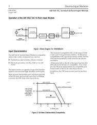
The Programmable Coprocessor Module has a battery and three LEDs. The Series <strong>90</strong>-<strong>70</strong><br />
PCM has two serial port connectors, while the Series <strong>90</strong>-<strong>30</strong> PCM has a single connector<br />
supporting two serial ports. Both the Series <strong>90</strong>-<strong>70</strong> PCM and the Series <strong>90</strong>-<strong>30</strong> PCM have a<br />
Restart/Reset pushbutton.<br />
The three LED indicators, shown in the following figures, are mounted along the top<br />
front edge of the PCM.<br />
MODEL <strong>70</strong><br />
PCM 711<br />
MODULE OK<br />
USER 1<br />
USER 2<br />
ON = OK, ACTIVE<br />
OR USER<br />
PUSH TO RESTART<br />
APPLICATION.<br />
PUSH AND HOLD<br />
TO<br />
STOP AND RESET.<br />
BATTERY<br />
CONNECTIONS<br />
INSTALL NEW<br />
BATTERY BEFORE<br />
UNPLUGGING OLD<br />
BATTERY. USE<br />
IC697ACC<strong>70</strong>1<br />
PORT 1<br />
RS–232 OR<br />
RS–422/RS–485<br />
COMPATIBLE<br />
MODULE FUNCTION<br />
SERIES <strong>90</strong>–<strong>70</strong><br />
PROGRAMMABLE<br />
COPROCESSOR,<br />
COMMUNICATIONS<br />
OPTIONAL MEMORY<br />
USE IC697MEM71<br />
PORT 2<br />
DOOR<br />
PDFsupply.com<br />
RS–232 OR<br />
RS–422/RS–485<br />
COMPATIBLE<br />
a42733<br />
MODULE<br />
IC697PCM711<br />
LABEL<br />
44A726758–203<br />
OPTION CONNECTOR<br />
Figure 1-1. Series <strong>90</strong>-<strong>70</strong> PCM<br />
1-4 Series <strong>90</strong> Programmable Coprocessor Module and Support Software User’s Manual – November 1999 GFK-0255K
1<br />
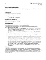
PCM<strong>30</strong>0<br />
COPROC<br />
OK<br />
US1<br />
US2<br />
BD OK<br />
P1 OK<br />
P2 OK<br />
a43734<br />
RESTART<br />
OK LED<br />
BATTERY<br />
Figure 1-2. Series <strong>90</strong>-<strong>30</strong> PCM<br />
The OK LED indicates the current status of the PCM. It has three states:<br />
State<br />
Off<br />
On<br />
Flashing<br />
Description<br />
When the LED is off, the PCM is not functioning. This is the result of a hardware<br />
malfunction, e.g., the diagnostic checks detect a failure, the PCM fails, or the <strong>PLC</strong><br />
CPU is not present. Corrective action is required in order to get the PCM<br />
functioning again.<br />
When the LED is on steadily, the PCM is functioning properly. Normally, this LED<br />
should always be on, indicating that the diagnostic tests were successfully<br />
completed and the configuration data for the module is good.<br />
The LED flashes during power-up diagnostics.<br />
PDFsupply.com<br />
Note<br />
The PCM has a hardware watchdog timer that is periodically reset by<br />
the PCM software. If the watchdog timer expires, the PCM stops<br />
functioning and the OK LED turns off.<br />
GFK-0255K<br />
Chapter 1 <strong>In</strong>troduction<br />
1-5
1<br />
User-Defined LEDs (USER1 and USER2)<br />
The remaining two LED indicators, USER1 and USER2, are user-definable LEDs. By<br />
default, these LEDs blink to indicate activity on the serial ports. USER1 blinks when port<br />
1 sends or receives; USER2 blinks when port 2 sends or receives. The use of either or<br />
both user LEDs may be redefined.<br />
Battery<br />
A lithium battery is installed, as shown in figures 1-1 and 1-2. This battery maintains<br />
user memory when power is removed. Before the battery reaches the end of its useful<br />
life, a low battery fault is reported in the <strong>PLC</strong> fault table. See tables 1-1 and 1-3 for<br />
replacement battery catalog numbers.<br />
When replacing a lithium battery, be sure to connect the new battery into the unused<br />
PCM battery connector before removing and discarding the old battery. Use the<br />
following procedure to replace the battery.<br />
1. Open the front cover. Refer to figures 1-1 and 1-2 for the location of the battery on<br />
the module. (For a new PCM, the battery is not connected.)<br />
Note<br />
When the PCM is to be stored for an extended period of time, the<br />
battery should first be disconnected. However, if it is to be stored as a<br />
spare for a running application, you may wish to retain memory by<br />
leaving the battery connected.<br />
2. Connect the battery to either battery connector on the module. If an old battery is<br />
present, connect the replacement battery to the unused battery connector before<br />
disconnecting the old battery. The tab on the connector should face to the right,<br />
away from the module surface.<br />
3. Press down firmly to lock the battery connector in place, but do not force the battery<br />
connector into place.<br />
Warning<br />
PDFsupply.com<br />
Do not discard the lithium battery in a fire. Do not attempt to recharge<br />
the battery. Do not short the battery. The battery may burst, burn, or<br />
release hazardous materials. Manufacturer’s instructions are available<br />
upon request.<br />
1-6 Series <strong>90</strong> Programmable Coprocessor Module and Support Software User’s Manual – November 1999 GFK-0255K
1<br />
Serial Connectors<br />
The serial connectors on the PCM are used to communicate with external devices, such<br />
as operator interface terminals, bar code readers, and programming devices.<br />
The Series <strong>90</strong>-<strong>70</strong> PCM has two serial connectors; each one supports both RS-232 and<br />
RS-485 operation. The serial ports are identical, and either port can be used for most<br />
applications. The two ports are configurable for different communication parameters.<br />
Note<br />
RS-485 is basically compatible with RS-422 devices.<br />
Series <strong>90</strong>-<strong>30</strong> PCMs have a single serial connector that supports two ports. One port has a<br />
fixed interface. Port 1 uses RS-232 operation only. The 160K PCM, <strong>IC693PCM<strong>30</strong>0</strong> is<br />
restricted to using RS-485 on port 2. All other Series <strong>90</strong>-<strong>30</strong> PCM modules may select<br />
either RS-232 or RS-485 operation on port 2.<br />
Caution<br />
The serial ports on almost all versions of the PCM are connected to<br />
electrical ground within the <strong>PLC</strong>. Serial communication must be<br />
limited to distances of 50 feet (15 meters) unless ground isolation is<br />
provided by an external device. Failure to observe this caution may<br />
result in damage to the PCM or communicating device.<br />
The serial ports on Series <strong>90</strong>-<strong>70</strong> PCMs using PCMA3 or newer<br />
hardware have limited isolation from electrical ground. These ports<br />
can withstand 200 volts DC plus instantaneous peak AC between any<br />
serial port connector pin (except shield) and <strong>PLC</strong> frame ground. This<br />
level of isolation is not adequate for many applications, for example,<br />
communication between devices on different power systems or where<br />
serial cables are exposed to intense electromagnetic fields. For<br />
applications like these, an external optical isolation device should be<br />
installed in the serial connection.<br />
PDFsupply.com<br />
A WYE cable is supplied with each Series <strong>90</strong>-<strong>30</strong> PCM. The purpose of the WYE cable is<br />
to separate the two ports from a single physical connector; i.e., the cable separates the<br />
signals. <strong>In</strong> addition, the WYE cable makes cables used with the Series <strong>90</strong>-<strong>70</strong> PCM fully<br />
compatible with the Series <strong>90</strong>-<strong>30</strong> PCM.<br />
The WYE cable is 1 foot in length and has a right-angle connector on one end that<br />
connects to the PCM. On the other end, it has a dual connector with one connector for<br />
port 1 and the other for port 2.<br />
<strong>In</strong> order to use an RS-232 cable on port 2 of a Series <strong>90</strong>-<strong>30</strong> PCM, either a special cable<br />
must be made according to the serial port pin assignments shown in appendix A or a<br />
WYE cable must be used. Standard Series <strong>90</strong>-<strong>70</strong> PCM cables can be used for the Series<br />
<strong>90</strong>-<strong>30</strong> PCM when the WYE cable is used.<br />
GFK-0255K<br />
Chapter 1 <strong>In</strong>troduction<br />
1-7
1<br />
Caution<br />
The WYE cable should not be used with Series <strong>90</strong>-<strong>30</strong> PCMs connected<br />
to an RS-485 multidrop network because it introduces signal<br />
reflections on the cable. Multidrop networks should be cabled<br />
directly to the PCM serial connector.<br />
The connector pin assignments for the Series <strong>90</strong>-<strong>70</strong> PCM, Series <strong>90</strong>-<strong>30</strong> PCM, and the<br />
WYE cable shipped with each Series <strong>90</strong>-<strong>30</strong> PCM are shown in appendix A, PCM Cabling<br />
<strong>In</strong>formation.<br />
PDFsupply.com<br />
1-8 Series <strong>90</strong> Programmable Coprocessor Module and Support Software User’s Manual – November 1999 GFK-0255K
1<br />
Section 4: Hardware Overview for the Series <strong>90</strong>-<strong>70</strong> PCM<br />
The Series <strong>90</strong>-<strong>70</strong> PCM features include:<br />
A 12.5 mHz 80C186 microprocessor.<br />
128 Kbytes on-board RAM.<br />
Up to 512 Kbytes optional RAM on memory expansion boards. These are the same<br />
expansion boards used by the Series <strong>90</strong>-<strong>70</strong> CPU 731/32 and CPU 771/772.<br />
Two RS-232/RS-485 serial ports.<br />
Backplane access to <strong>PLC</strong> memory.<br />
A real-time calendar clock synchronized to the <strong>PLC</strong>.<br />
A Restart/Reset pushbutton.<br />
Three status LEDs.<br />
Soft configuration (no dip switches or jumpers).<br />
Occupies a single slot in Series <strong>90</strong>-<strong>70</strong> racks.<br />
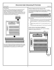
Memory on the Series <strong>90</strong>-<strong>70</strong> PCM consists of PROM, local RAM, and dual port RAM.<br />
PROM contains the operating system, the CCM protocol, a built-in MegaBasic<br />
interpreter, and related utilities. Local RAM is divided into two data areas, one for PCM<br />
internal use and the remainder for the user’s data and programs. Dual port RAM is used<br />
for communications between the PCM and the Series <strong>90</strong>-<strong>70</strong> <strong>PLC</strong> CPU.<br />
DUAL PORT<br />
RAM<br />
( 32K X 16 )<br />
PCM OK LED<br />
USER 1 LED<br />
USER 2 LED<br />
MB PROM<br />
( 64K X 16 )<br />
SYSTEM PROM<br />
( 64K X 16 )<br />
VME<br />
BUS<br />
LOGIC RACK<br />
CONNECTOR<br />
SYSTEM BUS<br />
INTERFACE<br />
NMI<br />
INTI<br />
MICROPROCESSOR<br />
INT. DMA<br />
RS–232/485<br />
SEL<br />
OPTION<br />
CONNECTOR<br />
SERIAL<br />
CONTROLLER<br />
PORT<br />
ONE<br />
INT1<br />
INT3<br />
PORT<br />
TWO<br />
LOCAL<br />
RAM<br />
( 64K X 16 )<br />
a42748<br />
PDFsupply.com<br />
RESET<br />
PB<br />
NMI<br />
LOCAL BUS<br />
Figure 1-3. Series <strong>90</strong>-<strong>70</strong> PCM Hardware Block Diagram<br />
GFK-0255K<br />
Chapter 1 <strong>In</strong>troduction<br />
1-9
1<br />
Two serial ports are provided for communication with a programming terminal, CRTs,<br />
bar code readers, and other devices. These ports are identical in function. On the Series<br />
<strong>90</strong>-<strong>70</strong> PCM, both ports support RS-232 and RS-485 operation through software<br />
configuration.<br />
The PCM has three LED indicators that enable you to determine the state of the PCM<br />
without having a terminal connected. The OK LED (top LED) indicates the current<br />
status of the PCM. The function of the USER1 and USER2 LED indicators (middle and<br />
bottom LEDs, respectively) can be configured by the user program or PCOP. By default,<br />
these LEDs indicate transmit and receive activity on serial ports 1 and 2, respectively.<br />
The option connector on the Series <strong>90</strong>-<strong>70</strong> PCM provides for the addition of expansion<br />
memory. The Series <strong>90</strong>-<strong>30</strong> PCM does not have an option connector.<br />
Table 1-1. Series <strong>90</strong>-<strong>70</strong> PCM Expansion Memory and Accessories<br />
Catalog No.<br />
IC697MEM713<br />
IC697MEM715<br />
IC697MEM717<br />
IC697MEM719<br />
Description<br />
Expansion memory, 64 Kbytes.<br />
Expansion memory, 128 Kbytes.<br />
Expansion memory, 256 Kbytes.<br />
Expansion memory, 512 Kbytes.<br />
IC697ACC<strong>70</strong>1 Replacement battery, package of 2.<br />
IC6<strong>90</strong>CBL<strong>70</strong>1<br />
IC6<strong>90</strong>CBL<strong>70</strong>2<br />
IC6<strong>90</strong>CBL<strong>70</strong>5<br />
PCM to IBM XT compatible 9-pin serial connector.<br />
PCM to IBM AT compatible 9-pin serial connector.<br />
PCM to IBM PS/2 compatible 25-pin serial connector.<br />
PDFsupply.com<br />
1-10 Series <strong>90</strong> Programmable Coprocessor Module and Support Software User’s Manual – November 1999 GFK-0255K
1<br />
Section 5: Hardware Overview for the Series <strong>90</strong>-<strong>30</strong> PCM<br />
The Series <strong>90</strong>-<strong>30</strong> PCM features include:<br />
An 8 mHz 80C188 microprocessor.<br />
On-board RAM, options of 160, 192, or 640 Kbytes.<br />
Two serial ports, one RS-232 and one RS-232/RS-485.<br />
Backplane access to <strong>PLC</strong> memory.<br />
A real-time calendar clock synchronized to the <strong>PLC</strong>.<br />
A Restart/Reset pushbutton.<br />
Three status LEDs.<br />
Soft configuration (no dip switches or jumpers for most users).<br />
Occupies a single slot in the Series <strong>90</strong>-<strong>30</strong> I/O rack.<br />
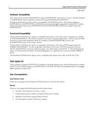
Memory on the Series <strong>90</strong>-<strong>30</strong> PCM consists of PROM and local RAM. PROM contains the<br />
operating system, the CCM protocol, a built-in MegaBasic interpreter, and related<br />
utilities. Local RAM is divided into two data areas, one for PCM internal use and the<br />
remainder for the user’s data and programs.<br />
<strong>90</strong>–<strong>30</strong> RACK<br />
(SERIAL)<br />
LOGIC RACK<br />
CONNECTOR<br />
BACKPLANE<br />
SERIAL<br />
CONTROLLER<br />
PCM OK LED<br />
USER 1 LED<br />
USER 2 LED<br />
RESET<br />
PB<br />
DMA<br />
SYSTEM PROM<br />
256K X 8<br />
( VARIES )<br />
NMI<br />
MICROPROCESSOR<br />
PORT<br />
ONE<br />
SERIAL<br />
CONTROLLER<br />
RS–232/485 SEL<br />
PORT<br />
TWO<br />
LOCAL RAM<br />
192K X 8<br />
( VARIES )<br />
a44362<br />
PDFsupply.com<br />
LOCAL BUS<br />
Figure 1-4. Series <strong>90</strong>-<strong>30</strong> PCM Hardware Block Diagram<br />
GFK-0255K<br />
Chapter 1 <strong>In</strong>troduction<br />
1-11
1<br />
Two serial ports are provided for communication with a programming terminal, CRTs,<br />
bar code readers, and other devices. These ports are identical in function and support<br />
RS-232 and/or RS-485/RS-422 operation through software configuration.<br />
On the Series <strong>90</strong>-<strong>30</strong> PCM, connections to both ports are made through a single 25-pin<br />
D-type connector. A WYE cable is supplied with each PCM module. This cable is 1 foot<br />
in length and has a right-angle connector on one end that connects to the PCM. On the<br />
other end, it has a dual connector with one connector for port 1 and the other for port 2.<br />
The PCM has three LED indicators that enable you to determine the state of the PCM<br />
without having a terminal connected. The OK LED (top LED) indicates the current<br />
status of the PCM. The function of the USER1 and USER2 LED indicators (middle and<br />
bottom LEDs, respectively) can be configured by Logicmaster <strong>90</strong> software, the user<br />
program, or PCOP. By default, these LEDs are used to indicate transmit and receive<br />
activity on serial ports 1 and 2, respectively.<br />
Several versions of the Series <strong>90</strong>-<strong>30</strong> PCM are available. The best one for a particular<br />
application may be selected on the basis of memory and serial port requirements. The<br />
following table lists the PCM versions by catalog number, along with the total RAM<br />
memory available on each module.<br />
Table 1-2. Series <strong>90</strong>-<strong>30</strong> PCM Features<br />
Module Total RAM Port 1 Port 2<br />
<strong>IC693PCM<strong>30</strong>0</strong> 160K RS-232 RS-485<br />
IC693PCM<strong>30</strong>1 192K RS-232 RS-232<br />
RS-485<br />
IC693PCM311 640K RS-232 RS-232<br />
RS-485<br />
Catalog No.<br />
Table 1-3. Series <strong>90</strong>-<strong>30</strong> PCM Accessories<br />
Description<br />
IC693ACC<strong>30</strong>1A Replacement battery, package of 2.<br />
IC693CBL<strong>30</strong>5<br />
IC6<strong>90</strong>CBL<strong>70</strong>1<br />
Series <strong>90</strong>-<strong>30</strong> PCM “WYE” cable.<br />
PCM to IBM XT compatible 9-pin serial connector.<br />
PDFsupply.com<br />
IC6<strong>90</strong>CBL<strong>70</strong>2<br />
IC6<strong>90</strong>CBL<strong>70</strong>5<br />
PCM to IBM AT compatible 9-pin serial connector.<br />
PCM to IBM PS/2 compatible 25-pin serial connector.<br />
1-12 Series <strong>90</strong> Programmable Coprocessor Module and Support Software User’s Manual – November 1999 GFK-0255K
1<br />
Section 6: Configuring the PCM<br />
Before a PCM can be used in a Series <strong>90</strong>-<strong>70</strong> or <strong>90</strong>-<strong>30</strong> <strong>PLC</strong> system, it must be configured<br />
for the CCM or MegaBasic functions it is to perform.<br />
For some CCM-only applications, the Series <strong>90</strong>-<strong>30</strong> PCM requires no configuration at all.<br />
The Model 331, or higher model CPU provides an autoconfig setting for CCM to permit<br />
automatic operation. These autoconfig default settings for the Series <strong>90</strong>-<strong>30</strong> PCM in CCM<br />
mode are described in the next chapter.<br />
Configuration information can be provided in two ways: through Logicmaster <strong>90</strong><br />
configuration (or the Series <strong>90</strong>-<strong>30</strong> Hand-Held Programmer) and/or a user configuration<br />
created by the PCOP development software. For most MegaBasic and CCM<br />
applications, Logicmaster <strong>90</strong> configuration is all that is needed. Logicmaster <strong>90</strong><br />
configuration of the PCM is described in section 2 of the next chapter.<br />
When the PCM is configured for a MegaBasic application by Logicmaster <strong>90</strong> or the Series<br />
<strong>90</strong>-<strong>30</strong> Hand-Held Programmer, PCM batch files may be used to set certain PCM<br />
parameters. PCM batch files are described in appendix D of this manual.<br />
For some advanced applications, the PCM may be configured using the PCOP<br />
development software. The configuration created by PCOP is called User Configuration<br />
Data (UCDF). The UCDF is similar in function to the CONFIG.SYS file in a DOS<br />
personal computer system. The PCM uses the information found in the UCDF to<br />
determine its function. For more information on creating user configuration data, refer<br />
to the Series <strong>90</strong> PCM Development Software (PCOP) User’s Manual, GFK-0487.<br />
Configuring the PCM for CCM Operation<br />
If the PCM is configured for CCM ONLY or BAS/CCM mode using the Logicmaster <strong>90</strong><br />
configuration package, CCM operation is automatically started on the specified port(s)<br />
on power-up or following a soft reset. The configuration of port characteristics (data<br />
rate, etc.), unit ID, and assignment to port 1 or port 2 is also done with the Logicmaster<br />
<strong>90</strong> configuration package.<br />
PDFsupply.com<br />
GFK-0255K<br />
Chapter 1 <strong>In</strong>troduction<br />
1-13
1<br />
Configuring the PCM for MegaBasic Operation<br />
If the PCM has firmware version 2.50 or greater, it may be configured for BASIC or<br />
BAS/CCM mode using Logicmaster <strong>90</strong> software. With these modes, the MegaBasic<br />
program in RAM: automatically loads and starts on power-up or following a soft reset<br />
(pressing the Restart/Reset pushbutton for less than 5 seconds). A hard reset (pressing<br />
the Restart/Reset pushbutton for 10 seconds) will cause MegaBasic to start in PROGRAM<br />
DEVELOPMENT mode. For more information on MegaBasic operation, see chapter 4,<br />
MegaBasic.<br />
Note<br />
PCMs with firmware versions 2.04 and earlier do not recognize BASIC<br />
or BAS/CCM mode. Using one of these modes will cause a fault to be<br />
posted in the <strong>PLC</strong> fault table for the PCM rack and slot location:<br />
“Unsupported feature in configuration.”<br />
Warning<br />
The UCDF, PCM batch files, and MegaBasic program(s) in the PCM<br />
RAM: device are preserved during a <strong>PLC</strong> power loss by the PCM<br />
battery. The Logicmaster <strong>90</strong> configuration is preserved by the <strong>PLC</strong><br />
CPU battery (Series <strong>90</strong>-<strong>70</strong>) or power supply battery (Series <strong>90</strong>-<strong>30</strong>).<br />
Failure to replace either of these batteries when necessary may prevent<br />
the PCM from operating normally.<br />
PDFsupply.com<br />
1-14 Series <strong>90</strong> Programmable Coprocessor Module and Support Software User’s Manual – November 1999 GFK-0255K
1<br />
Section 7: Who Should Use PCOP<br />
Everyone who develops MegaBasic applications for the PCM will need to use either<br />
TERMF or PCOP. (See PCM Support Utilities in section 1 of this chapter for catalog<br />
numbers and brief descriptions of TERMF and PCOP.) TERMF provides a simple<br />
command line interface to the PCM command processor, while PCOP provides a<br />
menu-oriented interface similar to Logicmaster <strong>90</strong> software plus EXPERT mode<br />
shortcuts. PCOP also provides project folder support for multiple PCM applications.<br />
Certain PCM configurations are available only from PCOP; users who need these<br />
configurations must use PCOP. Other users may prefer PCOP. We recommend PCOP<br />
for these users:<br />
CCM application developers who need to adjust CCM timeouts and turnaround<br />
times in finer increments than the ones provided by Logicmaster <strong>90</strong> configuration<br />
must configure the PCM with PCOP.<br />
Note<br />
Beginning with Release 3.00, timeouts and retry counts may be set using<br />
COMMREQs to the CCM task. Refer to the Series <strong>90</strong> <strong>PLC</strong> Serial<br />
Communications User’s Manual, GFK-0582.<br />
Users who already use PCOP, are comfortable with it, and have existing User<br />
Configuration Data (UCDF) Files in their PCMs should continue to use PCOP.<br />
UCDFs can be created and stored to the PCM only by using PCOP.<br />
New users who are uncomfortable with the MS-DOS command line interface in<br />
personal computers will often be more productive using PCOP.<br />
Users who need the PCM command interpreter and file server active on serial port 2<br />
during normal operation (i.e., while MegaBasic is using serial port 1) can set this up<br />
only with PCOP.<br />
Users of PCMs with firmware versions 2.04 and earlier must use PCOP to run<br />
MegaBasic. These users should consider upgrading firmware as an alternative.<br />
Contact the <strong>GE</strong> <strong>Fanuc</strong> <strong>PLC</strong> Technical Support Hotline at 1-800-<strong>GE</strong>FANUC for details.<br />
PDFsupply.com<br />
If you decide to use PCOP, please refer to the Series <strong>90</strong> PCM Development Software User’s<br />
Manual, GFK-0487, and skip section 4, TERMF <strong>In</strong>stallation and Configuration, of chapter 2<br />
in this manual.<br />
GFK-0255K<br />
Chapter 1 <strong>In</strong>troduction<br />
1-15
Chapter<br />
2<br />
2 <strong>In</strong>stalling the PCM<br />
section level 1 1<br />
figure bi level 1<br />
table_big level 1<br />
This chapter explains how to install a Programmable Coprocessor Module (PCM) in a<br />
Series <strong>90</strong> <strong>PLC</strong> system and how to install the necessary software. There are several easy<br />
steps in preparing the PCM for CCM communication or developing and executing a<br />
MegaBasic program.<br />
This chapter is divided into the sections listed below. The necessary equipment and<br />
software packages required for the installation process are included in the following<br />
table. After that, each section describes one step of the installation procedure in detail.<br />
Not all steps are necessary for every application.<br />
Section Title Description Page<br />
1 <strong>In</strong>stalling the PCM<br />
Hardware<br />
2 Configuring the PCM<br />
with Logicmaster <strong>90</strong><br />
Software<br />
3 Configuring the Series<br />
<strong>90</strong>-<strong>30</strong> PCM with the<br />
HHP<br />
4 TERMF <strong>In</strong>stallation<br />
and Configuration<br />
Section 1 contains the first step in the installation<br />
procedure. This step is always requried. It describes<br />
the physical installation of the PCM in a Series <strong>90</strong><br />
rack. Hardware descriptions are also included.<br />
Section 2 contains the second step in the installation<br />
procedure. This step is always required for a Series<br />
<strong>90</strong>-<strong>70</strong> application and for most Series <strong>90</strong>-<strong>30</strong><br />
applications (those not relying on autoconfig.)<br />
It describes how to add a PCM to the Series <strong>90</strong> I/O<br />
configuration, using Logicmaster <strong>90</strong> configuration<br />
software.<br />
The PCM parameters can be edited with the Hand-<br />
Held Programmer if you have a Release 3 or later<br />
CPU and a Release 2.51 or later PCM. Section 3<br />
describes how to do this.<br />
Section 4 describes how to install TERMF software<br />
on a programming computer and configure TERMF<br />
for the computer. This step is required for MegaBasic<br />
programming.<br />
PDFsupply.com<br />
5 Using TERMSET to<br />
Configure TERMF or<br />
PCOP<br />
Section 5 describes how to run TERMSET to modify<br />
the TERM.DAT file. If you are using PCOP, refer to<br />
the Series <strong>90</strong> PCM Development Software (PCOP)<br />
User’s Manual, GFK-0487, for instuctions on installing<br />
PCOP.<br />
2-3<br />
2-6<br />
2-19<br />
2-24<br />
2-26<br />
GFK-0255K<br />
2-1
2<br />
What You Will Need<br />
Before you can begin the installation procedure, you must have the following<br />
equipment:<br />
A Series <strong>90</strong>-<strong>70</strong> programmable controller (<strong>PLC</strong>) system or a Series <strong>90</strong>-<strong>30</strong> <strong>PLC</strong> system<br />
containing a model 331, or higher CPU.<br />
A Programmable Coprocessor Module (PCM) to install and test.<br />
If your application is CCM with standard default settings for a Series <strong>90</strong>-<strong>30</strong> PCM, no<br />
other equipment or software is required.<br />
For other applications, the following is also required:<br />
An MS-DOS based computer with a hard disk and MS-DOS version 3.0 or later. The<br />
computer may be:<br />
A Workmaster II industrial computer.<br />
An IBM PC-XT, PC-AT, industrial PC-AT, or PS/2 personal computer with an<br />
83-key or 101-key keyboard.<br />
A Workmaster or Cimstar I industrial computer with an 83-key or 101-key<br />
keyboard.<br />
Logicmaster <strong>90</strong> programming software.<br />
For most CCM applications, no other equipment or software is required.<br />
For MegaBasic and advanced CCM applications, you also need:<br />
PCM support software (TERMF), IC641SWP063, or PCM development software<br />
(PCOP), IC641SWP061.<br />
One of the standard RS-232 cables described in appendix A, PCM Cabling<br />
<strong>In</strong>formation.<br />
PDFsupply.com<br />
2-2 Series <strong>90</strong> Programmable Coprocessor Module and Support Software User’s Manual – November 1999 GFK-0255K
2<br />
Section 1: <strong>In</strong>stalling the PCM Hardware<br />
The first step in the installation procedure is to physically install the PCM hardware and<br />
verify that it is working properly.<br />
Overview<br />
<strong>In</strong> a single rack system, the PCM resides in the same rack as the <strong>PLC</strong> CPU. <strong>In</strong> a multiple<br />
rack Series <strong>90</strong>-<strong>70</strong> <strong>PLC</strong>, the PCM can reside in either the CPU rack or an expansion rack.<br />
The Series <strong>90</strong>-<strong>30</strong> PCM must reside in the main rack with the CPU.<br />
The following illustration shows two possible system configurations for installing a<br />
Series <strong>90</strong>-<strong>70</strong> PCM in either a local or expansion rack.<br />
LOCAL RACK CONFIGURATION<br />
P<br />
S<br />
C P<br />
U<br />
P<br />
CM<br />
CPU RACK<br />
EXPANSION RACK<br />
P<br />
S C B P<br />
P TM S<br />
B P<br />
R CM<br />
U M<br />
Figure 2-1. Series <strong>90</strong>-<strong>70</strong> PCM Configurations<br />
a42732<br />
PDFsupply.com<br />
The power supply, CPU, and Series <strong>90</strong>-<strong>70</strong> Bus Transmitter (BTM) or Bus Receiver Module<br />
(BRM) must reside in specific slots within each rack. The CPU module must be located<br />
in slot 1 of rack 0.<br />
The Series <strong>90</strong>-<strong>70</strong> system usually includes a Bus Transmitter Module (BTM). The Bus<br />
Transmitter Module may be located in any slot as long as it is not to the right of an<br />
empty slot. If the <strong>PLC</strong> system has more than one rack, a Bus Receiver Module (BRM)<br />
must be located in slot 1 of each expansion rack.<br />
Note<br />
Version A of the Bus Transmitter Module must be installed to the right of<br />
all other <strong>GE</strong> <strong>Fanuc</strong> modules. There must be no empty slots between the<br />
Bus Transmitter Module and the CPU module.<br />
GFK-0255K<br />
Chapter 2 <strong>In</strong>stalling the PCM<br />
2-3
2<br />
The Programmable Coprocessor Module (PCM) may be placed in any unused slot in any<br />
rack, provided that these conditions are met:<br />
<strong>In</strong>stalling a Series <strong>90</strong>-<strong>70</strong> PCM<br />
The configuration created by Logicmaster <strong>90</strong> configuration software must match the<br />
physical configuration of the modules. If it does not, the <strong>PLC</strong> may not operate as<br />
expected. Configuration faults are logged in the <strong>PLC</strong> fault table. Refer to the<br />
Logicmaster <strong>90</strong> Programming Software User’s Manual, GFK-0263 or GFK-0466, for more<br />
information on <strong>PLC</strong> configuration using Logicmaster <strong>90</strong> software.<br />
When PCMs are installed in a Series <strong>90</strong>-<strong>70</strong> rack, all the slots between the PCM and<br />
the <strong>PLC</strong> CPU (CPU rack) or the Bus Receiver Module (expansion rack) must be<br />
occupied. If any of these slots is empty, the PCM cannot communicate across the<br />
backplane to the Series <strong>90</strong>-<strong>70</strong> <strong>PLC</strong> CPU or Bus Receiver Module.<br />
A Series <strong>90</strong>-<strong>30</strong> PCM must be in the main rack with the <strong>PLC</strong> CPU.<br />
To install a Series <strong>90</strong>-<strong>70</strong> PCM, follow these steps:<br />
1. Set the CPU Run/Stop switch to STOP. This prevents the <strong>PLC</strong> program from<br />
initiating any command that may affect the operation of the module.<br />
2. Power down the Series <strong>90</strong>-<strong>70</strong> <strong>PLC</strong> system.<br />
3. Locate the desired rack and slot.<br />
4. Remove the Series <strong>90</strong>-<strong>70</strong> PCM from the shipping carton, but leave it in its anti-static<br />
plastic bag. Touch an exposed metal surface of the <strong>PLC</strong> rack to discharge any<br />
electrostatic charge you may have picked up. Then remove the PCM from the<br />
protective bag.<br />
5. Slide the PCM completely into the slot. The three LEDs are located at the top of the<br />
module.<br />
6. Press the module firmly against the front rails of the <strong>PLC</strong> rack, but do not use<br />
excessive force.<br />
7. Power up the <strong>PLC</strong> rack. The OK LED (top LED) on the faceplate flashes during<br />
power-up diagnostics. It continues to flash while waiting for configuration data<br />
from the CPU. If no signal is received across the backplane for 2 minutes, the PCM<br />
assumes that the CPU is not there and continue to power up without it. Once the<br />
PCM is ready, this LED should be continuously on.<br />
PDFsupply.com<br />
<strong>In</strong>stalling a Series <strong>90</strong>-<strong>30</strong> PCM<br />
To install a Series <strong>90</strong>-<strong>30</strong> PCM, follow these steps:<br />
1. Use Logicmaster <strong>90</strong> software or the Hand Held Programmer to stop the <strong>PLC</strong>. This<br />
prevents the <strong>PLC</strong> program from initiating any command that may affect the<br />
operation of the module.<br />
2. Power down the Series <strong>90</strong>-<strong>30</strong> <strong>PLC</strong> system.<br />
3. Locate the desired rack and slot.<br />
4. Hook the top of the PCM case to the <strong>PLC</strong> baseplate and then guide the latch on the<br />
bottom of the case into its slot in the baseplate. The three LEDs are located at the<br />
top of the module.<br />
2-4 Series <strong>90</strong> Programmable Coprocessor Module and Support Software User’s Manual – November 1999 GFK-0255K
2<br />
5. Press down firmly to lock the module in place, but do not use excessive force.<br />
6. Power up the <strong>PLC</strong> rack. The OK LED (top LED) on the faceplate of the PCM begins<br />
to flash during power-up diagnostics if a <strong>PLC</strong> CPU has been installed in the rack.<br />
When the PCM successfully completes diagnostics, it continues to flash while<br />
waiting for configuration data from the CPU. Once the PCM is ready, this LED<br />
should be continuously on.<br />
Adding Expansion Memory to the Series <strong>90</strong>-<strong>70</strong> PCM<br />
To increase the total available memory, an expansion memory daughter board may be<br />
added to a Series <strong>90</strong>-<strong>70</strong> PCM. The daughter board mounts on a single connector on the<br />
PCM. Expansion memory cannot be added to a Series <strong>90</strong>-<strong>30</strong> PCM.<br />
Four versions of the expansion memory board are available:<br />
Table 2-1. Expansion Memory Boards<br />
Catalog Number<br />
Memory Size<br />
IC697MEM713 64K Bytes<br />
IC697MEM715 128K Bytes<br />
IC697MEM717 256K Bytes<br />
IC697MEM719 512K Bytes<br />
To mount the daughter board, follow these steps:<br />
1. Touch an exposed metal surface of the <strong>PLC</strong> rack in order to discharge any<br />
electrostatic charge you may have.<br />
2. Power down the Series <strong>90</strong>-<strong>70</strong> <strong>PLC</strong> system, and remove the PCM.<br />
3. Remove the memory expansion module from its anti-static bag.<br />
4. Carefully align the pins on the bottom side of the daughter board with the connector<br />
on the PCM.<br />
5. Align the holes on the opposite end of the PCM with the daughter board standoffs.<br />
6. Push the daughter board into the connector.<br />
PDFsupply.com<br />
7. Make sure the daughter board is fully seated and the standoffs are snapped into<br />
both boards.<br />
If an expansion memory board is installed on a PCM that has already been configured<br />
for no expansion memory or for a different expansion memory size, the Logicmaster <strong>90</strong><br />
configuration must be updated and stored to the <strong>PLC</strong> CPU.<br />
GFK-0255K<br />
Chapter 2 <strong>In</strong>stalling the PCM<br />
2-5
2<br />
Section 2: Configuring the PCM with Logicmaster <strong>90</strong> Software<br />
The second step in the PCM installation procedure is to add a PCM to the Series <strong>90</strong> I/O<br />
configuration, using Logicmaster <strong>90</strong> configuration software. The configuration software<br />
is used to describe the modules present in the <strong>PLC</strong> racks. Rack and slot location and<br />
other features for individual modules are specified by completing setup screens that<br />
represent the modules in a rack. Editing features make it easy to copy, move, replace, or<br />
delete module configurations.<br />
After completing the Logicmaster <strong>90</strong> configuration, you must store it to the <strong>PLC</strong> where<br />
your PCM is installed. The configuration has no effect until it is stored to the <strong>PLC</strong>. The<br />
Logicmaster <strong>90</strong> status line must display CONFIG EQUAL after the configuration is<br />
stored to the <strong>PLC</strong>.<br />
I/O Configuration Rack Screen<br />
Note<br />
For a Series <strong>90</strong>-<strong>30</strong> PCM using standard CCM default operation, this step<br />
is not required. Refer to the information on autoconfig at the end of this<br />
section for information on the default CCM operation.<br />
From the main menu of the Logicmaster <strong>90</strong> configuration software, press I/O (F1). A<br />
screen representing the modules in a rack is displayed.<br />
This example represents a Series <strong>90</strong>-<strong>70</strong> <strong>PLC</strong> rack.<br />
PDFsupply.com<br />
2-6 Series <strong>90</strong> Programmable Coprocessor Module and Support Software User’s Manual – November 1999 GFK-0255K
2<br />
This example represents a Series <strong>90</strong>-<strong>30</strong> <strong>PLC</strong> Model 331 rack.<br />
The current module on a Series <strong>90</strong> I/O Configuration rack screen is highlighted in<br />
reverse video. Upon entering the rack screen, the Power Supply module is shown in<br />
reverse video. Use the left or right cursor keys to move from module to module. Use<br />
the up and down cursor keys to move between racks in descending or ascending order,<br />
respectively.<br />
The rack screen presents an overview perspective of one Series <strong>90</strong> <strong>PLC</strong> rack. To add a<br />
PCM, press Other (F8) and then PCM (F1). To display the current configuration of the<br />
module in a slot, press Zoom (F10).<br />
CONFIG VALID is displayed in the lower right corner of each display screen after the<br />
configuration is successfully validated. When CONFIG INVALID is indicated, the<br />
configuration may not be stored to the <strong>PLC</strong>. A CONFIG INVALID status is most likely<br />
to occur when:<br />
PDFsupply.com<br />
A slot in a Series <strong>90</strong>-<strong>70</strong> rack to the left of a module that generates interrupts, such as<br />
the PCM, is vacant.<br />
<strong>In</strong>put reference addresses (%I and %AI) overlap.<br />
Bus Transmitter and/or Receiver Modules in a multi-rack Series <strong>90</strong>-<strong>70</strong> <strong>PLC</strong> are<br />
missing.<br />
A Series <strong>90</strong>-<strong>70</strong> Version A BTM module is not located to the right of all other modules.<br />
GFK-0255K<br />
Chapter 2 <strong>In</strong>stalling the PCM<br />
2-7
2<br />
Adding a PCM to the Rack Screen<br />
A PCM must first be entered before its memory expansion board may be selected. To do<br />
this, follow these steps:<br />
1. Press Other (F8) and then PCM (F1) from the I/O Rack Configuration screen.<br />
2. Press the Enter key to enter the catalog number shown in reverse video and display<br />
the PCM detail screen.<br />
PDFsupply.com<br />
2-8 Series <strong>90</strong> Programmable Coprocessor Module and Support Software User’s Manual – November 1999 GFK-0255K
2<br />
3. To enter a Memory Expansion board (for Series <strong>90</strong>-<strong>70</strong> systems only), press Expansion<br />
Board (F9) and then Memory (F1). The following list is displayed.<br />
PCM Configuration Data<br />
4. Cursor to the desired catalog number, and press the Enter key.<br />
5. After selecting the desired memory expansion board, press the Escape key to return<br />
to the PCM detail screen.<br />
After selecting the module and the expansion memory, the PCM is configured for CCM<br />
and/or MegaBasic operation from the PCM module detail screen. The PCM<br />
configuration mode is selected from the Config Mode field on the detail screen.<br />
To select a different configuration mode, repeatedly press the Tab key until the desired<br />
mode is displayed on the screen. Then, press the Enter key. Use the Cursor and Tab<br />
keys to complete the detail screen for the desired configuration mode, and press the<br />
Enter key.<br />
PDFsupply.com<br />
Once the PCM has been configured, press the Escape key again to save the module<br />
configuration and return to the rack display. The display screen should now include the<br />
PCM in the slot you selected. Complete the configuration procedure for each module<br />
you wish to add to the Series <strong>90</strong> <strong>PLC</strong> rack.<br />
Once the Series <strong>90</strong> system configuration is complete, Logicmaster <strong>90</strong> software is used to<br />
store the configuration to the <strong>PLC</strong> CPU. If the PCM configuration has changed since the<br />
last configuration store, the PCM is automatically reset and restarts using the new<br />
configuration.<br />
GFK-0255K<br />
Chapter 2 <strong>In</strong>stalling the PCM<br />
2-9
2<br />
PCM Configuration Modes<br />
Before configuring the PCM with Logicmaster <strong>90</strong> software, it is necessary to understand<br />
the various configuration modes and how they affect the operation of the PCM. Each<br />
mode is described in the table below. Many PCM applications use one of three<br />
configuration modes: CCM ONLY, BASIC, or BAS/CCM. Some applications use PCM<br />
CFG, PROG PRT, PROG/CCM, or CCM/PROG. These modes all require that the PCM<br />
itself be configured using the PCOP software package.<br />
Mode<br />
CCM ONLY<br />
BASIC<br />
BAS/CCM<br />
Table 2-2. PCM Configuration Modes<br />
Description<br />
CCM ONLY mode permits complete configuration for CCM execution on one<br />
or both PCM ports. After a soft reset, the PCM automatically starts CCM on<br />
the designated port(s).<br />
BASIC mode is used to configure the PCM for a standard MegaBasic<br />
application. The ports are configured for use by the MegaBasic program and<br />
for connection to the TERMF package (port 1), which is used to program the<br />
MegaBasic application. The program must be saved to the PCM RAM Disk<br />
(RAM:) as “BASIC.PGM”. After a soft reset, the PCM automatically starts the<br />
MegaBasic program. BASIC mode is not available in Release 2 of Logicmaster<br />
<strong>90</strong>-<strong>70</strong> software. This mode is not supported by PCM firmware version 2.04 or<br />
earlier.<br />
BAS/CCM mode is similar to BASIC mode, except that port 2 is configured for<br />
CCM execution and is, therefore, not available to the MegaBasic application<br />
program. After a soft reset, the PCM automatically starts the MegaBasic<br />
program, along with CCM on port 2. BAS/CCM mode is not available in<br />
Release 2 of Logicmaster <strong>90</strong>-<strong>70</strong> software. This mode is not supported by PCM<br />
firmware version 2.04 or earlier.<br />
NONE NONE is only used when the PCM does not support Logicmaster <strong>90</strong><br />
configuration, as for a Release 1 PCM. NONE mode is only available in<br />
Logicmaster <strong>90</strong>-<strong>70</strong> software.<br />
PCM CFG<br />
PROG PRT<br />
PROG/CCM<br />
CCM/PROG<br />
PCM CFG indicates that all configuration data for the PCM is selected using<br />
PCOP and loaded to the PCM as User Configuration Data (UCDF) or that a<br />
PCMEXEC.BAT file specifies the configuration to be used.<br />
PROG PRT is a special mode used to configure port settings for the PCM<br />
without automatically running a MegaBasic program or CCM. PROG PRT<br />
mode is selected for special applications using PCOP for configuration. The<br />
serial port configuration specified with this mode becomes effective only after<br />
a hard reset or if no other configuration exists on the PCM.<br />
PDFsupply.com<br />
PROG/CCM and CCM/PROG modes are a combination of CCM on one port<br />
and PCOP program part settings on the other port.<br />
Note<br />
If User Configuration Data (UCDF) has been loaded to the PCM from<br />
PCOP, the UCDF configuration is used after a power cycle or soft reset.<br />
The Logicmaster <strong>90</strong> configuration is ignored. The PCOP CLEAR<br />
command or MDE (Module Delete) command can be used to delete<br />
the UCDF from the PCM.<br />
2-10 Series <strong>90</strong> Programmable Coprocessor Module and Support Software User’s Manual – November 1999 GFK-0255K
2<br />
CCM ONLY Mode<br />
When CCM ONLY mode is selected, the PCM is used only for CCM operation on one or<br />
both ports. When this mode is selected in Logicmaster <strong>90</strong> software, the following PCM<br />
detail screen is displayed.<br />
Parameter<br />
Configuration Mode<br />
Battery Required<br />
Set to CCM ONLY.<br />
Description<br />
Specify whether a battery is required. Choices are YES* or NO.<br />
CCM Enable Specify whether the port is to be configured for use as a CCM port.<br />
Choices are YES* or NO.<br />
CCM Mode This parameter displays the availability of ports for CCM access.<br />
Choices are SLAVE*, PEER, or MASTER.<br />
<strong>In</strong>terface The interface parameter for port 1 of a Series <strong>90</strong>-<strong>30</strong> PCM is RS-232; port 2<br />
of the 192K and 640K Series <strong>90</strong>-<strong>30</strong> modules may have an interface value<br />
of either RS-232* or RS-485. The interface parameter is not used or<br />
displayed for the 160K module, <strong>IC693PCM<strong>30</strong>0</strong>. RS-232* and RS-485<br />
are valid for both ports of the Series <strong>90</strong>-<strong>70</strong> PCM.<br />
PDFsupply.com<br />
Data Rate<br />
Flow Control<br />
Parity<br />
Retry Count<br />
Timeout<br />
Turnaround Delay<br />
CPU ID<br />
* Default selection.<br />
Data rate (bits per second or bps) for the port.<br />
Choices are <strong>30</strong>0, 600, 1200, 2400, 4800, 9600, or 19200*.<br />
Type of flow control to be used for the port.<br />
Choices are HARDWARE or NONE*.<br />
Type of parity to be used for the port. Choices are NONE or ODD*.<br />
Retry counts for CCM mode. Choices are NORMAL* or SHORT.<br />
Length of timeouts used for CCM on the port.<br />
Choices are LONG*, MEDIUM, SHORT, or NONE.<br />
Turnaround delay time to be used for CCM on the port.<br />
Choices are NONE*, 10 ms, 100 ms, or 500 ms.<br />
Address of the port on a multi-drop network. This value is used to<br />
calculate the backoff delay upon an inquiry collision in peer mode. The<br />
range of values allowed in this field is 1* to 254. A different value<br />
must be selected for each CCM device on the network.<br />
GFK-0255K<br />
Chapter 2 <strong>In</strong>stalling the PCM<br />
2-11
2<br />
BASIC Mode<br />
Warning<br />
BASIC mode is not supported in PCM firmware version 2.04 or earlier.<br />
Attempting to use it will result in an “Unsupported feature in<br />
configuration” fault for the PCM in the <strong>PLC</strong> fault table.<br />
When BASIC mode is selected, the PCM automatically runs a MegaBasic program<br />
named BASIC.PGM, if it exists. CCM operation is not started on either port. When this<br />
mode is selected in Logicmaster <strong>90</strong> software, the following PCM detail screen is<br />
displayed.<br />
Parameter<br />
Configuration Mode<br />
<strong>In</strong>terface<br />
Set to BASIC.<br />
Description<br />
PDFsupply.com<br />
The interface parameter for port 1 of a Series <strong>90</strong>-<strong>30</strong> PCM is RS-232;<br />
port 2 of the 192K and 640K Series <strong>90</strong>-<strong>30</strong> modules may have an interface<br />
value of either RS-232* or RS-485. The interface parameter is not<br />
used or displayed for the 160K module, <strong>IC693PCM<strong>30</strong>0</strong>. RS-232* and<br />
RS-485 are valid for both ports of the Series <strong>90</strong>-<strong>70</strong> PCM.<br />
Data Rate Data rate (bits per second or bps) for the port. Choices are <strong>30</strong>0, 600,<br />
1200, 2400, 4800, 9600, or 19200*. The Series <strong>90</strong>-<strong>70</strong> PCM also<br />
supports 38400.<br />
Flow Control<br />
Parity<br />
Type of flow control to be used for the port.<br />
Choices are HARDWARE*, SOFTWARE, or NONE.<br />
Type of parity to be used for the port. Choices are NONE*, ODD, or EVEN.<br />
Stop Bits The number of stop bits for the part. Choices are 1* or 2.<br />
Bits per Character<br />
* Default selection.<br />
The number of bits per character for data transfer on the port.<br />
Choices are 7 or 8*.<br />
2-12 Series <strong>90</strong> Programmable Coprocessor Module and Support Software User’s Manual – November 1999 GFK-0255K
2<br />
BAS/CCM Mode<br />
Warning<br />
BAS/CCM mode is not supported in PCM firmware version 2.04 or<br />
earlier. Attempting to use it will result in an “Unsupported feature in<br />
configuration” fault for the PCM in the <strong>PLC</strong> fault table.<br />
When BAS/CCM mode is selected, the PCM automatically runs a MegaBasic program<br />
named BASIC.PGM, if it exists, on port 1 and CCM on port 2. When this mode is<br />
selected in the Logicmaster <strong>90</strong> software, the following PCM detail screen is displayed.<br />
The configuration mode is set to BAS/CCM. The remainder of configurable parameters<br />
are as described previously for BASIC mode on port 1 and CCM mode on port 2.<br />
PDFsupply.com<br />
GFK-0255K<br />
Chapter 2 <strong>In</strong>stalling the PCM<br />
2-13
2<br />
PCM CFG and NONE Modes<br />
When PCM CFG or NONE mode is selected in Logicmaster <strong>90</strong> software, there are no<br />
other parameters on the detail screen to be set. These modes require configuration data<br />
stored in the PCM. Either a PCMEXEC.BAT file or User Configuration Data (UCDF)<br />
may be used. For information on PCMEXEC.BAT files, see appendix D, PCM Batch Files.<br />
UCDFs are created and stored to a PCM using the PCOP development software. For<br />
more information on PCOP and UCDFs, see the Series <strong>90</strong> PCM Development Software<br />
(PCOP) User’s Manual, GFK-0487. When one of these modes is selected, the PCM uses<br />
its default serial port settings unless they have been overridden by the PCMEXEC.BAT<br />
or UCDF configuration.<br />
An example detail screen showing NONE mode is displayed below. The detail screen<br />
for PCM CFG mode is identical to this.<br />
PDFsupply.com<br />
2-14 Series <strong>90</strong> Programmable Coprocessor Module and Support Software User’s Manual – November 1999 GFK-0255K
2<br />
PROG PRT Mode<br />
PROG PRT mode is used to configure the PCM ports without automatically configuring<br />
the PCM for MegaBasic or CCM operation. This mode requires configuration data<br />
stored in the PCM. Either a PCMEXEC.BAT file or User Configuration Data (UCDF)<br />
may be used. For information on PCMEXEC.BAT files, see appendix D, PCM Batch Files.<br />
UCDFs are created and stored to a PCM using the PCOP development software. For<br />
more information on PCOP and UCDFs, see the Series <strong>90</strong> PCM Development Software<br />
(PCOP) User’s Manual, GFK-0487. PROG PRT mode is similar to PCM CFG mode and<br />
NONE mode but permits specifying serial port settings which are different from the<br />
default. However, the Logicmaster <strong>90</strong> serial port settings will be overridden by the<br />
PCMEXEC.BAT or UCDF configuration data, if any.<br />
Typically, use of this mode is to insure that port 2 has the same setup when PCM is in<br />
factory mode (hard reset) as when PCM is in user mode (soft reset). This is useful when<br />
developing MegaBasic programs that use port 2. When this mode is selected in<br />
Logicmaster <strong>90</strong> software, the following PCM detail screen is displayed.<br />
Parameter<br />
Configuration Mode<br />
Set to PROG PRT.<br />
Description<br />
PDFsupply.com<br />
<strong>In</strong>terface<br />
The interface parameter for port 1 of a Series <strong>90</strong>-<strong>30</strong> PCM is RS-232;<br />
port 2 of the 192K and 640K Series <strong>90</strong>-<strong>30</strong> modules may have an interface<br />
value of either RS-232* or RS-485. The interface parameter is not<br />
used or displayed for the 160K module, <strong>IC693PCM<strong>30</strong>0</strong>. RS-232* and<br />
RS-485 are valid for both ports of the Series <strong>90</strong>-<strong>70</strong> PCM.<br />
Data Rate Data rate (bits per second or bps) for the port. Choices are <strong>30</strong>0, 600,<br />
1200, 2400, 4800, 9600, or 19200*. The Series <strong>90</strong>-<strong>70</strong> PCM also<br />
supports 38400.<br />
Flow Control<br />
Parity<br />
Type of flow control to be used for the port.<br />
Choices are HARDWARE*, SOFTWARE, or NONE.<br />
Type of parity to be used for the port. Choices are NONE*, ODD, or EVEN.<br />
Stop Bits The number of stop bits for the target port. Choices are 1* or 2.<br />
Bits per Character<br />
* Default selection.<br />
The number of bits per character for data transfer on the target port.<br />
Choices are 7 or 8*.<br />
GFK-0255K<br />
Chapter 2 <strong>In</strong>stalling the PCM<br />
2-15
2<br />
PROG/CCM and CCM/PROG Modes<br />
PROG/CCMand CCM/PROG modes are used to configure the PCM programming and<br />
CCM ports without automatically configuring the PCM for MegaBasic operation. These<br />
modes require configuration data atored in the PCM. Either a PCMEXEC.BAT file or<br />
User Configuration Data (UCDF) may be used. For information on PCMEXEC.BAT files,<br />
see appendix D, PCM Batch Files. UCDFs are created and stored to a PCM using the<br />
PCOP development software. For more information on PCOP and UCDFs, see the<br />
Series <strong>90</strong> PCM Development Software (PCOP) User’s Manual, GFK-0487.<br />
When PROG/CCM this mode is selected in Logicmaster <strong>90</strong> software, the following PCM<br />
detail screen is displayed.<br />
The configuration mode is set to PROG/CCM. The remainder of configurable parameters<br />
are as described previously for PROG PRT mode on port 1 and CCM ONLY mode on<br />
port 2.<br />
The screen displayed for CCM/PROG mode is similar. It shows CCM port options in the<br />
Port 1 column and PROG options in the Port 2 column.<br />
PDFsupply.com<br />
2-16 Series <strong>90</strong> Programmable Coprocessor Module and Support Software User’s Manual – November 1999 GFK-0255K
2<br />
Configuration Modes and the PCOP Display<br />
When the PCOP development software is running and connected to a PCM, it attempts<br />
to display the current PCM operating mode on its status line. The following table shows<br />
the modes displayed by PCOP for various combinations of Logicmaster <strong>90</strong> configuration<br />
modes, presence or absence of UCDF configurations, and reset conditions. A soft reset<br />
occurs when the PCM Reset/Restart pushbutton is pressed and held for less than 5<br />
seconds. A hard reset occurs when the button is held for 10 seconds.<br />
Table 2-3. Logicmaster <strong>90</strong> Configuration Mode<br />
Configuration Present Soft Reset Hard Reset<br />
Logicmaster <strong>90</strong> Mode Mode<br />
Configuration Configuration Displayed Configuration Displayed<br />
Mode UCDF Used by PCOP Used by PCOP<br />
NONE None Factory Default FACTORY Factory Default FACTORY<br />
PCM CFG None Factory Default FACTORY Factory Default FACTORY<br />
CCM ONLY None LM<strong>90</strong> CCM Config LM CFG Factory Default FACTORY<br />
PROG PRT None Factory Default LM CFG Factory Default FAC MOD<br />
LM<strong>90</strong> PROG Port Def<br />
LM<strong>90</strong> PROG Port Def<br />
PROG/CCM None LM<strong>90</strong> CCM Config LM CFG Factory Default FAC MOD<br />
LM<strong>90</strong> PROG Port Def<br />
NONE Yes PCM User Config USER Factory Default FACTORY<br />
PCM CFG Yes PCM User Config USER Factory Default FACTORY<br />
CCM ONLY Yes PCM User Config USER Factory Default FACTORY<br />
PROG PRT Yes PCM User Config USER Factory Default FAC MOD<br />
LM<strong>90</strong> PROG Port Def<br />
PROG/CCM Yes PCM User Config USER Factory Default FAC MOD<br />
CCM/PROG<br />
LM<strong>90</strong> PROG Port Def<br />
Note that BASIC and BAS/CCM modes have been omitted from the table. When<br />
MegaBasic is started by the Logicmaster <strong>90</strong> configuration, PCOP will display either LM<br />
CFG when it can communicate with the PCM or NO COMM when it cannot.<br />
PDFsupply.com<br />
GFK-0255K<br />
Chapter 2 <strong>In</strong>stalling the PCM<br />
2-17
2<br />
Series <strong>90</strong>-<strong>30</strong> PCM Autoconfig<br />
The Series <strong>90</strong>-<strong>30</strong> <strong>PLC</strong> Model 331, or higher CPU provides automatic default<br />
configuration called Autoconfig for many of the system modules.<br />
The configuration provided for the Series <strong>90</strong>-<strong>30</strong> PCM is similar to configuring the PCM in<br />
Logicmaster <strong>90</strong>-<strong>30</strong> software for CCM ONLY mode. Thus, if Logicmaster <strong>90</strong>-<strong>30</strong> software<br />
has not been used to configure the Model 331, or higher CPU system, the Series <strong>90</strong>-<strong>30</strong><br />
PCM can still be plugged into the rack and will communicate to a CCM device.<br />
<strong>In</strong> order to initiate the autoconfig default settings, either clear the <strong>PLC</strong> or delete the PCM<br />
slot from the Logicmaster <strong>90</strong>-<strong>30</strong> configuration and then read it with the Hand-Held<br />
Programmer.<br />
The default values for autoconfig, listed in the following table, are the same as the<br />
default configuration values provided by the Logicmaster <strong>90</strong>-<strong>30</strong> software in CCM ONLY<br />
mode.<br />
Table 2-4. Autoconfig Default Configuration Values<br />
Port 1 Port 2<br />
CCM Enable Yes CCM Enable Yes<br />
CCM Mode Slave CCM Mode Slave<br />
<strong>In</strong>terface RS-232 <strong>In</strong>terface RS-422/RS-485<br />
Data Rate 19200 Data Rate 19200<br />
Flow Control None Flow Control None<br />
Parity Odd Parity Odd<br />
Retry Count Normal Retry Count Normal<br />
Timeout Long Timeout Long<br />
TurnA Delay None TurnA Delay None<br />
CPU ID 1 CPU ID 1<br />
To change any of the default configuration values provided or to use a different mode<br />
for the Series <strong>90</strong>-<strong>30</strong> PCM, you must use Logicmaster <strong>90</strong>-<strong>30</strong> software, PCOP, or both to<br />
configure the PCM. To use PCOP, refer to the Series <strong>90</strong> PCM Development Software<br />
(PCOP) User’s Manual, GFK-0487.<br />
PDFsupply.com<br />
Note<br />
If you have Release 3.00 or later <strong>PLC</strong> CPU and Release 2.50 or later<br />
PCM, the Hand-Held Programmer (HHP) may also be used to configure<br />
the PCM. Refer to the section 3 for more information on using the<br />
Hand-Held Programmer.<br />
2-18 Series <strong>90</strong> Programmable Coprocessor Module and Support Software User’s Manual – November 1999 GFK-0255K
2<br />
Section 3: Configuring the Series <strong>90</strong>-<strong>30</strong> PCM with the HHP<br />
Freezing the Configuration<br />
Programmable Coprocessor Module parameters can be edited with the Hand-Held<br />
Programmer if you have a Release 3 or later CPU and a Release 2.51 or later PCM. The<br />
parameters are edited in exactly the same manner as for <strong>In</strong>telligent I/O Modules<br />
described previously in this chapter.<br />
Processing a change to the PCM’s configuration takes 15 seconds or more. Processing<br />
multiple parameter changes simultaneously takes the same time as processing a change<br />
to a single parameter. Since changing several parameters at once is a common<br />
occurrence, changes to individual parameters are remembered by the module but are<br />
not processed and do not take effect until specifically commanded to do so.<br />
When a PCM parameter is changed, an asterisk (*) will appear before the module name<br />
on the top line of the HHP screen. This indicates that the module’s previous<br />
configuration has been “frozen”, and that the module is not yet using the change(s) you<br />
have just made. You can continue editing, and this and all subsequent changes will be<br />
remembered by the module. However, if power is lost while a module’s configuration is<br />
frozen, the changes (edits) you have made made will be lost.<br />
When the configuration for a module is frozen in this manner, you can tell the system<br />
that editing of all of the parameters is complete by pressing the WRITE and ENT keys.<br />
The edited changes are then processed all at once by the PCM and the asterisk will<br />
disappear from the display, indicating that the new values are being used by the PCM<br />
and have been saved in the <strong>PLC</strong>’s non-volatile memory.<br />
If you decide to abandon the changes that you have made so far, they can be discarded<br />
by pressing the CLR and ENT keys. If you do this, the configuration parameters will<br />
revert to the values they had before the configuration was frozen.<br />
If you attempt to leave the current slot (either by pressing the , –, or # key) while the<br />
module’s configuration is frozen, you will be prompted to indicate whether to use the<br />
new combination of values, discard the new values and return to the old configuration,<br />
or to continue editing the changes. If you attempt to change the HHP mode or go to<br />
RUN mode, the “FROZEN” error message will be displayed.<br />
Note<br />
PDFsupply.com<br />
Once changes have been made which are not being used by the<br />
module, you cannot leave the slot until the changes are saved or<br />
discarded.<br />
GFK-0255K<br />
Chapter 2 <strong>In</strong>stalling the PCM<br />
2-19
2<br />
Example of Editing a PCM<br />
For this example, assume that a 192K PCM (IC693PCM<strong>30</strong>1) module resides in slot 2 of<br />
the CPU rack and that the <strong>PLC</strong> was powered up with the CLR and M/T keys depressed<br />
(that is, the <strong>PLC</strong> was cleared). <strong>In</strong> our example, we want to change the mode from CCM<br />
only (the default) to PROGRAMMER PORT and to change the data rate for both ports to<br />
9600 baud.<br />
<strong>In</strong>itial display:<br />
To view the mode parameter:<br />
Press the<br />
key:<br />
To view other possible modes,<br />
Press the<br />
- +<br />
key:<br />
R0:02 PCM<strong>30</strong>1
2<br />
To refresh the display of the module name, press any key, for example:<br />
Press the<br />
ENT<br />
key:<br />
R0:02*PCM<strong>30</strong>1
2<br />
To change the port 1 baud rate to 9600:<br />
Press the<br />
- +<br />
key:<br />
R0:02*PCM<strong>30</strong>1
2<br />
To continue the example, suppose that you start changing parameters, then realize that<br />
you have made a mistake. The changes made so far (that is, since the configuration was<br />
frozen) can be discarded, reverting to the previous configuration.<br />
Change the baud rate parameter for port 2 to 4800:<br />
Press the<br />
- +<br />
ENT<br />
key sequence:<br />
R0:02*PCM<strong>30</strong>1
2<br />
Section 4: TERMF <strong>In</strong>stallation and Configuration<br />
<strong>In</strong>stalling TERMF<br />
<strong>In</strong> order to use your personal computer to program the PCM, TERMF or PCOP must be<br />
installed and then configured. This section describes how to install TERMF on your<br />
computer and how to use TERMSET, the configuration program for TERMF and PCOP.<br />
For information on installing PCOP, refer to the PCOP Quick Reference Guide, GFK-0657,<br />
in the front of this manual, or to the Series <strong>90</strong> PCM Development Software (PCOP) User’s<br />
Manual, GFK-0487.<br />
The PCM support software package, TERMF (IC641SWP063), includes one 5.25-inch and<br />
one 3.5-inch installation diskette. Choose the diskette that fits a diskette drive in your<br />
computer.<br />
1. Select the TERMF installation diskette which fits your computer’s A drive and place<br />
it in your computer. TERMF must be installed from drive A.<br />
A. To install TERMF to hard drive C, type a:install at the MS-DOS prompt and<br />
press the Enter key.<br />
B. If your computer has more than one hard drive or your hard drive is partitioned<br />
into two or more logical drives, you can install TERMF to hard drive D or E<br />
rather than C. To install TERMF to hard drive D, type a:install d: and<br />
press the Enter key at the MS-DOS prompt.<br />
2. The TERMF installation program creates these directories on the specified hard drive<br />
if they do not already exist:<br />
\PCOP<br />
\PCOP\EXAMPLES.PCM<br />
\PCOP\UTILS<br />
The files listed in appendix F, TERMF File Descriptions, are copied to these<br />
directories. If a previous version of TERMF or PCOP was already on the hard drive<br />
before this installation, there may be additional files in these directories. Any files<br />
that are not listed in appendix F may be deleted from the hard disk in order to<br />
conserve storage space.<br />
PDFsupply.com<br />
3. The CLEANUP batch file in the \PCOP directory may be used to delete<br />
unnecessary files. To use it, be sure that the hard drive where TERMF is installed is<br />
the current drive. Then, type the following at the MS-DOS prompt:<br />
CD \PCOP<br />
CLEANUP<br />
2-24 Series <strong>90</strong> Programmable Coprocessor Module and Support Software User’s Manual – November 1999 GFK-0255K
2<br />
Adding the PCOP Directory to the MS-DOS Search Path<br />
The MS-DOS operating system in your computer uses a search path to find programs<br />
that are not in the current directory. The PCOP directory should be added to the search<br />
path so that TERMF and TERMSET can be used without typing the name of the<br />
directory where they are stored.<br />
The MS-DOS PATH command may be used to determine what directories are currently<br />
in the search path. The PATH command can also be used to add the PCOP directory to<br />
the search path.<br />
To determine what directories are currently in the search path, type path at the<br />
MS-DOS prompt and press the Enter key. MS-DOS will display a list of the directories,<br />
separated by semicolons, in the current search path on your computer’s display. If no<br />
search path has been defined, the words No Path are displayed on the screen. If the<br />
PCOP directory is not already included in the search path, it should be added.<br />
The search path is defined in the AUTOEXEC.BAT file, located in the root directory of<br />
the disk drive from which MS-DOS is started (the boot drive, which is usually drive C).<br />
Using any text editor program, edit the \AUTOEXEC.BAT file. If the file does not<br />
contain a path command similar to path=c:\dos, add the following command as the<br />
first line of the file:<br />
path=c:\pcop<br />
If there is already a PATH command, add this text at the end of the path definition:<br />
;c:\pcop<br />
If TERMF was not installed on the C drive, use the correct drive letter in place of “c”.<br />
If there is no AUTOEXEC.BAT file in the root directory of the boot drive, create one<br />
with your text editor. <strong>In</strong>clude only a PATH command, as above, which specifies the<br />
PCOP directory on the correct hard drive.<br />
Note<br />
PDFsupply.com<br />
The AUTOEXEC.BAT file may begin with an ECHO OFF command in<br />
the first line. If one is present, the PATH command should appear in<br />
the second line.<br />
GFK-0255K<br />
Chapter 2 <strong>In</strong>stalling the PCM<br />
2-25
2<br />
Section 5: Using TERMSET to Configure TERMF or PCOP<br />
Before TERMF or PCOP can be used to program the PCM, it requires information about<br />
the display hardware in your computer and the serial port settings to be used for<br />
communication with the PCM. This information is provided by a data file named<br />
TERM.DAT. A default version of TERM.DAT, installed with TERMF or PCOP, contains<br />
display hardware settings for the Workmaster industrial computer from <strong>GE</strong> <strong>Fanuc</strong>.<br />
These settings will work with any computer that uses an IBM Color Graphics Adapter<br />
(CGA) display. The default TERM.DAT also contains serial port settings identical to the<br />
PCM default settings.<br />
If your computer uses different display hardware, such as the IBM Monochrome Display<br />
Adapter (MDA), Enhanced Graphics Adapter (EGA) or Video Graphics Array (VGA), you<br />
need to use the TERMSET program. If you change your computer’s hardware<br />
configuration, you will need to use TERMSET again. You also need to run TERMSET in<br />
order to use PCM serial port settings that are different from the defaults. TERMSET asks<br />
you about your computer’s display hardware and the serial port settings you plan to<br />
use; then it makes the necessary changes to the TERM.DAT file.<br />
The file DEFAULT.DAT contains the same default settings as the initial version of<br />
TERM.DAT installed with TERMF.<br />
Caution<br />
The file DEFAULT.DAT should never be modified. It is very useful<br />
when troubleshooting for providing default settings to TERMF or<br />
PCOP.<br />
To run TERMSET:<br />
1. Type CD \PCOP at the MS-DOS prompt.<br />
2. To make changes to the TERM.DAT file, type TERMSET to display the TERMSET<br />
main menu. There are three parts to the main menu: Basic Setup, Custom<br />
Configurations, and Exit TERMSET. To configure TERMF or PCOP for your<br />
computer, you need to use only the two Basic Setup functions (items 3 and 4, below)<br />
to set up the serial port and display adapter. For information on Custom<br />
Configurations, see items 5 through 8 on the following pages.<br />
PDFsupply.com<br />
3. To change the serial port settings, first type 1 to display the current values. Then<br />
type the number corresponding to the setting to be changed. A new menu will<br />
appear, showing all possible values for the selected setting. Choose one of the<br />
values from this menu. Be sure the new port settings match the configuration of the<br />
PCM port used for programming. When all the settings are correct, type E to<br />
return to the main menu.<br />
4. To change the video adapter (display hardware) settings, type 2. If the display<br />
settings are correct, answer N to the prompt to avoid changing them. Generally, the<br />
display adapter type is the only setting that should need to be changed. If it is<br />
incorrect, type Y. An explanation of the display parameters is provided in the<br />
following table.<br />
2-26 Series <strong>90</strong> Programmable Coprocessor Module and Support Software User’s Manual – November 1999 GFK-0255K
2<br />
Value<br />
Video Adapter Type<br />
Description<br />
Specifies the type of display adapter your personal computer<br />
uses to drive the attached video monitor (CRT). The six<br />
hardware selections are:<br />
1 = Enhanced Graphics Adapter/Video Graphics Array<br />
(EGA/VGA).<br />
Display Page Length<br />
Display Control Sequences<br />
Normal Display Video Mode<br />
Display Long Lines<br />
Character Font<br />
2 = Color Graphics Adapter (CGA)<br />
(e.g. Workmaster computer). *<br />
3 = Good CGA without snow<br />
(i.e. a non-IBM CGA-compatible adapter).<br />
4 = Monochrome Display Adapter (MDA).<br />
5 = Vega 7 Deluxe/Multisync (using VEGABIOS.SYS).<br />
6 = EGA driving a Monochrome Display.<br />
Specifies the number of lines to be displayed on one video<br />
page. Range = 10 - 60 lines (Default = 25).<br />
Display control character sequences from the PCM. Choices are<br />
ENABLED or DISABLED*. If display is enabled, control<br />
sequences are visible but have no effect. If display is disabled,<br />
control sequences perform their intended functions.<br />
Controls character width and color/monochrome features of the<br />
display. Range is normally 0 - 3 and 7. Recommended values<br />
are:<br />
3 = Color display (video adapter type 1, 2, 3, or 5). *<br />
7 = Monochrome display (video adapter type 4 or 6).<br />
Specifies whether TERMF will honor the Set 132 column escape<br />
sequence, 3h. Choices are ENABLED or DISABLED*.<br />
It is recommended that you disable this feature unless you<br />
have a display adapter and driver software that interpret one of<br />
the two video modes listed above to display a 120 or 132-column<br />
screen. If you enable this selection, a second option allows<br />
you to specify which display mode represents your long-lines<br />
display mode.<br />
This selection is valid only for EGA/VGA adapters with the<br />
capability of using a user-loaded character font for text display.<br />
The four font selections are:<br />
1 = Normal font in ROM*. This allows for 25 lines of text<br />
per screen.<br />
PDFsupply.com<br />
2 = Double dot font in ROM. This allows 43 to 50 lines of<br />
text per screen.<br />
3 = User specified 256-character font. This allows 10 to 60<br />
lines of text per screen and up to 256 user-defined<br />
characters.<br />
* Default selection.<br />
4 = User specified 512-character font. This allows 10 to 60<br />
lines of text per screen and up to 512 user-defined<br />
characters in two font files of 256 characters each. The<br />
font sizes in the two files must be the same.<br />
GFK-0255K<br />
Chapter 2 <strong>In</strong>stalling the PCM<br />
2-27
2<br />
When all the display settings are correct, return to the main menu by typing N (or<br />
any key except Y) at the prompt that asks whether you want to change the settings.<br />
Then type E to save the changes and exit from TERMSET. If you do not want to<br />
save the new settings, type Q.<br />
<strong>In</strong> addition to the settings previously described, some custom configuration options<br />
are available from the TERMSET main menu. These options are seldom, if ever,<br />
used with TERMF or PCOP. They are included here to help you configure TERMF as<br />
a general purpose terminal emulation program for use with serial devices other than<br />
the PCM. These options are explained in the remainder of this section.<br />
5. Item 3 in the TERMSET main menu selects a screen that describes the keyboard<br />
input queue, special key handling, multi-character transmission delay, size of the<br />
received character buffer, key assignments for exiting from TERMF and for sending a<br />
break from the serial port, and the delay count which determines the length of the<br />
break. To change any of these parameters, type Y. A short explanation of each<br />
parameter is given below:<br />
Value<br />
Keyboard <strong>In</strong>put<br />
Queue<br />
Special Key<br />
Handling<br />
Options include:<br />
Description<br />
Supplied by BIOS*: The capability to type ahead is limited to 15<br />
characters. This mode is reliable on every computer. It is strongly<br />
recommended.<br />
Supplied by program: The capability to type ahead is expanded to 255<br />
characters. This mode is not reliable on all computers, and is not<br />
recommended.<br />
Special keys include the function keys, ALT keys, and keypad keys,<br />
which have a “key binding” associated with them.<br />
Sent as character sequences from key bindings: When a key is pressed,<br />
the appropriate key binding sets are searched for that key. If found, the<br />
keystroke is translated accordingly. With TERMF in cursor mode, all<br />
three sets (cursor, application, and normal) are searched in that order.<br />
<strong>In</strong> application mode, only application and normal sets are searched;<br />
in normal mode, only the normal key binding set is searched.<br />
PDFsupply.com<br />
Multi-character<br />
Transmission Delay<br />
* Default selection.<br />
Sent as MegaBasic control characters*: When a key is pressed, a search<br />
is first performed in a predefined set of MegaBasic key bindings. (Refer<br />
to the MegaBasic Programming Language Reference Manual, GFK-0256.)<br />
The MegaBasic key bindings are designed to allow the same use of<br />
special keys for MegaBasic in both the PCM and a personal computer.<br />
If the keystroke does not match a MegaBasic key binding, translation is<br />
performed as described in the preceding option (sent as character<br />
sequences from key bindings).<br />
This delay value is arbitrary and varies among different computer models.<br />
It is a count of the number of times a software delay loop is repeated<br />
before putting the next character into the transmit buffer. This parameter<br />
is used only when TERMF is communicating with very slow devices.<br />
It is included here only for the sake of completeness. The PCM does not<br />
require this delay. Range = 0* to 32,767. The value zero (0) is strongly<br />
recommended.<br />
2-28 Series <strong>90</strong> Programmable Coprocessor Module and Support Software User’s Manual – November 1999 GFK-0255K
2<br />
Value<br />
Received Character<br />
Buffer Size<br />
Exit Term Key<br />
Send Break Key<br />
Break Delay<br />
Show Scan Code<br />
* Default selection.<br />
Description<br />
This buffer size affects the overall speed of TERMF when flow control is<br />
enabled. With no flow control, it affects the probability that a received<br />
character may be lost. It also affects the responsiveness of the display<br />
when a key is pressed: the smaller the buffer, the more responsive.<br />
If you use the Scroll Lock key to start and stop continuous output from a<br />
device, a 1000-character buffer is recommended. If you are simply starting<br />
and stopping a MegaBasic listing from the PCM using the space bar, then<br />
a 100-character buffer* is adequate.<br />
This selection changes the key combination which exits from TERMF. The<br />
default setting, 2092*, assigns ALT-Z. (Press the Z key while holding the<br />
ALT key.) You can also exit from TERMF by using the CTRL-BREAK key<br />
combination.<br />
The scan codes used for this setting do not correspond to keyboard scan<br />
codes documented in IBM personal computer manuals. Use Show Scan<br />
Code, below, to determine the correct setting for the key or key<br />
combination (Shift, CTRL or ALT plus another key) you select.<br />
Do not change this setting if you use PCOP. The Series <strong>90</strong> PCM<br />
Development Software (PCOP) User’s Manual, GFK-0487, specifies ALT-Z as<br />
the key combination to return to PCOP after communicating with PCM<br />
MegaBasic. If you change this setting, PCOP will not function as expected.<br />
This selection changes the key combination which causes TERMF to send<br />
a serial break. The default setting, 2152*, assigns ALT-F1. (Press the F1<br />
function key while holding ALT.)<br />
The scan codes used for this setting do not correspond to keyboard scan<br />
codes documented in IBM personal computer manuals. Use Show Scan<br />
Code, described below, to determine the correct setting for the key or key<br />
combination (Shift, CTRL or ALT plus another key) you select.<br />
PCM MegaBasic does not respond to Break, although user programs can.<br />
This delay value is arbitrary and varies among different computer models.<br />
It is a count of the number of times a software delay loop is repeated<br />
between the start and end of a break. The default is 20,000* counts.<br />
This menu item is shown after you answer Y to the prompt that asks<br />
whether you wish to change a selection. You should use Show Scan Code<br />
to discover the scan code for the key or key combination you want to<br />
assign to the Send Break function or exit TERMF.<br />
Caution<br />
PDFsupply.com<br />
The key assignment for exiting from TERMF should never be changed<br />
when using PCOP. A change to this setting will prevent PCOP from<br />
functioning as expected.<br />
When these selections are correct, type N.<br />
GFK-0255K<br />
Chapter 2 <strong>In</strong>stalling the PCM<br />
2-29
2<br />
6. Menu item 4 selects a screen that displays the current values for display attributes.<br />
These values select the foreground and background colors for characters based on<br />
the status of the graphics rendition modes reverse, intensify, underline, and blink.<br />
This selection allows you to change the colors of the display used by TERMF and<br />
PCOP. The values are coded as two hexadecimal digits representing a string of eight<br />
bits. The three least significant bits (1 through 3) code the foreground color; bit 4<br />
specifies high intensity; bits 5 through 7 code the background color; and bit 8<br />
specifies blinking.<br />
TERMSET shows the names of the colors which correspond to the numeric values<br />
selected for foreground and background colors. These are the colors displayed on<br />
CGA, EGA and VGA color displays. If your computer has a monochrome display,<br />
you should use the default display attributes.<br />
To redefine any of the display attributes, type Y and respond to the prompts for<br />
attribute combination number and hexadecimal attribute value. When the settings<br />
are correctly displayed, type N.<br />
7. Menu items 5, 6, and 7 select screens that display the scan codes contained in the<br />
normal, application, and cursor key binding sets, respectively. Key bindings are used<br />
to redefine keys for various operational modes. A single keystroke may send up to<br />
80 characters via these key bindings.<br />
Note<br />
Custom key bindings have limited value when using TERMF or PCOP<br />
with the PCM. This description is provided only for completeness.<br />
When using MegaBasic special key handling, only ordinary keys (i.e.,<br />
those that produce a non-null character code can be used for<br />
keybindings. For example, CTRL-A can be used to produce the<br />
character code 1.<br />
If MegaBasic special key handling is selected from main menu item 3, many of these<br />
custom binding in these sets will be replaced with MegaBasic defaults.<br />
To view or modify the normal key bindings, type Y, select the appropriate function,<br />
and answer the prompts:<br />
1 Look at a table entry.<br />
2 Replace a table entry.<br />
3 Delete a table entry.<br />
4 Add a table entry.<br />
5 Show the scan code for the key.<br />
PDFsupply.com<br />
When the key bindings are correct, type N.<br />
8. Menu item 8 selects a screen which displays the current values for the display color<br />
palette settings. These settings are only available for EGA/VGA adapters. The EGA<br />
color palette has 16 entries. The colors are defined in RGB notation (i.e., three digits<br />
with values 0 to 3 each to indicate the intensity of Red (first digit), Green (second<br />
digit), and Blue (third digit). The range for each color is 000 to 333, giving a palette<br />
of 64 possible colors.<br />
If you wish to change any of these settings, type Y and respond to the prompts for<br />
register number, RGB value, and color name. If the settings are correct as displayed,<br />
type N.<br />
2-<strong>30</strong> Series <strong>90</strong> Programmable Coprocessor Module and Support Software User’s Manual – November 1999 GFK-0255K
2<br />
Local Configuration File<br />
If you frequently use more than one TERMF or PCOP setup, you can save each<br />
configuration in its own file. You can specify the local configuration file by naming it<br />
when you invoke TERMSET, as follows:<br />
TERMSET [new filename]<br />
For example, to switch between using an EGA and monochrome display, type:<br />
COPY DEFAULT.DAT TERM.EGA<br />
TERMSET TERM.EGA<br />
and modify the default settings to use your EGA display. When you exit from TERMSET,<br />
these settings are saved to the file TERM.EGA. Then, create a file named TERM.MON to<br />
describe the monochrome display by typing:<br />
COPY DEFAULT.DAT TERM.MON<br />
TERMSET TERM.MON<br />
Whenever you need to change your configuration to the EGA setup, type:<br />
Or, for the monochrome monitor, type:<br />
COPY TERM.EGA TERM.DAT or PCOP<br />
TERMF<br />
COPY TERM.MON TERM.DAT or PCOP<br />
TERMF<br />
You could also specify which file to use when you invoke TERMF or PCOP, as follows:<br />
PDFsupply.com<br />
TERMF TERM.EGA or PCOP TERM.EGA or<br />
TERMF TERM.MON or PCOP TERM.MON<br />
GFK-0255K<br />
Chapter 2 <strong>In</strong>stalling the PCM<br />
2-31
2<br />
Connecting the PCM to the Programmer<br />
Cables for connecting the PCM to a display terminal or personal computer are described<br />
in appendix A, PCM Cabling <strong>In</strong>formation. To connect the PCM to the programmer:<br />
1. Connect the cable between the PCM programmer port (usually port 1) and the serial<br />
port on the VT100 or OIT terminal or IBM PC-XT, PC-AT, PS/2, Workmaster,<br />
Workmaster II, or Cimstar I industrial computer.<br />
If you are using a computer as the programmer, be sure the cable is connected to the<br />
serial port (COM1 or COM2) specified by TERM.DAT. If you are using PCOP, refer<br />
to the Series <strong>90</strong> PCM Development Software (PCOP) User’s Manual, GFK-0487, for<br />
additional information on establishing communication with the PCM.<br />
2. If you are using a computer as the programmer, type TERMF at the MS-DOS<br />
prompt and press the Enter key.<br />
3. Press the PCM Restart/Reset pushbutton for 10 seconds to initiate a hard reset and<br />
place the PCM in programming (factory) mode.<br />
4. If the PCM has firmware version 2.50 or greater and has been configured using<br />
Logicmaster <strong>90</strong> software for BASIC or BAS/CCM mode, the MegaBasic banner<br />
should be displayed at the top of the screen, followed by the “Ready” prompt.<br />
MegaBasic Version 5.602, under PCM VTOS v2.50<br />
IEEE/Software floating point on an 80186/88 CPU<br />
(c)Copyright 1985–19<strong>90</strong> by Christopher Cochran<br />
MegaBasic Support BBS: 415–459–0896, PO Box 723<br />
Fairfax, CA. USA 949<strong>30</strong> – Serial #0000<br />
Ready<br />
With other Logicmaster <strong>90</strong> configuration modes, you should see a “-> ” prompt from<br />
the PCM command interpreter. If your PCM has firmware version 2.04 or lower, you<br />
must use PCOP to program the PCM.<br />
PDFsupply.com<br />
VT100 is a trademark of Digital Equipment Corporation.<br />
2-32 Series <strong>90</strong> Programmable Coprocessor Module and Support Software User’s Manual – November 1999 GFK-0255K
2<br />
Diagnosing Serial Communication Problems<br />
Before proceeding, verify that the OK LED on the PCM is on. If the LED is off, refer to<br />
the information in section 1 of this chapter.<br />
This procedure is used to determine if there is a hardware problem with the<br />
programmer serial ports.<br />
1. Verify that both the PCM and the programmer are using the same baud rate, parity,<br />
number of data bits, number of stop bits, and the same type of handshaking<br />
( HARDWARE, SOFTWARE, or NONE ).<br />
Note<br />
If you configured the PCM using Logicmaster <strong>90</strong> software, review<br />
section 2 of this chapter. If you used the Series <strong>90</strong>-<strong>30</strong> Hand-Held<br />
Programmer, review section 3 of this chapter. When verifying the<br />
programmer serial port configuration, review section 5 of this chapter.<br />
2. Verify that the cable connections, described in appendix A, PCM Cabling <strong>In</strong>formation,<br />
are correct and that the cable is firmly secured at both ends.<br />
3. Press the PCM Restart/Reset pushbutton for 10 seconds. The middle light on the<br />
PCM should blink. If it does not, remove the connector from the PCM, jumper pins<br />
4 and 5 on the PCM with a paper clip, and press the Reset/Restart pushbutton again<br />
for 10 seconds. If the LED still does not blink at least once, there is a problem with<br />
the PCM. Otherwise, the cable, programmer configuration, or programmer<br />
hardware is the problem; continue with step 4.<br />
4. Reconnect the cable to the PCM. If the programmer has more than one serial port,<br />
be sure the cable is connected to COM1. Set the programmer serial port to the PCM<br />
default settings. To do this when using a computer as the programmer, type TERMF<br />
DEFAULT.DAT at the MS-DOS prompt and press the Enter key.<br />
5. Press and hold the Restart/Reset pushbutton for 10 seconds to initialize the PCM to<br />
its factory default settings.<br />
6. Press the programmer Enter key while watching the USER1 LED for serial port 1 or<br />
USER2 LED for serial port 2. Each time the key is pressed the LED should blink. If<br />
the PCM has been configured by Logicmaster <strong>90</strong> in BASIC or BAS/CCM mode, the<br />
“Ready” prompt should also be repeated on the programmer screen; otherwise the<br />
“> ” prompt should appear. If the LED does not blink or the “Ready” or “> ” prompt<br />
is not displayed, either the connection from the programmer to the PCM is bad or<br />
the programmer hardware is defective.<br />
PDFsupply.com<br />
7. Cycle power on the programmer to make sure its serial port hardware is fully reset.<br />
Problems with the programmer are very rare. When they do occur, they can often<br />
be fixed with a power cycle. If your programmer is a computer, type TERMF<br />
DEFAULT.DAT again. If the LED still does not blink when a key is pressed, it is<br />
likely that there is a problem with the cable. See appendix A, PCM Cabling<br />
<strong>In</strong>formation, for information on PCM cables. Occasionally, problems occur with the<br />
PCM or PC serial port hardware.<br />
8. Press CTRL-BREAK or ALT-Z to exit TERMF.<br />
If PCOP establishes communication with the PCM but the PCOP status never switches<br />
to ONLINE, refer to the Series <strong>90</strong> PCM Development Software (PCOP) User’s Manual,<br />
GFK-0487, for additional suggestions.<br />
GFK-0255K<br />
Chapter 2 <strong>In</strong>stalling the PCM<br />
2-33
Chapter<br />
3<br />
3 CCM Operation<br />
section level 1 1<br />
figure bi level 1<br />
table_big level 1<br />
This chapter contains information relevant to the operation of the CCM communication<br />
protocol on the Series <strong>90</strong> PCM. The PCM must be configured for CCM operation, using<br />
Logicmaster <strong>90</strong> configuration software or PCOP, before attempting CCM<br />
communication. Refer to chapter 2, section 2 of this manual for a guide to configuring<br />
the PCM.<br />
This chapter contains the following sections:<br />
Section Title Description Page<br />
1 Series <strong>90</strong> CCM Target<br />
Memory Types<br />
2 Series <strong>90</strong> CCM<br />
Memory Addressing<br />
Conventions<br />
3 Communications<br />
Request<br />
(COMMREQ)<br />
4 CCM COMMREQ<br />
Data Block<br />
5 CCM COMMREQ<br />
Status Word<br />
Section 1 defines the memory types for the Series <strong>90</strong><br />
<strong>PLC</strong>. Memory allocation for the CCM scratch pad<br />
and diagnostic status words is also described in this<br />
section.<br />
Section 2 explains the addressing conventions and<br />
data lengths for each memory type.<br />
Section 3 describes the Communications Request<br />
(COMMREQ) function.<br />
Section 4 describes the CCM COMMREQ data<br />
block and includes a summary of the data blocks for<br />
the Series <strong>90</strong> command set.<br />
Section 5 describes the status word returned by a<br />
CCM COMMREQ. Also included is a table of return<br />
status error codes.<br />
PDFsupply.com<br />
6 CCM COMMREQ<br />
Example<br />
7 <strong>PLC</strong> System<br />
Communications<br />
Window<br />
Section 6 provides a complete Series <strong>90</strong> <strong>PLC</strong> ladder<br />
logic program containing CCM COMMREQ function<br />
blocks for the PCM. The sample program is suitable<br />
for both Series <strong>90</strong>-<strong>30</strong> and Series <strong>90</strong>-<strong>70</strong> <strong>PLC</strong>s.<br />
Section 7 describes the effect this configurable portion<br />
of the Series <strong>90</strong>-<strong>70</strong> <strong>PLC</strong> CPU execution sweep can<br />
have on CCM communication. Also included is how<br />
to adjust the window time from the <strong>PLC</strong> program.<br />
3-2<br />
3-7<br />
3-12<br />
3-19<br />
3-23<br />
3-25<br />
3-28<br />
Comparisons of the CCM implementations in Series <strong>90</strong> , Series Six , Series Five ,<br />
and Series One <strong>PLC</strong>s are included in sections 1 and 2 of this chapter to assist those<br />
who are already experienced in the operation of CCM on other <strong>GE</strong> <strong>Fanuc</strong> programmable<br />
logic controllers. If you need information on Series <strong>90</strong> CCM only, skip to section 3 of this<br />
chapter.<br />
GFK-0255K<br />
3-1
3<br />
Section 1: Series <strong>90</strong> CCM Target Memory Types<br />
Series <strong>90</strong> CCM supports a subset of the memory types available in Series Six CCM.<br />
Tables 3-1 and 3-2 below list the Series <strong>90</strong> CCM memory types. The types for the CCM<br />
single bit write function (listed in table 3-2) are functional memory types. They map to<br />
the same input and output tables as memory types 1 and 2, but are assigned unique<br />
memory type numbers because they are used to perform bit set and bit clear special<br />
operations on the input and output tables.<br />
Table 3-1. Memory Types Supported by Series <strong>90</strong> CCM<br />
CCM Memory Type<br />
CCM Target Table<br />
1 Register Table (%R)<br />
2 <strong>In</strong>put Table (%I)<br />
3 Output Table (%Q)<br />
6 CCM Scratch Pad<br />
9 Diagnostic Status Words<br />
Table 3-2. Memory Types for the CCM Single Bit Write Function (6110)<br />
CCM Memory Type CCM Target Table Bit Operation<br />
13 <strong>In</strong>put Table (%I) Bit Set<br />
14 Output Table (%Q) Bit Set<br />
17 <strong>In</strong>put Table (%I) Bit Clear<br />
18 Output Table (%Q) Bit Clear<br />
Those Series Six memory types that are not supported are listed in the following table.<br />
Table 3-3. Series Six Memory Types NOT Supported by Series <strong>90</strong> CCM<br />
PDFsupply.com<br />
CCM Memory Type CCM Target Table Bit Operation<br />
0 Absolute –<br />
4 <strong>In</strong>put Override Table –<br />
5 Output Override Table –<br />
7 User Logic –<br />
8 Quick Access Buffer –<br />
10 Timers –<br />
11 Counters –<br />
15 <strong>In</strong>put Override Table Bit Set<br />
16 Output Override Table Bit Set<br />
19 <strong>In</strong>put Override Table Bit Clear<br />
20 Output Override Table Bit Clear<br />
21 <strong>In</strong>put Override Table Bit Toggle<br />
22 Output Override Table Bit Toggle<br />
3-2 Series <strong>90</strong> Programmable Coprocessor Module and Support Software User’s Manual – November 1999 GFK-0255K
3<br />
The next two tables compare the Series One and Series Five CCM memory types with<br />
those supported by the Series <strong>90</strong> CCM.<br />
Table 3-4. Series One Memory Types vs. Series <strong>90</strong> CCM Memory Types<br />
Series One CCM<br />
Series <strong>90</strong> CCM<br />
Memory Type Target Table Memory Type Target Table<br />
1 Timer/Counter/DataRegister 1 Register Table<br />
3 Discrete I/O 1 2, 3 <strong>In</strong>put Table, Output Table<br />
6 Scratch Pad 2 6 CCM Scratch Pad<br />
7 User Logic Not Supported<br />
9 Diagnostic Status Words 3 9 Diagnostic Status Words<br />
1 The addressing scheme for the Series One <strong>PLC</strong> differs from that of the Series <strong>90</strong> <strong>PLC</strong> when accessing<br />
I/O points. Refer to the next section for more information.<br />
2 Scratch pad definitions are not the same in the Series One <strong>PLC</strong> and the Series <strong>90</strong> <strong>PLC</strong>.<br />
See table 3-6 for the Series <strong>90</strong> scratch pad layout.<br />
3 Diagnostic status words and error code definitions are different in the Series One <strong>PLC</strong> and the Series <strong>90</strong><br />
<strong>PLC</strong>. See table 3-7 for the Series <strong>90</strong> diagnostic status words, and refer to table 3-12 for the Series <strong>90</strong> CCM<br />
error code definitions.<br />
Table 3-5. Series Five Memory Types vs. Series <strong>90</strong> CCM Memory Types<br />
Series Five CCM<br />
Series <strong>90</strong> CCM<br />
Memory Type Target Table Memory Type Target Table<br />
1 Registers 1 Register Table<br />
2 <strong>In</strong>puts 1.3 2 <strong>In</strong>put Table<br />
3 Outputs 2,3 3 Output Table<br />
6 Scratch Pad 4 6 CCM Scratch Pad<br />
7 User Logic Not Supported<br />
9 Diagnostic Status Words 5 9 Diagnostic Status Words<br />
1 The Series Five local and special inputs do not exist in the Series <strong>90</strong> input table. All inputs are<br />
equivalent, and it is up to you to determine their functionality.<br />
2 The Series Five local and internal outputs do not exist in the Series <strong>90</strong> output table. All outputs are<br />
equivalent, and it is up to you to determine their functionality. For example, an output to be used<br />
as an internal coil must not be tied to a real output.<br />
3 The addressing scheme for the Series Five <strong>PLC</strong> differs from that of the Series <strong>90</strong> <strong>PLC</strong> when accessing<br />
I/O points. Refer to the next section for more information.<br />
4 Scratch pad definitions are not the same in the Series Five <strong>PLC</strong> and Series <strong>90</strong> <strong>PLC</strong>. See table 3-6 for<br />
the Series <strong>90</strong> scratch pad layout.<br />
5 Diagnostic status words and error code definitions are different in the Series Five <strong>PLC</strong> and the Series<br />
<strong>90</strong> <strong>PLC</strong>. See table 3-7 for the Series <strong>90</strong> diagnostic status words, and refer to table 3-12 for the Series <strong>90</strong><br />
CCM error code definitions.<br />
PDFsupply.com<br />
GFK-0255K<br />
Chapter 3 CCM Operation<br />
3-3
3<br />
CCM Scratch Pad<br />
The entire scratch pad is updated every time an external READ request is received by<br />
CCM with a memory type of 6. All scratch pad locations are read only. The scratch pad<br />
is a byte-oriented memory type.<br />
Table 3-6. Scratch Pad Memory Allocation<br />
SP Address Field Identifier 7 6 5 4 3 2 1 0<br />
Bits<br />
00 CPU Run Status 0 0 0 0 See Note (1)<br />
01 CPU Command Status Bit pattern same as SP(00)<br />
02 CPU Type Major 2a (in hexadecimal)<br />
03 Minor 2b (in hexadecimal)<br />
04 – 0B CPU ID 7 ASCII characters + termination character = 0<br />
0C CPU Firmware Revision No. Major (in BCD)<br />
0D<br />
Minor (in BCD)<br />
0E PCM Firmware Revision No. Major<br />
0F<br />
Minor<br />
10 – 11 Reserved (00H)<br />
12 3a Node Type Identifier (<strong>90</strong>-<strong>70</strong>: 0CH; <strong>90</strong>-<strong>30</strong>: 0DH) 3b<br />
13 – 15 Reserved (00H)<br />
Master/Slave: 1 – <strong>90</strong> (decimal)<br />
16 CCM CPU ID Peer-to-Peer: 1 – 254<br />
Universal Responder: 255<br />
17 Reserved (00H)<br />
18 – 33 Sizes of Memory Types See Note (4)<br />
18 – 1B Register Memory %R size<br />
1C – 1F Analog <strong>In</strong>put Table %AI size<br />
20 – 23 Analog Output Table %AQ size<br />
24 – 27 <strong>In</strong>put Table %I size<br />
28 – 2B Output Table %Q size<br />
2C – 2F <strong>In</strong>ternal Discrete Memory %M size<br />
<strong>30</strong> – 33 User Program Code See Note (5)<br />
34 – FF Reserved (00H)<br />
PDFsupply.com<br />
3-4 Series <strong>90</strong> Programmable Coprocessor Module and Support Software User’s Manual – November 1999 GFK-0255K
3<br />
Scratch Pad Memory Allocation Footnotes (for table 3-6)<br />
1 0000 = Run_Enabled 0100 = Halted<br />
0001 = Run_Disabled 0101 = Suspended<br />
0010 = Stopped 0110 = Stopped_IO_Enabled<br />
0011 = Stopped_Faulted<br />
2a<br />
<strong>PLC</strong> CPU Major Type Codes:<br />
S<strong>90</strong><strong>70</strong>_<strong>PLC</strong>_CPU 12 (0ch) Series <strong>90</strong>-<strong>70</strong> <strong>PLC</strong> CPU<br />
S<strong>90</strong><strong>30</strong>_<strong>PLC</strong>_CPU 16 (10h) Series <strong>90</strong>-<strong>30</strong> <strong>PLC</strong> CPU<br />
2b<br />
Series <strong>90</strong>-<strong>70</strong> Minor Types for CPU:<br />
CPU_731 31 (1Fh) Series <strong>90</strong>-731 CPU. CPU_7<strong>90</strong> <strong>90</strong> (5ah) Series <strong>90</strong>-7<strong>90</strong> CPM CPU<br />
CPU_732 32 (20h) Series <strong>90</strong>-732 CPU CPU_915 15 (0fh) Series <strong>90</strong>-915 CPM CPU<br />
CPU_771 71 (47h) Series <strong>90</strong>-771 CPU CPU_925 25 (19h) Series <strong>90</strong>-925 CPM CPU<br />
CPU_772 72 (48h) Series <strong>90</strong>-772 CPU CPX_772 73 (49h) Series <strong>90</strong>-772 CPX CPU<br />
CPU_780 80 (50h) Series <strong>90</strong>-780 CPU CPX_782 83 (53h) Series <strong>90</strong>-782 CPX CPU<br />
CPU_781 81 (51h) Series <strong>90</strong>-781 CPU CPX_928 28 (1ch) Series <strong>90</strong>-928 CPX CPU<br />
CPU_782 82 (52h) Series <strong>90</strong>-782 CPU CPX_935 35 (23h) Series <strong>90</strong>-935 CPX CPU<br />
CPU_788 88 (58h) Series <strong>90</strong>-788 CPU CGR_772 74 (4ah) Series <strong>90</strong>-772 CGR CPU<br />
CPU_789 89 (59h) Series <strong>90</strong>-789 CPU CGR_935 36 (24h) Series <strong>90</strong>-935 CGR CPU<br />
CPU_914 92 (5ch) Series <strong>90</strong>-914 CPU<br />
CPU_924 24 (18h) Series <strong>90</strong>-924 CPU<br />
Series <strong>90</strong>-<strong>30</strong> Minor Types for CPU:<br />
CPU_311 <strong>30</strong> (1eh) Series <strong>90</strong>-<strong>30</strong> 311 CPU CPU_350 44 (2ch) Series <strong>90</strong>-<strong>30</strong> 350 CPU<br />
CPU_313 33 (21h) Series <strong>90</strong>-<strong>30</strong> 313 CPU CPU_351 37 (25h) Series <strong>90</strong>-<strong>30</strong> 351 CPU<br />
CPU_323 34 (22h) Series <strong>90</strong>-<strong>30</strong> 323 CPU CPU_352 39 (27h) Series <strong>90</strong>-<strong>30</strong> 352 CPU<br />
CPU_331 35 (23h) Series <strong>90</strong>-<strong>30</strong> 331 CPU CPU_360 40 (28h) Series <strong>90</strong>-<strong>30</strong> 360 CPU<br />
CPU_340 38 (26h) Series <strong>90</strong>-<strong>30</strong> 340 CPU CPU_363 41 (29h) Series <strong>90</strong>-<strong>30</strong> 363 CPU<br />
CPU_341 36 (24h) Series <strong>90</strong>-<strong>30</strong> 341 CPU. CPU_364 42 (2ah) Series <strong>90</strong>-<strong>30</strong> 364 CPU<br />
3 Located in the same position as in the Series Six scratch pad. Series One, Three and Five <strong>PLC</strong> users,<br />
who need to determine the node type, should note this location and make driver modifications where necessary.<br />
4 Scratch Pad Bytes 18h–33h:<br />
Bytes Length of Memory Size Returned <strong>In</strong><br />
18–1B %R Register Memory Words<br />
1C–1F %AI Analog <strong>In</strong>put Table Words<br />
20–23 %AQ Analog Output Table Words<br />
24–27 %I <strong>In</strong>put Table Points (Bits)<br />
28–2B %Q Output Table Points (Bits)<br />
2C–2F %M <strong>In</strong>ternal Discrete Memory Points (Bits)<br />
<strong>30</strong>–33 User Program Code Bytes<br />
PDFsupply.com<br />
Note:<br />
Four bytes hold the hexadecimal length of each memory type with the most significant word reserved for<br />
future expansion. For example, the 731 default register memory size of 1024 words (0400h) would be<br />
returned in the following format:<br />
Word Least Significant Most Significant<br />
SP Byte 18 19 1A 1B<br />
contains 00 04 00 00<br />
5 The amount of program memory occupied by the logic program. Also appears on the Logicmaster <strong>90</strong> <strong>PLC</strong><br />
Memory Usage screen in the User Program field.<br />
GFK-0255K<br />
Chapter 3 CCM Operation<br />
3-5
3<br />
Diagnostic Status Words<br />
<strong>In</strong> addition to the status word, which is automatically transferred from the CCM task to<br />
the CPU, there are 20 diagnostic status words maintained and updated within CCM.<br />
These status words are not automatically transferred to the CPU; the internal<br />
COMMREQ command 6003 (Read Diagnostic Status Words to Source Registers) is used<br />
to transfer these status words to the CPU. An external device can access these status<br />
words using a READ command with target memory type 9. Table 3-7 explains the<br />
purpose of each diagnostic status word.<br />
When CCM runs concurrently on both PCM serial ports, each has its own copy of<br />
diagnostic status words. Neither can report on the status of the other.<br />
The Series Six diagnostic status words contain data referring to both ports. Because the<br />
Series <strong>90</strong> maintains two separate sets of diagnostic status words, the words referring to<br />
the other port have been removed in the Series <strong>90</strong> and the diagnostic status words<br />
reorganized, as outlined in the following table. The serial configuration data for both<br />
ports has also been removed. The software version number remains in the same<br />
location as in the Series Six <strong>PLC</strong>.<br />
Table 3-7. CCM Diagnostic Status Word Definitions<br />
Diagnostic<br />
Status Word<br />
Word<br />
Contents<br />
Byte 2 Byte 1 (LSB)<br />
1 00H Serial Port Error Code 1<br />
2 Number of Successful Conversations 2<br />
3 Number of Aborted Conversations 2<br />
4 Number of Header Retries<br />
5 Number of Data Block Retries<br />
6 Number of Q-Sequence Successes<br />
7 Number of Peer-to-Peer Collisions<br />
8 – 11 Reserved (00H)<br />
12 CCM Software Version Number 3<br />
13 COMMREQ Error Code 4<br />
14 Reserved (00H)<br />
15 – 20 COMMREQ Data Block Contents<br />
1 See table 3-12, CCM Serial Port Error Codes, for a list of the<br />
possible error codes and their definitions.<br />
2 <strong>In</strong>ternal commands do not modify this count. The term<br />
PDFsupply.com<br />
“conversation” refers to communications across the serial port.<br />
3 Same as the PCM Firmware Revision Number in the scratch<br />
pad (0E-0F). This value always remains in word 12 of the<br />
diagnostic status words, even when the diagnostic status<br />
words are cleared by issuing internal command 6002 or by an<br />
external device request.<br />
4 Refer to section 5 of this chapter for a description of the returned<br />
status for a CCM COMMREQ.<br />
3-6 Series <strong>90</strong> Programmable Coprocessor Module and Support Software User’s Manual – November 1999 GFK-0255K
3<br />
Section 2: Series <strong>90</strong> CCM Memory Addressing Conventions<br />
<strong>In</strong> order to carry out a data transfer, the CCM protocol must be given the address where<br />
the transfer is to begin and the length of the data to be transferred. The starting address<br />
plus the length must not go past the end of a table boundary. The requirements for<br />
specification of the starting address and data length are explained in this section,<br />
followed by general guidelines for replacing a Series One, Series Three, Series Five or<br />
Series Six <strong>PLC</strong> with a Series <strong>90</strong> <strong>PLC</strong> in an application using the CCM protocol.<br />
Target/Source Memory Addresses<br />
The memory addresses in the following table are target addresses when the<br />
non-initiating device is a Series <strong>90</strong> <strong>PLC</strong>. When the initiating device is a Series <strong>90</strong> <strong>PLC</strong>,<br />
they are source addresses.<br />
Table 3-8. Target/Source Memory Addresses<br />
Memory Type Description Address Ranges 1<br />
1 Register Specified the register with which the data 1–Maximum Units<br />
transfer is to begin.<br />
2<br />
3<br />
<strong>In</strong>put Table<br />
Output Table<br />
Specifies the input or output point with which<br />
the data transfer is to begin. Source memory<br />
address must be on a byte boundary (i.e., 1, 9,<br />
17 ...). 2 1–Maximum Units<br />
6 CCM Scratch Pad Specifies the scratch pad byte with which the 0–255<br />
Memory 3 data transfer is to begin.<br />
9 CCM Diagnostic Specifies the diagnostic status word with 1–20<br />
Status Words 3 which the data transfer is to begin.<br />
13 Bit Set <strong>In</strong>put Specifies the input or output point to be set. 1–Maximum Units<br />
14 Bit Set Output<br />
17 Bit Clear <strong>In</strong>put Specifies the input or output point to be 1–Maximum Units<br />
18 Bit Clear Output cleared.<br />
1 The maximum addressable ranges for each memory type depends on the model of CPU and memory<br />
configuration.<br />
2 For I/O references, the Series <strong>90</strong> and Series Six CCM implementations use point-oriented addressing,<br />
rather than the byte-oriented addressing of the Series One, Three and Five <strong>PLC</strong>s. The starting address is<br />
interpreted by the Series <strong>90</strong> <strong>PLC</strong> as the bit number at which the transfer is to begin. Series <strong>90</strong> source<br />
memory addresses must be on a byte boundary. (See the examples that follow.)<br />
Software packages which use the byte-oriented addressing method to interface with a Series One, Three,<br />
or Five <strong>PLC</strong> may need to be modified for the Series <strong>90</strong> <strong>PLC</strong>.<br />
3 Scratch pad and diagnostic status words are resident in PCM/CMM memory.<br />
PDFsupply.com<br />
GFK-0255K<br />
Chapter 3 CCM Operation<br />
3-7
3<br />
Examples:<br />
To read target Series <strong>90</strong> inputs 9 through 16 into source Series <strong>90</strong> inputs 17 through 24,<br />
the source address is 17, the target address is 9, and the data length is 8.<br />
To read target Series One inputs 9 through 16 into source Series <strong>90</strong> inputs 17 through 24,<br />
the source address is 17, the target address is 2 (Series One I/O addressing is<br />
byte-oriented), and the data length is 8.<br />
Data Length<br />
To read target Series <strong>90</strong> input 27 into source Series <strong>90</strong> input 3, you must specify a source<br />
address of 1, a target address of 25, and a data length of 8. <strong>In</strong>puts 1 through 8 of the<br />
source input table are overwritten with the values of inputs 25 through 32 of the target<br />
input table.<br />
To read target Series One input 27 into source Series <strong>90</strong> input 3, you must specify a<br />
source address of 1, a target address of 4, and a data length of 8. <strong>In</strong>puts 1 through 8 of<br />
the source input table are overwritten with the values of inputs 25 through 32 of the<br />
target input table.<br />
Data length refers to the length of the data transfer. The units are determined by the<br />
source memory type and are listed in the following table.<br />
Table 3-9. Unit Lengths of Series <strong>90</strong> CCM Memory Types<br />
Memory Type Unit Length Length Accessible<br />
1: Registers 1 Register = 16 bits Register(s)<br />
2,3: <strong>In</strong>puts and Outputs 1 Point = 1 bit Multiple(s) of 8 Points<br />
13,14:<br />
17,18:<br />
Examples:<br />
6: Scratch Pad 1 Byte = 8 bits Byte(s)<br />
9: Diagnostic Status Words 1 Word = 16 bits Word(s)<br />
Bit Set <strong>In</strong>puts/Outputs<br />
Bit Clear <strong>In</strong>puts/Outputs<br />
1 Point = 1 bit 1 Point<br />
To read 12 bytes of the target Series <strong>90</strong> scratch pad into Series <strong>90</strong> (or Series Six) registers,<br />
the data length is 6 since the unit length for the source memory type (registers) is a<br />
register. To read 12 diagnostic status words into the registers, the data length would be<br />
12 because both registers and diagnostic status words have equivalent unit lengths<br />
(register = word = 2 bytes).<br />
PDFsupply.com<br />
To read 8 target Series <strong>90</strong> inputs into Series <strong>90</strong> (or Series Six) inputs, the data length is 8<br />
points since the unit length is the same for each. CCM memory types 2 and 3 (inputs<br />
and outputs) can be accessed only in multiples of 8.<br />
To read 8 target Series <strong>90</strong> registers into Series <strong>90</strong> (or Series Six) inputs, the data length is 8<br />
registers times 16 points per register = 128 points.<br />
3-8 Series <strong>90</strong> Programmable Coprocessor Module and Support Software User’s Manual – November 1999 GFK-0255K
3<br />
CCM Comparisons<br />
The following diagrams compare the CCM implementations on the Series <strong>90</strong> <strong>PLC</strong> with<br />
those on the Series One , Series Three , and Series Five <strong>PLC</strong>s.<br />
The mapping of the Series <strong>90</strong> is the same as that of the Series Six <strong>PLC</strong>. Note, however,<br />
that memory organization within the diagnostic status words and scratch pad differs<br />
between Series <strong>90</strong> <strong>PLC</strong>s and Series Six <strong>PLC</strong>s.<br />
A<br />
SERIES<br />
ONE JUNIOR<br />
MEMORY TYPE 1<br />
TIMERS/<br />
COUNTERS<br />
MEMORY TYPE 3<br />
EXTERNAL I/O<br />
INTERNAL COILS<br />
AND<br />
SHIFT REGISTER<br />
POINTS<br />
B<br />
vs<br />
SERIES <strong>90</strong><br />
MEMORY TYPE 1<br />
REGISTER<br />
TABLE<br />
MEMORY TYPE 2<br />
INPUT<br />
TABLE<br />
MEMORY TYPE 3<br />
OUTPUT<br />
TABLE<br />
Figure 3-1. Series One Jr. <strong>PLC</strong> vs Series <strong>90</strong> <strong>PLC</strong><br />
SERIES<br />
ONE<br />
MEMORY TYPE 1<br />
TIMERS/<br />
COUNTERS<br />
MEMORY TYPE 3<br />
REGISTER<br />
TABLE<br />
a44246<br />
a44247<br />
SERIES <strong>90</strong><br />
MEMORY TYPE 1<br />
PDFsupply.com<br />
A<br />
EXTERNAL I/O<br />
INTERNAL I/O<br />
SHIFT<br />
REGISTER<br />
POINTS<br />
B<br />
vs<br />
MEMORY TYPE 2<br />
INPUT<br />
TABLE<br />
MEMORY TYPE 3<br />
OUTPUT<br />
TABLE<br />
Figure 3-2. Series One <strong>PLC</strong> vs Series <strong>90</strong> <strong>PLC</strong><br />
GFK-0255K<br />
Chapter 3 CCM Operation<br />
3-9
3<br />
SERIES<br />
ONE PLUS<br />
MEMORY TYPE 1<br />
vs<br />
SERIES <strong>90</strong><br />
a44248<br />
MEMORY TYPE 1<br />
A<br />
A<br />
TIMER/COUNTER<br />
ACCUMULATORS<br />
DATA<br />
REGISTERS<br />
MEMORY TYPE 3<br />
EXTERNAL I/O<br />
INTERNAL COILS<br />
SHIFT REGISTER<br />
POINTS<br />
TIMER/COUNTER<br />
STATUS<br />
B<br />
REGISTER<br />
TABLE<br />
MEMORY TYPE 2<br />
INPUT<br />
TABLE<br />
MEMORY TYPE 3<br />
OUTPUT<br />
TABLE<br />
Figure 3-3. Series One Plus <strong>PLC</strong> vs Series <strong>90</strong> <strong>PLC</strong><br />
SERIES<br />
THREE<br />
MEMORY TYPE 1<br />
DATA<br />
REGISTERS<br />
TIMER/COUNTER<br />
ACCUMULATORS<br />
MEMORY TYPE 3 B<br />
EXTERNAL I/O<br />
vs<br />
a44249<br />
SERIES <strong>90</strong><br />
MEMORY TYPE 1<br />
REGISTER<br />
TABLES<br />
PDFsupply.com<br />
INTERNAL I/O<br />
MEMORY TYPE 2<br />
INPUT<br />
TABLE<br />
SHIFT<br />
REGISTERS<br />
TIMER/COUNTER<br />
UP STATUS<br />
MEMORY TYPE 3<br />
OUTPUT<br />
TABLE<br />
Figure 3-4. Series Three <strong>PLC</strong> vs Series <strong>90</strong> <strong>PLC</strong><br />
3-10 Series <strong>90</strong> Programmable Coprocessor Module and Support Software User’s Manual – November 1999 GFK-0255K
3<br />
SERIES FIVE<br />
vs<br />
SERIES <strong>90</strong><br />
a44241<br />
MEMORY TYPE 1<br />
MEMORY TYPE 1<br />
REGISTERS<br />
REGISTER TABLE<br />
MEMORY TYPE 2<br />
I1<br />
I2<br />
INPUTS<br />
INPUTS<br />
LOCAL INPUTS<br />
SPECIAL INPUTS<br />
MEMORY TYPE 3<br />
01<br />
MEMORY TYPE 9<br />
CCM<br />
DSW’s<br />
OUTPUTS<br />
02 OUTPUTS<br />
LOCAL OUTPUTS<br />
INTERNAL COILS<br />
MEMORY TYPE 6<br />
SCRATCH PAD<br />
MEMORY TYPE 7<br />
USER LOGIC<br />
00–01H<br />
02–03H<br />
04–05H<br />
06–07H<br />
08–09H<br />
MEMORY TYPE 2<br />
INPUT TABLE<br />
MEMORY TYPE 3<br />
OUTPUT TABLE<br />
SCRACH PAD<br />
LAYOUT DIFFERENT<br />
FROM SERIES FIVE<br />
MEMORY TYPE 6<br />
SCRATCH PAD<br />
NOT SUPPORTED<br />
CCM DSW’s<br />
MEMORY TYPE 9<br />
01 PORT ERROR CODE<br />
02 SUCCESSFUL CONVERSATION<br />
03 ABORTED CONVERSATION<br />
04 HEADER RETRIES<br />
05 DATA BLOCK RETRIES<br />
Figure 3-5. Series Five <strong>PLC</strong> vs Series <strong>90</strong> <strong>PLC</strong><br />
PDFsupply.com<br />
Notes Relating to Figures 3-1 through 3-5:<br />
A. The Series One and Series Three <strong>PLC</strong>s have one table for I/O. The Series <strong>90</strong> <strong>PLC</strong> has<br />
two separate tables, one for inputs and one for outputs. Depending upon the I/O<br />
type of the data being retrieved, it is necessary to use memory type 2 or 3, instead of<br />
just 3.<br />
B. The Series One, Series Three, and Series Five <strong>PLC</strong>s use byte-oriented addressing<br />
(I17: start address = 3). The Series Six and Series <strong>90</strong> use bit-oriented addressing (I17:<br />
start address = 17).<br />
GFK-0255K<br />
Chapter 3 CCM Operation<br />
3-11
3<br />
Section 3: Communications Request (COMMREQ)<br />
When a PCM is configured as a CCM master or peer, it can initiate CCM messages only<br />
when the <strong>PLC</strong> CPU commands it to do so. Communications Request (COMMREQ)<br />
function blocks in the ladder logic program are used for this purpose. The <strong>PLC</strong> CPU<br />
uses the parameters of a COMMREQ and its associated command block to send a<br />
command to the PCM. The PCM, in turn, sends the CCM message that was specified in<br />
the command.<br />
When a COMMREQ function block receives power flow, the CPU may send a CCM<br />
command and wait for a reply. This mode of operation is referred to as WAIT mode.<br />
The maximum length of time the <strong>PLC</strong> will wait for CCM to respond is specified in the<br />
command block of the COMMREQ. If CCM does not respond within that time, program<br />
execution resumes.<br />
If the COMMREQ command block specifies that the <strong>PLC</strong> program should not wait for a<br />
reply, a CCM command is sent and program execution resumes immediately. The<br />
timeout values for the command block are ignored. This mode is referred to as NOWAIT<br />
mode.<br />
Caution<br />
NOWAIT mode should always be used. Otherwise, the time spent waiting<br />
for CCM communication will significantly degrade <strong>PLC</strong> sweep time. If<br />
WAIT mode is used, the sum of the maximum <strong>PLC</strong> sweep time plus the<br />
longer of the two COMMREQ timeout values must be no larger than the<br />
<strong>PLC</strong> watchdog timer setting. <strong>In</strong>formation on the two COMMREQ<br />
timeout values is presented later in this section.<br />
PDFsupply.com<br />
3-12 Series <strong>90</strong> Programmable Coprocessor Module and Support Software User’s Manual – November 1999 GFK-0255K
3<br />
Format of the COMMREQ Function Block<br />
The COMMREQ function block has four inputs which specify the command block<br />
location in <strong>PLC</strong> memory and the identity of CCM. A fault output indicates errors. The<br />
Series <strong>90</strong>-<strong>70</strong> COMMREQ function block also has an OK output; the Series <strong>90</strong>-<strong>30</strong><br />
COMMREQ does not.<br />
IN:<br />
SYSID:<br />
_____<br />
| |<br />
(enable) —|COMM_|—<br />
(ok, Series <strong>90</strong>—<strong>70</strong> only)<br />
| |<br />
| REQ |<br />
| |<br />
—|IN FT|—<br />
| |<br />
| |<br />
—|SYSID|<br />
| |<br />
| |<br />
—|TASK |<br />
|_____|<br />
Specifies the memory location of the command block. It may be any<br />
word-oriented user reference (%R, %AI, or %AQ in both the Series<br />
<strong>90</strong>-<strong>70</strong> and Series <strong>90</strong>-<strong>30</strong> COMMREQ; %P or %L in the Series <strong>90</strong>-<strong>70</strong><br />
COMMREQ only).<br />
SYSID is a hexadecimal value containing the rack and slot location of the<br />
PCM to which the COMMREQ is being sent. Entries have this format:<br />
R S 0102<br />
| | | |<br />
rack _____| | rack 1 ___| |<br />
slot _______|<br />
slot 2 _____|<br />
If SYSID is incorrectly programmed for a rack and slot which does not<br />
contain a PCM or other intelligent module, no communications request<br />
will be sent, the OK output (if any) will remain inactive, and the FT<br />
output will become active.<br />
PDFsupply.com<br />
Note<br />
No error occurs if SYSID specifies a rack and slot which<br />
contains an intelligent module that is not a PCM.<br />
Additional examples:<br />
Rack<br />
Slot<br />
Hexadecimal<br />
Word Value<br />
0 4 0004h<br />
3 4 0<strong>30</strong>4h<br />
2 9 0209h<br />
7 2 0<strong>70</strong>2h<br />
GFK-0255K<br />
Chapter 3 CCM Operation<br />
3-13
3<br />
TASK:<br />
The following table lists the applicable task numbers for CCM.<br />
Task Number<br />
Description<br />
1 CCM on PCM Port 1<br />
2 CCM on PCM Port 2<br />
OK and FT:<br />
If the task number programmed for CCM is not valid, a COMMREQ<br />
BAD TASK ID application fault is logged in the <strong>PLC</strong> fault table. This can<br />
occur if the TASK value is misprogrammed, if the PCM has been hard<br />
reset so that CCM is inactive, or if the PCM is not configured correctly<br />
for the specified CCM task.<br />
The OK and FT (function faulted) outputs can provide power flow to<br />
optional logic to verify successful completion of the COMMREQ. Note<br />
that the Series <strong>90</strong>-<strong>30</strong> COMMREQ has no OK output. OK and FT may<br />
have these states:<br />
ENable Error OK output FT output<br />
active no true false<br />
active yes false true<br />
not active no execution false false<br />
<strong>In</strong> NOWAIT mode, a COMMREQ always passes power flow to the OK<br />
output whenever it executes. <strong>In</strong> WAIT mode, the function passes<br />
power flow to the OK output unless the timeout expires before the<br />
COMMREQ is completed or a zero timeout period is specified. Then,<br />
OK remains inactive and FT becomes active.<br />
The FT output also becomes active in WAIT or NOWAIT mode if:<br />
There is no PCM or other intelligent module in the rack and slot<br />
specified by the SYSID input.<br />
The data length specified in the command block is zero.<br />
<strong>In</strong> WAIT mode, the FT output also becomes active if:<br />
The PCM port specified by the TASK input is not configured as a<br />
CCM master or peer, CCM is not enabled, or the PCM has been hard<br />
reset. <strong>In</strong> either WAIT or NOWAIT mode a BAD TASK ID fault is<br />
logged in the <strong>PLC</strong> fault table.<br />
PDFsupply.com<br />
If there are errors in the portion of the command block used specifically<br />
by CCM, these errors are reflected in the value returned in the status<br />
location, and not in the FT output.<br />
3-14 Series <strong>90</strong> Programmable Coprocessor Module and Support Software User’s Manual – November 1999 GFK-0255K
3<br />
Other COMMREQ Faults<br />
Power-Up Delay<br />
Command Block<br />
If the CCM status pointer address specified in the command block does not exist, the<br />
status information returned by CCM will be lost. This may occur when either the user<br />
reference type specified in the command block or the offset address within that<br />
reference type is invalid.<br />
If CCM receives COMMREQs from the <strong>PLC</strong> faster than they can be processed, a<br />
MAILBOX QUEUE FULL fault may eventually be logged in the <strong>PLC</strong> fault table:<br />
MOD: Other S/W error COMMREQ MB FULL START<br />
It is good programming practice to have no more than one COMMREQ outstanding at a<br />
time on each CCM port. The example CCM application in section 6 of this chapter<br />
shows how the CCM status register can be used to send one COMMREQ at a time.<br />
MAILBOX QUEUE FULL faults can also occur if CCM has been stopped by a hard reset<br />
or if the PCM has stopped functioning.<br />
The first COMMREQ sent to CCM after a power cycle or ACFAIL must be delayed until<br />
the PCM has finished power-up initialization. A good rule of thumb is to wait 5 seconds<br />
before trying to send a CCM COMMREQ. The absolute minimum time is 1 second.<br />
Refer to the example in section 6 of this chapter.<br />
The command block provides additional information needed by the COMMREQ<br />
function.<br />
The address of the command block is specified for the IN input to the COMMREQ<br />
function. This address may be in any word-oriented user reference (%R, %AI or %AQ in<br />
both the Series <strong>90</strong>-<strong>70</strong> and Series <strong>90</strong>-<strong>30</strong> COMMREQ; %P or %L in the Series <strong>90</strong>-<strong>70</strong><br />
COMMREQ only). The length of the command block depends on the specific CCM<br />
command being sent.<br />
The command block has the following structure:<br />
PDFsupply.com<br />
Data Block Length address (word 1)<br />
Wait/No Wait Flag address + 1 (word 2)<br />
Status Pointer Memory Type address + 2 (word 3)<br />
Status Pointer Offset address + 3 (word 4)<br />
Idle Timeout Value address + 4 (word 5)<br />
Maximum Communication Time address + 5 (word 6<br />
address + 6 (word 7)<br />
Data Block through<br />
address + 11 (word 12)<br />
<strong>In</strong>formation required for the command block can be placed in the designated memory<br />
area using the MOV or BLKMOV function block.<br />
GFK-0255K<br />
Chapter 3 CCM Operation<br />
3-15
3<br />
When entering information for the command block, refer to these definitions:<br />
Data Block<br />
Length:<br />
This word contains the number of data words starting with the CCM<br />
command number at address + 6 (word 7) to the end of the command<br />
block, inclusive. The data block length of CCM commands ranges from<br />
1 to 6 words. Each CCM command has its own COMMREQ data block<br />
length.<br />
Wait/No Wait<br />
Flag:<br />
This word selects whether or not the program should wait for CCM<br />
communications to be completed.<br />
For<br />
Enter<br />
No wait 0<br />
Wait for reply 1<br />
The flag bit is stored in the least significant bit (LSB) at address + 1<br />
(word 2). The rest of the word is filled with zeros. If the command<br />
block is programmed using integer values, this is taken care of<br />
automatically.<br />
Caution<br />
It is recommended that the COMMREQ WAIT/NOWAIT<br />
flag be set to NOWAIT. Otherwise, CCM communication<br />
time can significantly degrade the <strong>PLC</strong> sweep time. If<br />
WAIT mode is used, the sum of the maximum <strong>PLC</strong> sweep<br />
time plus the longer of the two COMMREQ timeout<br />
values must be no larger than the <strong>PLC</strong> watchdog timer<br />
setting. If two or more COMMREQs can occur during a<br />
single <strong>PLC</strong> sweep, the total of the timeout values for all the<br />
COMMREQs must be considered. Failure to observe this<br />
precaution can cause the <strong>PLC</strong> watchdog timer to expire,<br />
halting <strong>PLC</strong> execution, when a CCM problem occurs.<br />
<strong>In</strong>formation on the two COMMREQ timeouts is presented below. For<br />
information on reading <strong>PLC</strong> watchdog timer settings and configuring<br />
the Series <strong>90</strong>-<strong>70</strong> watchdog timer, refer to the Logicmaster <strong>90</strong>-<strong>70</strong><br />
Programming Software User’s Manual, GFK-0263. The Series <strong>90</strong>-<strong>30</strong> <strong>PLC</strong><br />
watchdog timer is not configurable.<br />
PDFsupply.com<br />
3-16 Series <strong>90</strong> Programmable Coprocessor Module and Support Software User’s Manual – November 1999 GFK-0255K
3<br />
Status<br />
Pointer<br />
Memory<br />
Type:<br />
The two status pointer words specify a <strong>PLC</strong> memory location where the<br />
status word returned by CCM will be written when the COMMREQ<br />
completes.<br />
Status Pointer Memory Type address + 2 (word 3)<br />
Status Pointer Offset address + 3 (word 4)<br />
Status<br />
Pointer<br />
Offset:<br />
Idle Timeout<br />
Value:<br />
Maximum<br />
Communication<br />
Time:<br />
Status pointer memory type contains a numeric code that specifies the<br />
user reference memory type for the CCM status word. The table below<br />
shows the code for each reference type:<br />
For This Memory Type<br />
Use This Value<br />
%I Discrete input table 16<br />
%Q Discrete output table 18<br />
%R Register memory 8<br />
%AI Analog input table 10<br />
%AQ Analog output table 12<br />
The high byte at address + 2 should contain zero.<br />
The word at address + 3 contains the offset for the CCM status word<br />
within the selected memory type.<br />
Note<br />
The status pointer offset is a zero-based value. %R00001,<br />
for example, is at offset zero in the register table. %R00<strong>30</strong>0<br />
is at offset 299.<br />
The idle timeout value is the maximum time the <strong>PLC</strong> CPU waits for<br />
CCM to acknowledge receipt of the COMMREQ. This value is ignored<br />
in NOWAIT mode. If WAIT mode is selected, address + 4 specifies the<br />
idle timeout period in 100-microsecond increments.<br />
The value at address + 5 specifies the maximum time the <strong>PLC</strong> CPU<br />
waits for CCM to complete the COMMREQ. This time is also specified<br />
PDFsupply.com<br />
Data Block:<br />
in 100-microsecond increments and is ignored in NOWAIT mode.<br />
The CCM data block contains the CCM command number in address +<br />
6 plus any command data words required for each specific command.<br />
For more information on CCM COMMREQ data blocks, see section 4 in<br />
this chapter.<br />
GFK-0255K<br />
Chapter 3 CCM Operation<br />
3-17
3<br />
CCM Status Word<br />
The CCM status word is written to one of five <strong>PLC</strong> memory types, at the location<br />
defined by the status pointer memory type, at address + 2, and the status pointer offset,<br />
at address + 3, in the command block. The content of this word is defined as:<br />
Low byte<br />
High byte<br />
Completion code or major error code:<br />
1 indicates success.<br />
Secondary error code.<br />
Clear the status word before issuing the COMMREQ to CCM. Different memory<br />
locations should be used for status words associated with different COMMREQs in<br />
order to avoid the possibility of two outstanding COMMREQs writing to the same<br />
location. A single status word location should never be used for more than one<br />
COMMREQ unless they are all WAIT mode requests.<br />
Follow these guidelines for programming the status word:<br />
1. CCM never returns zero for the status word. If the user program needs to know<br />
that the command is complete, it can zero the status word before issuing the<br />
COMMREQ and then check the status word for a non-zero value.<br />
2. CCM uses a status code value of 1 to indicate that the operation was completed<br />
without errors.<br />
3. Display the status word in hexadecimal format to read the two bytes of data. When<br />
an error occurs, the least significant byte is greater than 1.<br />
Refer to section 5 of this chapter for a complete list of secondary error codes for CCM.<br />
PDFsupply.com<br />
3-18 Series <strong>90</strong> Programmable Coprocessor Module and Support Software User’s Manual – November 1999 GFK-0255K
3<br />
Section 4: CCM COMMREQ Data Block<br />
Data blocks for CCM on the PCM are similar to the command registers used by the<br />
Series Six CCM modules. The first word of the data block must be a command word in<br />
the range 6000 to 6199 (decimal).<br />
Subrange<br />
Description<br />
6000-6099 Used for general utility type functions involving only local data storage on the<br />
PCM. These commands may be used in all CCM modes ( MASTER, SLAVE,<br />
PEER-NON-INITIATOR, and PEER-INITIATOR).<br />
6100-6199 Used for operations that require initiating serial communication. These<br />
commands are restricted to MASTER and PEER-INITIATOR CCM modes.<br />
PDFsupply.com<br />
GFK-0255K<br />
Chapter 3 CCM Operation<br />
3-19
3<br />
The following table lists the valid command words and the required parameters for<br />
each. For more detailed information and examples of each command, refer to the Series<br />
Six Data Communications Manual, <strong>GE</strong>K-25364.<br />
Command<br />
Description<br />
Set Q-Response 1.2<br />
(SLAVE mode only)<br />
Data<br />
Block<br />
Size<br />
3 words<br />
Clear CCM Diagnostic 1<br />
Status Words 1 word<br />
Read CCM Diagnostic 1<br />
Status Words to<br />
Source Registers<br />
6 words<br />
(2 words<br />
unused)<br />
Table 3-10. COMMREQ Data Block for CCM Commands<br />
Command<br />
Word<br />
Word 7<br />
Data Block Words<br />
(X indicates “Required”; —— indicates “Not Used”)<br />
Target<br />
ID<br />
Word 8<br />
Target<br />
Memory<br />
Type<br />
Word 9<br />
Target<br />
Memory<br />
Address<br />
Word 10<br />
Data<br />
Length<br />
Word<br />
11<br />
Source<br />
Memory<br />
Address<br />
Word 12<br />
6001<br />
(17<strong>70</strong>H) X 3a X 3b –– –– ––<br />
6002<br />
(1771H) –– –– –– –– ––<br />
6003<br />
(1772H)<br />
Software Configuration 1 15 words 6004<br />
(1774H)<br />
Read from Target to<br />
Source Register Table<br />
Read from Target to<br />
Source <strong>In</strong>put Table<br />
Read from Target to<br />
Source Output Table<br />
Read Q-Response<br />
to Source<br />
Register Table<br />
6 words<br />
6 words<br />
6 words<br />
6 words<br />
(3 words<br />
unused)<br />
See Serial Communication User’s Manual<br />
(GFK-0582) for details.<br />
6101<br />
(17D5H) X X X X X<br />
6102<br />
X X X<br />
(17D6H) X X<br />
6103<br />
(17D7H) X X X X X<br />
6109<br />
(17DDH)<br />
X –– –– –– X<br />
Single Bit Write<br />
4 words<br />
6110<br />
(17DEH) X X X –– ––<br />
Write to Target from<br />
Source Register Table 6 words<br />
6111<br />
(17DFH) X X X X X<br />
Write to Target from<br />
Source <strong>In</strong>put Table<br />
6 words<br />
6112<br />
(17E0H) X X X X X<br />
Write to Target from<br />
Source Output Table 6 words<br />
6113<br />
(17E1H) X X X X X<br />
1 <strong>In</strong>ternal Command (no communications across the serial port).<br />
2 Only the slave half of the Q-Sequence is supported by Series <strong>90</strong> CCM. The Q-Response may be set via command 6001,<br />
and the slave will respond to a Q-Sequence Enquiry received from an external device on the serial port. For a description of the<br />
Q-Sequence, refer to pages 4-18 through 4-21 in <strong>GE</strong>K-25364.<br />
3a Data bytes 1 and 2.<br />
3b Data bytes 3 and 4.PDFsupply.com<br />
3-20 Series <strong>90</strong> Programmable Coprocessor Module and Support Software User’s Manual – November 1999 GFK-0255K
3<br />
Table 3-11. COMMREQ Data Block for CCM Commands (Explanations for Table 3-10)<br />
Word<br />
Command Word,<br />
Word 7<br />
Target ID,<br />
Word 8<br />
Target Memory Type,<br />
Word 9<br />
Target Memory Address,<br />
Word 10<br />
Description<br />
The COMMREQ data block begins at the seventh word (address +<br />
6) of the command block and consists of up to six contiguous<br />
words of memory starting at this location.<br />
To execute a transfer of data between CCM devices, one CCM<br />
device must request the transfer and the other must comply with<br />
the request. The device requesting or initiating the transfer is the<br />
source; the device complying with, but not initiating, the request<br />
is the target. Data may flow from source to target, as well as<br />
from target to source.<br />
The Target ID is the identification number of the target device;<br />
for Series <strong>90</strong> CCM, it is the CCM CPU ID number. Each PCM port<br />
can be configured with a different CPU ID number. This number<br />
can be assigned using the Logicmaster <strong>90</strong> configuration package.<br />
Refer to chapter 2, section 2, Configuring the PCM with Logicmaster<br />
<strong>90</strong> Software, for more information on using Logicmaster <strong>90</strong><br />
software to assign the CCM CPU ID.<br />
The automatic default configuration provided by the Series <strong>90</strong>-<strong>30</strong><br />
<strong>PLC</strong> model 331 CPU sets the CCM CPU ID to 1 on both ports. A<br />
CPU ID value of 1 is also the initial default configuration from<br />
Logicmaster <strong>90</strong> software.<br />
The value of the target ID number may be from 1 to 255 in<br />
PEER-TO-PEER mode or from 1 to <strong>90</strong> in MASTER-SLAVE mode.<br />
Target ID 0 is reserved. Any peer CCM device, regardless of its ID,<br />
responds to target ID 255.<br />
Specifies the type of user reference being accessed in the CCM<br />
target device. There are nine accessible Series <strong>90</strong> target memory<br />
types (1, 2, 3, 6, 9, 13, 14, 17, and 18). The memory types associated<br />
with each number are listed in chater 3, section 1, Series <strong>90</strong> CCM<br />
Target Memory Types. Other CCM devices support different types.<br />
Specifies the address within the CCM target device where the data<br />
transfer is to begin. The address range for each Series <strong>90</strong> memory<br />
type is listed in table 3-8.<br />
Note: For both target memory type and target memory address,<br />
error checking is done by the non-initiating device and not by the<br />
initiating PCM. Consequently, Series <strong>90</strong> CCM can initiate requests<br />
for target memory types and addresses which are invalid for Series<br />
<strong>90</strong> targets, as long as the target device is not a Series <strong>90</strong> <strong>PLC</strong>.<br />
PDFsupply.com<br />
Data Length,<br />
Word 11<br />
Source Memory Address<br />
Word 12<br />
Specifies the length of the data transfer. The units are determined<br />
by the source memory type, which is specified by the command<br />
number. Table 3-9 shows the unit length and accessible increment<br />
for each memory type.<br />
Specifies the address within the Series <strong>90</strong> CPU where the data<br />
transfer is to begin. The source memory address descriptions and<br />
ranges are the same as for target memory, as shown in table 3-8.<br />
GFK-0255K<br />
Chapter 3 CCM Operation<br />
3-21
3<br />
The following table summarizes those Series Six commands which are not supported by<br />
Series <strong>90</strong> CCM.<br />
Table 3-12. Series Six CCM Commands NOT Supported by Series <strong>90</strong> CCM<br />
Command Number<br />
6004 - 6009<br />
6106<br />
6116<br />
Description<br />
Quick Access Buffer Manipulations<br />
6010 Set CPU Memory Write Protect<br />
6011 Reinitialize CCM Task<br />
6012 Set OIU Timers and Counters<br />
6104<br />
6105<br />
6114<br />
6115<br />
6108<br />
6118<br />
6128<br />
6118<br />
6128<br />
I/O Override Table Manipulations<br />
Character String Manipulations<br />
(unformatted read/write)<br />
6117 Write to Target from Source User Logic<br />
61<strong>30</strong> Set CCM Retries<br />
6131 Set CCM Timeouts<br />
PDFsupply.com<br />
3-22 Series <strong>90</strong> Programmable Coprocessor Module and Support Software User’s Manual – November 1999 GFK-0255K
3<br />
Section 5: CCM COMMREQ Status Word<br />
A general description of the status word for a COMMREQ appears in section 3 of this<br />
chapter. There are several points to remember when interpreting the contents of the<br />
CCM COMMREQ status word:<br />
1. CCM never returns a status word value of zero to the <strong>PLC</strong> CPU. If the user ladder<br />
program needs to know when the command is complete, it can zero the status word<br />
before issuing the COMMREQ and then check the status word for a non-zero value.<br />
Note<br />
It is strongly recommended that only one CCM COMMREQ be<br />
outstanding for each CCM port at any time. The status word can be<br />
used to control the timing of COMMREQs. See the example ladder<br />
program in section 6 of this chapter.<br />
2. CCM uses a status code value of 1 to indicate that the operation was completed<br />
without errors. Refer to the table below for a complete listing of secondary error<br />
codes for CCM.<br />
3. Display the status word in hexadecimal format to read the two bytes of data. When<br />
an error occurs, the least significant byte is greater than 1.<br />
The following table lists the CCM serial port error codes that are reported (as secondary<br />
error codes) in the most significant byte of the COMMREQ status word after the<br />
execution of a CCM COMMREQ. These codes also appear in the least significant byte of<br />
CCM Diagnostic Status Word 1.<br />
Table 3-13. CCM Serial Port Secondary Error Codes<br />
(High Byte of Diagnostic Status Word 1)<br />
Error Code<br />
Decimal Hexadecimal Description<br />
0 00 Successful transfer.<br />
1 01 A timeout occurred on the serial link.<br />
2 02 A COMMREQ attempted to write data to a section of the CCM<br />
scratch pad that is permanently write-protected by the CCM.<br />
3 03 A COMMREQ attempted to read or write a non-existent I/O point.<br />
PDFsupply.com<br />
4 04 A COMMREQ attempted to access more data than is available in a<br />
particular memory type.<br />
5 05 A COMMREQ attempted to read or write an odd number of bytes<br />
to register memory or the diagnostic status words.<br />
6 06 A COMMREQ attempted to read or write one or more non-existent<br />
registers.<br />
7 07 A COMMREQ specified the transfer of zero data bytes.<br />
8 08 A COMMREQ attempted to write to protected memory.<br />
9 09 A COMMREQ attempted to transfer data to or from an invalid<br />
memory type or absolute source address.<br />
10 0A A COMMREQ attempted to read or write one or more non-existent<br />
diagnostic status words.<br />
GFK-0255K<br />
Chapter 3 CCM Operation<br />
3-23
3<br />
Table 3-13. CCM Serial Port Secondary Error Codes<br />
(High Byte of Diagnostic Status Word 1) – cont’d<br />
Error Code<br />
Decimal Hexadecimal Description<br />
11 0B A COMMREQ attempted to transfer data beginning at an invalid<br />
scratch pad address or an input/output table address not on a byte<br />
boundary (e.g., 1, 9, 17 ...).<br />
12 0C Serial communication was aborted after a data block transfer was<br />
retried three times, or a number specified by the configuration.<br />
13 0D Serial communication was aborted after a header transfer was<br />
retried three times, or a number specified by the configuration.<br />
14 0E Serial communication was aborted after a Q-Request was retried<br />
three times, or a number specified by the configuration.<br />
15 0F An attempt was made to set the Q-Response data on a device not<br />
configured as a slave.<br />
20 14 One or more of the following errors occurred during a data block<br />
transfer:<br />
An invalid STX character was received.<br />
An invalid ETB character was received.<br />
An invalid ETX character was received.<br />
An invalid LRC character was received.<br />
A parity, framing, or overrun error occurred.<br />
21 15 CCM expected to receive an EOT character from an external<br />
device and did not receive it.<br />
22 16 CCM expected to receive an ACK or NAK character and did not<br />
receive either one.<br />
23 17 Communication was aborted when CCM did not receive a valid<br />
acknowledge to a master enquire sequence after 32 attempts, or a<br />
number specified by the configuration.<br />
24 18 Communication was aborted after a peer enquire was NAKed 32<br />
times by the external device, or a number specified by the<br />
configuration.<br />
25 19 Communication was aborted when the CCM did not receive a valid<br />
response to a peer enquire after 32 attempts, or a number specified<br />
by the configuration.<br />
26 1A A timeout occurred during an attempt to transmit on a port due to<br />
CTS being in an inactive state too long.<br />
29 1D An error occurred when data was being transferred between the<br />
CCM and the Series <strong>90</strong> CPU.<br />
<strong>30</strong> 1E A parity, framing, or overrun error occurred during a serial header<br />
transfer.<br />
31 1F A parity, framing, or overrun error occurred during a serial data<br />
block transfer.<br />
34 22 Bad Q-Response received.<br />
PDFsupply.com<br />
48 <strong>30</strong> COMMREQ attempted to initiate conversation on a port in use.<br />
65 41 The COMMREQ command number is invalid.<br />
66 42 An invalid COMMREQ data block length was specified.<br />
68 44 The COMMREQ is invalid on a peer port.<br />
69 45 The COMMREQ is invalid on a slave port.<br />
<strong>70</strong> 46 The COMMREQ is valid only on a master port.<br />
71 47 The COMMREQ target ID is invalid.<br />
127 7F Generic miscellaneous error.<br />
3-24 Series <strong>90</strong> Programmable Coprocessor Module and Support Software User’s Manual – November 1999 GFK-0255K
3<br />
Section 6: CCM COMMREQ Example<br />
This example shows a complete <strong>PLC</strong> ladder program which sends CCM COMMREQs to<br />
the PCM. The program was developed for Series <strong>90</strong>-<strong>70</strong> <strong>PLC</strong>s, but it can be used with<br />
Series <strong>90</strong>-<strong>30</strong> <strong>PLC</strong>s by removing the OK output from the COMMREQ function block in<br />
rung 9.<br />
On the first scan, the data for the COMMREQ command block and data block is<br />
initialized using the two BLKMOV functions in rung 5. The command block is in<br />
%R00050-%R00055. %R00050, the data block length, is 4 since the CCM 6110 command<br />
requires 4 words of data. %R00051 contains 0 for NOWAIT mode. The CCM status word<br />
is returned in %R00107 since %R00052 is 8 for %R memory and %R00053 contains<br />
zero-based offset 106. %R00054 and %R00055 are ignored in NOWAIT mode and are<br />
simply initialized to zero.<br />
The data block begins at %R00056. The first word in the data block is the CCM<br />
command 6110, single bit write. This command requires three additional words of data,<br />
moved into %R00057-%R00059: target ID, memory type, and target memory address.<br />
The target ID is 4, the memory type is 14 for bit set in the output table, and the target<br />
memory address is 296. Consequently, the command sets %Q00296 on CCM CPU ID 4.<br />
On the first scan, the program ensures that the PCM has had time to initialize itself<br />
before sending the first COMMREQ. This is done with a 5-second TMR block in rung 8.<br />
The initial count value for the timer was cleared to 0 by one of the MOVE_UINT<br />
function blocks in rung 6. After the timer has expired, %T00001 latches on.<br />
When %T00001 is on, the CCM status word in %R00107 is checked for a non-zero value<br />
by the NE_UINT function block. Its value was initialized to 1 on the first scan (by<br />
another MOVE_UINT function block in rung 6) to allow the first COMMREQ to be sent.<br />
When the status word is not equal to 0, power flow is provided first to a MOVE_UINT<br />
function block, which clears the status word, and then to the COMMREQ. Note that the<br />
COMMREQ IN parameter specifies %R00050 as the command block location. SYSID is<br />
0002, so the PCM must be located in rack 0, slot 2. The TASK parameter on the<br />
COMMREQ indicates that this COMMREQ is for CCM on port 1 of the PCM.<br />
After the COMMREQ completes, a non-zero CCM status word value is moved to<br />
%R00107. The NE_UINT block then permits another COMMREQ to be sent.<br />
PDFsupply.com<br />
When the program is run, an error may cause the COMMREQ FT output to become<br />
active or cause the PCM to post a fault to the <strong>PLC</strong> fault table. Either kind of error will<br />
prevent the COMMREQ from completing and setting %R00107 to a non-zero value.<br />
Additional logic should be provided to detect these faults using <strong>PLC</strong> fault or system<br />
contacts and to recover from them. For more information on Series <strong>90</strong> fault and system<br />
contacts, refer to the Series <strong>90</strong>-<strong>30</strong>/<strong>90</strong>-20 Programmable Controllers Reference Manual,<br />
GFK-0467, or the Series <strong>90</strong>-<strong>70</strong> Programmable Controller Reference Manual, GFK-0265.<br />
GFK-0255K<br />
Chapter 3 CCM Operation<br />
3-25
3<br />
05—04—91 11:05 <strong>GE</strong> FANUC SERIES <strong>90</strong>—<strong>70</strong> DOCUMENTATION (v3.01) Page 1<br />
Program to Send CCM COMMREQs As Often As Possible<br />
|[ START OF LD PROGRAM EXAMPLE ] (* *)<br />
|<br />
|[ VARIABLE DECLARATIONS ]<br />
|<br />
|[ PROGRAM BLOCK DECLARATIONS ]<br />
|<br />
|[ INTERRUPTS ]<br />
|<br />
|[ START OF PROGRAM LOGIC ]<br />
|<br />
| ><br />
|<br />
|FST_SCN ————— —————<br />
|——] [———|BLKMV| ————————————————|BLKMV|—<br />
| | INT | | INT |<br />
| | | | |<br />
| CONST —|IN1 Q+—%R00057 CONST —|IN1 Q+—%R00050<br />
| +00004 | | +00004 | |<br />
| | | | |<br />
| CONST —|IN2 | CONST —|IN2 |<br />
| +00014 | | +00000 | |<br />
| | | | |<br />
| CONST —|IN3 | CONST —|IN3 |<br />
| +00296 | | +00008 | |<br />
| | | | |<br />
| CONST —|IN4 | CONST —|IN4 |<br />
| +00000 | | +00106 | |<br />
| | | | |<br />
| CONST —|IN5 | CONST —|IN5 |<br />
| +00000 | | +00000 | |<br />
| | | | |<br />
| CONST —|IN6 | CONST —|IN6 |<br />
| +00000 | | +00000 | |<br />
| | | | |<br />
| CONST —|IN7 | CONST —|IN7 |<br />
| +00000 ————— +06110 —————<br />
|<br />
| ><br />
|<br />
|FST_SCN ————— —————<br />
+——] [———|MOVE_|—————————————————|MOVE_|—<br />
| | UINT| | UINT|<br />
| | | | |<br />
| CONST —|IN Q|—%R00001 CONST —|IN Q|—%R00107<br />
| +00000 | LEN | +00001 | LEN |<br />
| |00001| |00001|<br />
| ————— —————<br />
|<br />
| ><br />
|<br />
|COMMDLY<br />
|(* COMMENT *)<br />
|<br />
PDFsupply.com<br />
Program: EXAMPLE C:\LM<strong>90</strong>\EXAMPLE Block: _MAIN<br />
3-26 Series <strong>90</strong> Programmable Coprocessor Module and Support Software User’s Manual – November 1999 GFK-0255K
3<br />
05—04—91 11:05 <strong>GE</strong> FANUC SERIES <strong>90</strong>—<strong>70</strong> DOCUMENTATION (v3.01) Page 2<br />
Program to Send CCM COMMREQs As Often As Possible<br />
| (****************************************************************************)<br />
| (* Delay the first COMMREQ 5 sec. %T1 is guaranteed to be off when the <strong>PLC</strong> *)<br />
| (* transitions to RUN mode. *)<br />
| (****************************************************************************)<br />
|<br />
| ><br />
|<br />
|%T00001 ————— %T00001<br />
|——]/[———| TMR |———————————————————————————————————————————————————————————(S)——<br />
| |1.00s|<br />
| | |<br />
| CONST —|PV CV|—<br />
| +00005 | |<br />
| —————<br />
| %R00001<br />
|<br />
| ><br />
|<br />
|%T00001 —————<br />
|——] [———| NE_ |—<br />
| | UINT|<br />
| | | ————— ————— %T00002<br />
|%R00107—|I1 Q|—————————|MOVE_|—————————————————|COMM_|———————————————————( )——<br />
| | | | UINT| | REQ |<br />
| | | | | | | %T00003<br />
| CONST —|I2 | CONST —|IN Q|—%R00107 %R00050—|IN FT|———————————————————( )——<br />
| +00000 ————— +00000 | LEN | | |<br />
| |00001| | |<br />
| ————— CONST —|SYSID|<br />
| 0002 | |<br />
| | |<br />
| CONST —|TASK |<br />
| 00000001 —————<br />
|<br />
| ><br />
|<br />
|COMFLT<br />
|(* COMMENT *)<br />
|<br />
| (****************************************************************************)<br />
| (* Additional rungs should be added to recover when the COMMREQ FT output *)<br />
| (* becomes active or when the PCM posts a fault to the <strong>PLC</strong> fault table. *)<br />
| (****************************************************************************)<br />
|<br />
|[ END OF PROGRAM LOGIC ]<br />
|<br />
PDFsupply.com<br />
Program: EXAMPLE C:\LM<strong>90</strong>\EXAMPLE Block: _MAIN<br />
GFK-0255K<br />
Chapter 3 CCM Operation<br />
3-27
3<br />
Section 7: <strong>PLC</strong> System Communications Window<br />
Communication between the <strong>PLC</strong> CPU and the PCM occurs during a portion of the <strong>PLC</strong><br />
sweep called the system communications window or system window. <strong>In</strong> particular, the<br />
CPU can receive COMMREQ response messages from the PCM only during the system<br />
window.<br />
<strong>In</strong> Series <strong>90</strong>-<strong>30</strong> CPUs, the system window time is fixed. The rest of the information in<br />
this section applies only to Series <strong>90</strong>-<strong>70</strong> <strong>PLC</strong>s.<br />
Series <strong>90</strong>-<strong>70</strong> System Communications Window<br />
The system window in Series <strong>90</strong>-<strong>70</strong> <strong>PLC</strong> CPUs is normally allowed as much time as<br />
necessary to process every message to the CPU from every intelligent module in the<br />
<strong>PLC</strong>. This mode of window operation, called RUN TO COMPLETION mode, allows the<br />
most efficient communication possible. However, some time critical <strong>PLC</strong> applications<br />
require a limit for the system window time.<br />
The system window mode and time in Series <strong>90</strong>-<strong>70</strong> <strong>PLC</strong> CPUs can be changed by<br />
Logicmaster <strong>90</strong>-<strong>70</strong> configuration software and by the <strong>PLC</strong> program. Using Logicmaster<br />
<strong>90</strong>-<strong>70</strong> configuration software is the simpler and faster method. However, if the <strong>PLC</strong><br />
program must guarantee that the system window is set to the desired configuration, or if<br />
the window configuration must change to accommodate different conditions, then the<br />
program must configure the system window. The remainder of this section describes<br />
how to use the SVCREQ function block to adjust the system window.<br />
<strong>PLC</strong> Service Request (SVCREQ)<br />
The SVCREQ function block may be used to request a number of services from the <strong>PLC</strong><br />
CPU. For general information on the SVCREQ function, refer to the Series <strong>90</strong>-<strong>70</strong><br />
Programmable Controller Reference Manual, GFK-0265.<br />
The SVCREQ function block can be used to set the system window as follows:<br />
_____<br />
| |<br />
(enable) —|SVC_ |—<br />
(ok)<br />
| |<br />
| REQ |<br />
| |<br />
—|FNC |<br />
| |<br />
| |<br />
—|PARM |<br />
|_____|<br />
PDFsupply.com<br />
FNC:<br />
Specifies the <strong>PLC</strong> service to be requested. The value used to set the<br />
system window is 4.<br />
3-28 Series <strong>90</strong> Programmable Coprocessor Module and Support Software User’s Manual – November 1999 GFK-0255K
3<br />
PARM:<br />
Specifies the memory location of the parameter block. It may be any<br />
word-oriented user reference (%R, %AI, %AQ, %P or %L). The<br />
parameter block used to set the system window consists of two byte<br />
values in a single word:<br />
High Byte<br />
Mode<br />
Low Byte<br />
Value in ms<br />
The mode value 0 requests LIMITED mode, which permits the window<br />
to use as much time as required to process messages, up to the specified<br />
limit value. Message processing which is not completed within the time<br />
limit is deferred until the next <strong>PLC</strong> sweep. Time limit values from 0 to<br />
255 milliseconds, in 1 millisecond increments, may be specified. The<br />
time limit value 0 prevents the <strong>PLC</strong> CPU from receiving any messages<br />
from PCMs or other intelligent modules. For information on other<br />
system window modes, refer to the Series <strong>90</strong>-<strong>70</strong> Programmable Controller<br />
Reference Manual, GFK-0265.<br />
The following table shows the minimum system window time values<br />
which will not degrade CCM performance, for various CPU models in a<br />
<strong>PLC</strong> which contains one PCM (but no other intelligent modules)<br />
configured for CCM on one port:<br />
Series <strong>90</strong>-<strong>70</strong> CPU Model<br />
Minimum System<br />
Window Time<br />
CPU 731/732 5 ms<br />
CPU 771/772 3 ms<br />
CPU 780/781/782/788/789 2 ms<br />
CPM 7<strong>90</strong>/914/924/915/925 1 ms<br />
CPX 772/782/928/935 1 ms<br />
CGR 772/935<br />
1 ms<br />
The window time limit must be increased when the PCM is configured<br />
for CCM on both ports, and when the <strong>PLC</strong> contains two or more PCMs<br />
or other intelligent modules.<br />
The requirement for fast, predictable <strong>PLC</strong> sweep times conflicts with the<br />
requirement for efficient CCM communication. Different applications<br />
will assign different weights to these conflicting requirements. Some<br />
applications will emphasize control of sweep time, some will emphasize<br />
efficient CCM communication, while others will need a good balance of<br />
the two. This complex mix of application requirements, plus the large<br />
number of possible combinations of PCMs (and other intelligent<br />
modules), makes it virtually impossible to provide a useful rule of<br />
thumb for the system window time. Developers of time critical CCM<br />
applications will need to tune the system window time for their specific<br />
needs.<br />
PDFsupply.com<br />
GFK-0255K<br />
Chapter 3 CCM Operation<br />
3-29
3<br />
Series <strong>90</strong>-<strong>30</strong> System Communications Window<br />
<strong>In</strong> Series <strong>90</strong>-<strong>30</strong> CPU versions earlier than 4.4, the system window time is fixed. Starting<br />
with version 4.4, however, the default mode of system window operation is RUN TO<br />
COMPLETION (which is actually limited to 50 milliseconds). <strong>PLC</strong> programs may use the<br />
SVCREQ function block in CPU version 4.4 or later to change the window to LIMITED<br />
mode. <strong>In</strong> Series <strong>90</strong>-<strong>30</strong> CPUs, LIMITED mode is fixed at 6 milliseconds.<br />
SVCREQ Examples<br />
The following ladder program rung sets the Series <strong>90</strong>-<strong>70</strong> system window to LIMITED<br />
mode and the time limit to the value in the low byte of %R00010 whenever contact<br />
%M00001 is active.<br />
|<br />
|%M0001 ————— —————<br />
|——] [———| AND_|—————————————————| SVC_|—<br />
| | WORD| | REQ |<br />
| | | | |<br />
| CONST —|I1 Q|—%R0011 CONST —|FNC |<br />
| 00FF | LEN | 00004 | |<br />
| |00001| | |<br />
| %R0010—|I2 | %R0011—|PARM |<br />
| ————— —————<br />
This ladder program rung sets the Series <strong>90</strong>-<strong>30</strong> system window mode to LIMITED<br />
mode whenever contact %M00001 is active. The window time is fixed at 6 milliseconds.<br />
|<br />
|%M0001 ————— —————<br />
|——] [———|MOVE_|—————————————————| SVC_|—<br />
| | INT | | REQ |<br />
| | | | |<br />
| CONST —|I1 Q|—%R0010 CONST —|FNC |<br />
| 00000 | LEN | 00004 | |<br />
| |00001| | |<br />
| |_____| %R0010 —|PARM |<br />
| —————<br />
PDFsupply.com<br />
3-<strong>30</strong> Series <strong>90</strong> Programmable Coprocessor Module and Support Software User’s Manual – November 1999 GFK-0255K
Chapter<br />
4<br />
4 MegaBasic<br />
section level 1 1<br />
figure bi level 1<br />
table_big level 1<br />
This chapter contains information on developing and running MegaBasic applications in<br />
the Series <strong>90</strong> PCM. A PCM with firmware version 2.50 or greater may be configured for<br />
BASIC or BAS/CCM operation using Logicmaster <strong>90</strong> configuration software. PCMs with<br />
firmware version 2.04 or lower must be configured for BASIC using PCOP, and other<br />
PCMs may be configured using PCOP. One of these methods must be used before the<br />
PCM can be used for MegaBasic. Refer to chapter 2, section 2, Configuring the PCM with<br />
Logicmaster <strong>90</strong> Software, for a guide to configuring the PCM.<br />
Chapter 4 contains the following sections:<br />
Section Title Description Page<br />
1 Programming the PCM in<br />
MegaBasic<br />
2 <strong>In</strong>terfacing to the PCM<br />
Hardware and Series <strong>90</strong> CPU<br />
3 MegaBasic Programming<br />
Examples<br />
Section 1 describes the steps required to<br />
program a PCM MegaBasic application.<br />
Section 2 covers PCM serial port and <strong>PLC</strong><br />
data access from MegaBasic.<br />
Section 3 contains example MegaBasic<br />
programs.<br />
PDFsupply.com<br />
4-2<br />
4-13<br />
4-26<br />
GFK-0255K<br />
4-1
4<br />
Section 1: Programming the PCM in MegaBasic<br />
MegaBasic is a powerful BASIC language interpreter which is built into the PCM.<br />
MegaBasic programs can be created using:<br />
Any VT100-compatible terminal.<br />
TERMF, the PCM support software, running in a Workmaster industrial computer or<br />
IBM PC-XT, PC-AT or PS/2 personal computer. Many IBM-compatible personal<br />
computers can also run TERMF.<br />
PCOP, the PCM development software, running in one of the personal computers<br />
described above.<br />
MegaBasic programs can be saved in PCM user RAM; they can also be loaded and saved<br />
to a Workmaster computer or compatible PC by using TERMF or PCOP.<br />
MegaBasic on the PCM provides backplane access to Series <strong>90</strong> <strong>PLC</strong> CPUs and other<br />
features to support process control and real-time programming. These MegaBasic<br />
extensions, developed by <strong>GE</strong> <strong>Fanuc</strong>, are also built into the PCM and are automatically<br />
accessed by all MegaBasic programs.<br />
PCM MegaBasic programs can be developed off-line, using any editor that creates ASCII<br />
text files. However, programs created off-line can be executed only when installed in the<br />
PCM.<br />
A separate version of the MegaBasic interpreter allows you to create and execute<br />
programs in a DOS-based personal computer. The MS-DOS version of MegaBasic,<br />
however, does not provide the PCM extensions. It is available from <strong>GE</strong> <strong>Fanuc</strong> as catalog<br />
number IC6<strong>90</strong>SHP403 (for 3.5-inch diskettes) or IC6<strong>90</strong>SHP404 (for 5.25-inch diskettes).<br />
The remainder of this chapter describes how to use MegaBasic in the PCM. For<br />
information on MegaBasic commands and the MegaBasic language itself, refer to the<br />
MegaBasic Programming Language Reference Manual, GFK-0256.<br />
PDFsupply.com<br />
4-2 Series <strong>90</strong> Programmable Coprocessor Module and Support Software User’s Manual – November 1999 GFK-0255K
4<br />
Getting Started with the MegaBasic <strong>In</strong>terpreter<br />
Before the PCM can be used for MegaBasic applications, it must be configured. If your<br />
PCM has firmware version 2.50 or greater, you can use Logicmaster <strong>90</strong> configuration<br />
software to configure the PCM for MegaBasic only ( BASIC mode) or for simultaneous<br />
MegaBasic and CCM operation ( BAS/CCM mode). Refer to chapter 2, section 2,<br />
Configuring the PCM with Logicmaster <strong>90</strong> Software, for information on BASIC mode<br />
configuration.<br />
The PCM can also be configured and programmed for MegaBasic using the PCM<br />
development software (PCOP). PCMs with firmware version 2.04 or lower must use<br />
PCOP. Refer to the Series <strong>90</strong> PCM Development Software (PCOP) User’s Manual,<br />
GFK-0487, for information on configuration and programming the PCM using PCOP.<br />
When the PCM is configured by Logicmaster <strong>90</strong> for BASIC or BAS/CCM mode, a hard<br />
reset (pressing the Restart/Reset pushbutton for 10 seconds) places the PCM<br />
programming port at the MegaBasic command level. If your PCM is connected to an<br />
ASCII terminal or to a personal computer running TERMF, you can enter MegaBasic<br />
commands and program lines. If you are using TERMF, you can load an existing<br />
program from a file on the PC.<br />
A soft reset (pressing the Restart/Reset pushbutton for less than 5 seconds) will cause<br />
MegaBasic to load and run a user program with the reserved name BASIC.PGM, if one<br />
is present in PCM RAM. If there is no user program named BASIC.PGM, MegaBasic<br />
behaves as if it had received a hard reset.<br />
To type new MegaBasic program lines, enter a line number followed by one or more<br />
program statements, separated by semicolons. Use a carriage return to terminate the<br />
program line. Lines may be up to 254 characters long. New lines may be entered in any<br />
order, regardless of the line number. The line number simply tells MegaBasic where to<br />
insert the new line in the current program.<br />
PDFsupply.com<br />
GFK-0255K<br />
Chapter 4 MegaBasic<br />
4-3
4<br />
Loading and Saving MegaBasic Programs<br />
The default device for PCM file locations is RAM:, the PCM RAM Disk. File access, using<br />
the MegaBasic LOAD and SAVE commands or the ACCESS statement, assumes the<br />
RAM Disk unless another device is explicitly specified. On any file access, the device<br />
name may be added in front of the file name. For example, RAM:BASIC.PGM fully<br />
specifies a file called BASIC.PGM on the PCM RAM Disk. PC:BASIC.PGM is a file<br />
located in the current directory of the current PC disk drive.<br />
To load an existing MegaBasic program file to the PCM MegaBasic workspace from the<br />
default device, type LOAD , where is the name of the<br />
program file.<br />
Add a device name to explicitly specify the PCM RAM: device or the current PC disk<br />
drive. For PC files, you can also specify the MS-DOS file directory path:<br />
LOAD : , where is the storage device,<br />
is directory path to the program, when applicable, and is the<br />
program name. You can also specify a PC disk drive by using two device names. For<br />
example:<br />
Path<br />
Description<br />
LOAD MYPROG.PGM Current directory of default device.<br />
LOAD RAM:MYPROG.PGM PCM RAM Disk.<br />
LOAD PC:MYPROG.PGM Current directory of current PC disk drive.<br />
LOAD PC:\MYPROG.PGM Root directory of current PC disk drive.<br />
LOAD PC:C:MYPROG.PGM Current directory of PC drive C.<br />
LOAD PC:\MB\MYPROJ\MYPROG.PGM Directory \MB\MYPROJ of current PC disk drive.<br />
LOAD PC:C:\MB\MYPROJ\MYPROG.PGM Directory \MB\MYPROJ of PC drive C.<br />
Note that there are no paths on the PCM RAM: device.<br />
PDFsupply.com<br />
4-4 Series <strong>90</strong> Programmable Coprocessor Module and Support Software User’s Manual – November 1999 GFK-0255K
4<br />
To save a MegaBasic program to default device and directory, type<br />
SAVE . You can also save programs explicitly to the PCM RAM Disk or a<br />
specified PC disk drive and/or file path:<br />
Backing Up Your Program<br />
Path<br />
Description<br />
SAVE MYPROG.PGM Current directory of default device.<br />
SAVE RAM:MYPROG.PGM PCM RAM Disk.<br />
SAVE PC:MYPROG.PGM Current directory of current PC disk drive.<br />
SAVE PC:\MYPROG.PGM Root directory of current PC disk drive.<br />
SAVE PC:C:MYPROG.PGM Current directory of PC drive C.<br />
SAVE PC:\MB\MYPROJ\MYPROG.PGM Directory \MB\MYPROJ of current PC disk drive.<br />
SAVE PC:C:\MB\MYPROJ\MYPROG.PGM Directory \MB\MYPROJ of PC drive C.<br />
If you want a program to run automatically after power is applied to the <strong>PLC</strong> or a PCM<br />
soft reset occurs, save the program to RAM: and use the file name BASIC.PGM.<br />
When you load a program into a new workspace, MegaBasic remembers where it was<br />
loaded from and uses the same device and file name as defaults when the program is<br />
saved. For example, if you type LOAD PC:, make some changes, and<br />
then SAVE the program, it is saved to PC:. You can specify a new file<br />
name on the default device. For example, typing SAVE , would save<br />
the program to PC:. You can also specify a new device for the default<br />
file name or a new device with a new file name. Typing SAVE RAM: or<br />
SAVE RAM: saves the program to the RAM Disk.<br />
For most file access commands, MegaBasic prompts you for confirmation. The<br />
confirmation prompt includes the destination device before the file name, providing a<br />
check to verify that the device you intend will actually be used. To ensure that the<br />
correct destination for a file access command will be used, you can always fully qualify<br />
file names with the device name.<br />
If you perform a power cycle or reset the PCM while adding lines to a MegaBasic<br />
program, the program statements entered in the current session are lost. Therefore,<br />
when you develop a program on-line, you should back it up to a PC: file often.<br />
Although use of the RAM Disk for program storage is much faster than using the PC,<br />
programs stored on the RAM Disk can be corrupted under certain conditions. <strong>In</strong><br />
particular, if a MegaBasic program uses assembly language routines or the FILL<br />
statement, the program and data files should always be backed up to PC: before<br />
running. It is good programming practice to back up every change to programs and<br />
data files to the PC hard disk.<br />
PDFsupply.com<br />
GFK-0255K<br />
Chapter 4 MegaBasic<br />
4-5
4<br />
Exiting the MegaBasic <strong>In</strong>terpreter<br />
Most MegaBasic programs developed for the PCM are programmed to run in a<br />
continuous loop and are restarted only when the PCM is reset. During debug, however,<br />
it may be necessary to stop a program. There are three ways a MegaBasic program can<br />
be stopped. If a syntax error occurs, CTRL-C is pressed, or a STOP statement is<br />
encountered, MegaBasic stops and returns to PROGRAM DEVELOPMENT mode. Pressing<br />
the Enter key displays the last few lines that were executed.<br />
If a MegaBasic program terminates instead of looping continuously, or if an END<br />
statement is encountered, there are two possible results. If the program was started<br />
from MegaBasic in PROGRAM DEVELOPMENT mode, MegaBasic returns to PROGRAM<br />
DEVELOPMENT mode just as if it were stopped. If the program was run automatically<br />
(by configuring the PCM with Logicmaster <strong>90</strong> software, saving the program to<br />
RAM:BASIC.PGM and resetting the PCM), however, MegaBasic itself will exit. This also<br />
happens if you type BYE from the MegaBasic command line.<br />
If your PCM was configured using Logicmaster <strong>90</strong> software, and you type BYE or press<br />
the Enter key after the PCM has completed running a MegaBasic program, the “> ”<br />
character is displayed. At this point, you are no longer communicating with MegaBasic.<br />
A hard reset (pressing the Restart/Reset pushbutton for 10 seconds) returns the PCM to<br />
MegaBasic PROGRAM DEVELOPMENT mode.<br />
If MegaBasic was started with PCOP, exiting MegaBasic will return you to a PCOP menu.<br />
Refer to the Series <strong>90</strong> PCM Development Software (PCOP) User’s Manual, GFK-0487, for<br />
details.<br />
Saving Data through a Power Cycle or Reset<br />
When the PCM is reset, the MegaBasic program is restarted and all of its variables are<br />
initialized to zero. If data must be saved through a power failure, it can be written to a<br />
RAM Disk file on the PCM. RAM Disk files are always saved through power-up. When<br />
the program starts up, it should open the RAM file, check to see if it contains data from<br />
the previous run, and take the appropriate action. For details on creating and using<br />
MegaBasic files, refer to the MegaBasic Programming Language Reference Manual,<br />
GFK-0256.<br />
PDFsupply.com<br />
4-6 Series <strong>90</strong> Programmable Coprocessor Module and Support Software User’s Manual – November 1999 GFK-0255K
4<br />
Compatibility with MS-DOS MegaBasic<br />
MegaBasic is also available in an MS-DOS version, which may be ordered from <strong>GE</strong> <strong>Fanuc</strong><br />
as catalog number IC6<strong>90</strong>SHP403 (for 3.5-inch diskettes) or IC6<strong>90</strong>SHP404 (for 5.25-inch<br />
diskettes). This version consists of the MegaBasic Programming Language Reference<br />
Manual, GFK-0256, and diskettes containing the software. The PCM extensions to<br />
MegaBasic are not included in the MS-DOS version. You can develop MegaBasic<br />
programs which run in either the PCM or an MS-DOS computer if you avoid the PCM<br />
extensions. A good technique is to isolate all the PCM extensions within a single<br />
MegaBasic package. A different version of the package, using the same package name<br />
but none of the PCM extensions, can be substituted when the program is run in a<br />
MS-DOS computer.<br />
Programs and data files for the PCM version of MegaBasic are compatible with the<br />
MS-DOS version. The one difference is the method used to specify files that are not on<br />
the current PC disk drive. <strong>In</strong> the MS-DOS version, you can specify a disk drive for files<br />
in the device portion of the file path. For example:<br />
MYDATA.DAT<br />
Path<br />
\MB\MYPROJ\MYDATA.DAT<br />
Description<br />
Current directory of the current drive.<br />
Directory \MB\MYPROJ of the current drive.<br />
A:MYDATA.DAT Current directory of drive A.<br />
C:\MB\MYDATA.DAT Directory \MB of drive C.<br />
<strong>In</strong> the PCM version, however, the usual device part of the file path is used to distinguish<br />
between the PCM RAM Disk and the current disk drive in the PC. Consequently, a<br />
second device must be specified in the path of PC files which are not in the current<br />
drive:<br />
Path<br />
RAM:MYDATA.DAT<br />
PC:MYDATA.DAT<br />
PC:\MB\MYPROJ\MYDATA.DAT<br />
PCM RAM Disk.<br />
Description<br />
Current directory of the current PC drive.<br />
Directory \MB\MYPROJ of the current PC drive.<br />
PC:A:MYDATA.DAT Current directory of PC drive A.<br />
PC:C:\MB\MYDATA.DAT Directory \MB of PC drive C.<br />
PDFsupply.com<br />
You can also hide this difference between the PCM and MS-DOS versions of MegaBasic<br />
in the single package which you change when switching between them. Define string<br />
variables in this package for all file path and name specifications, and assign different<br />
string values to them in the PCM and MS-DOS versions of the package. Then, use the<br />
string variables as arguments in all MegaBasic statements and functions which specify<br />
the files by name.<br />
Unlike PC disk drives in DOS version 2.0 or later, the PCM RAM Disk does not support<br />
multiple directories.<br />
GFK-0255K<br />
Chapter 4 MegaBasic<br />
4-7
4<br />
MegaBasic Features Not Supported by the PCM<br />
Background processing and network support are not provided by the PCM version of<br />
MegaBasic, nor is debug mode screen switching. The time and date may be read but not<br />
changed, since clock synchronization is maintained with the <strong>PLC</strong> CPU. Also, there are<br />
no environment string processing routines for the PCM version of MegaBasic.<br />
<strong>In</strong> addition, the following statements and functions are not supported in the PCM:<br />
Command<br />
Rename<br />
DOS (with parameters)<br />
Param(2)<br />
Filedate$<br />
Filetime$<br />
Dir$<br />
Subdir$<br />
Envir$<br />
Ioctl<br />
Space<br />
Free<br />
Description<br />
Change the name of a file.<br />
Execute OS shell-level command from the user program.<br />
Param function, which resets the disk drive.<br />
Return date file last modified.<br />
Return time file last modified.<br />
Display or change current directory.<br />
Return subdirectory names in a directory.<br />
Access DOS environment strings.<br />
Test if device supports IOCTL strings.<br />
Return disk space.<br />
Return a portion of memory to the operating system.<br />
The IOCTL$( ) function can be used to send a configuration string to the PCM serial<br />
ports COM1: and COM2:, as described in chapter 5, Advanced MegaBasic Programming,<br />
but it cannot be used for any other device. Furthermore, IOCTL$ cannot be used to<br />
return input strings from any device.<br />
The DIR command can be used to display the directory contents of various PCM<br />
devices, but it cannot be used to change the default directory. Type DIR to display the<br />
PCM’s RAM directory. To display the current directory for an attached PC, type DIR<br />
“PC:”.<br />
Finally, when using the PCM version of MegaBasic, device names must include a colon.<br />
For example, to open the second serial port, type OPEN #5, “COM2:”. The colon is<br />
optional with the MS-DOS version.<br />
Modifying Existing BASIC Programs for MegaBasic<br />
It is possible to load many programs developed for other BASICs directly into<br />
MegaBasic. Using either the CHECK or RUN command will cause the MegaBasic<br />
interpreter to indicate any instructions that are not supported. Lines with unsupported<br />
statements or functions can be replaced with equivalent MegaBasic statements or<br />
functions. While this is a quick way to convert a program to MegaBasic or estimate the<br />
size of an application, it is not recommended for the final application because it does not<br />
take advantage of the strength and efficiency of programs written specifically for<br />
MegaBasic.<br />
PDFsupply.com<br />
4-8 Series <strong>90</strong> Programmable Coprocessor Module and Support Software User’s Manual – November 1999 GFK-0255K
4<br />
Printing a MegaBasic Text File<br />
When a PCM MegaBasic program is saved, it is stored in a special format. It can be<br />
printed when in this format only by using the MegaBasic LIST command, which by<br />
default prints it to the screen.<br />
To print the program or obtain the text version for editing off-line, you must LIST it to<br />
a PC file. First, invoke MegaBasic and load the program. Then, type OPEN #5,<br />
“PC:filename.lst” to create an output file. Any unused channel number can be<br />
used instead of 5, and you can, of course, use any file name instead of filename.lst.<br />
When MegaBasic responds with the “Ready” prompt, type LIST #5 to list the<br />
program to the PC file specified by the file name. Once this is done, you can exit<br />
MegaBasic and use the MS-DOS PRINT command to print the file or a text editor<br />
program to edit it. If you do not exit MegaBasic right away, type CLOSE #5 before<br />
continuing.<br />
Using a Text Editor to Create MegaBasic Programs<br />
Any text editor that creates or uses ASCII text files can be used to create or modify<br />
MegaBasic programs. To create a MegaBasic program, simply type MegaBasic<br />
statements. Line numbers are not required and are added during the automatic text file<br />
conversion process in MegaBasic. Save the text file to disk, and use it as any other<br />
MegaBasic program.<br />
To edit an existing MegaBasic program on your PC, list the program to a file, following<br />
the instructions above. The resulting file may be edited.<br />
When loading the text file into MegaBasic, the message “Text file conversion” is<br />
displayed. You can check the syntax of your program before running it by using the<br />
CHECK command.<br />
MegaBasic Program and Data Size<br />
MegaBasic is more efficient than many other BASIC interpreters because it uses<br />
structured programming concepts to minimize program size. Conversion of a program<br />
originally written for a different BASIC “dialect” to MegaBasic often reduces its size<br />
significantly, especially if the powerful MegaBasic features are used. A good rule of<br />
thumb for estimating the size of a typical MegaBasic application intended for an<br />
operator interface terminal is 50K bytes plus 4K bytes per screen.<br />
When MegaBasic executes a user program, it must first load the program into an internal<br />
workspace. During execution, the program is continually optimized to provide the best<br />
possible performance. <strong>In</strong> order to restart the application following a reset, the original<br />
copy of the program must be stored on the PCM RAM Disk. This reduces the effective<br />
amount of memory available for storing programs on the PCM, since the PCM must<br />
hold both a working copy and an original copy of the program.<br />
PDFsupply.com<br />
When MegaBasic starts up, it takes part of the PCM memory for program workspaces<br />
and leaves the rest of memory for the PCM RAM Disk. When you LOAD a program into<br />
MegaBasic, it is copied from the RAM Disk (or from your PC) into a program workspace.<br />
When you SAVE a program, it is copied from program workspace to the RAM Disk (or<br />
your PC).<br />
GFK-0255K<br />
Chapter 4 MegaBasic<br />
4-9
4<br />
The division of PCM memory between RAM Disk and MegaBasic workspace is<br />
performed automatically when the PCM is configured by Logicmaster <strong>90</strong> software for<br />
BASIC or BAS/CCM mode. PCOP configuration also allocates PCM memory between<br />
RAM Disk and MegaBasic workspace. <strong>In</strong> addition, PCOP allows you to modify the<br />
workspace allocation. Refer to the Series <strong>90</strong> PCM Development Software (PCOP) User’s<br />
Manual, GFK-0487, for information on using PCOP to configure the amount of PCM<br />
memory allocated to MegaBasic.<br />
The following table lists the maximum sizes for RAM Disk and program workspace,<br />
corresponding to the various PCM memory configurations. Note that the program<br />
workspace is larger than the RAM Disk space because the program workspace must<br />
contain executing programs, data (variables used by MegaBasic), and the PCM<br />
extensions, while the RAM Disk needs to hold only the MegaBasic program files.<br />
Table 4-1. Default Program Workspace and RAM Disk Sizes<br />
RAM Sizes<br />
Series <strong>90</strong>-<strong>70</strong> PCM<br />
Default<br />
Mega Basic<br />
Default RAM<br />
Option RAM Total RAM Workspace Size Disk Size<br />
None 128K 48K 20K<br />
64K 192K 86K 45K<br />
128K 256K 133K 60K<br />
256K 384K 213K 105K<br />
512K 640K 374K 199K<br />
RAM Size<br />
Total RAM<br />
Determining the Size of a MegaBasic Program<br />
Series <strong>90</strong>-<strong>30</strong> PCM<br />
Default<br />
MegaBasic<br />
Workspace Size<br />
Default<br />
Disk Size<br />
160K 66K <strong>30</strong>K<br />
192K 86K 45K<br />
640K 374K 199K<br />
The MegaBasic STAT command can be used to determine the size of a program’s code<br />
and data, as well as the remaining workspace size. The value for bytes remaining is the<br />
unused workspace available for program and data at that time. The SHOW command<br />
prints the program and data sizes of all programs loaded into MegaBasic workspace.<br />
PDFsupply.com<br />
4-10 Series <strong>90</strong> Programmable Coprocessor Module and Support Software User’s Manual – November 1999 GFK-0255K
4<br />
MegaBasic Program Packages<br />
MegaBasic programs may be partitioned into packages. The main program can execute<br />
one or more ACCESS statements to load additional packages into the MegaBasic<br />
workspace. This feature permits a logically related collection of variables, procedures,<br />
and functions to be grouped together in a package. The main program can then have a<br />
more compact, easily understood structure.<br />
The cost of storing multiple packages in the PCM is at most a few bytes per package.<br />
The RAM Disk space needed to store several smaller packages is about the same as the<br />
space for the equivalent larger one.<br />
The length of MegaBasic packages, including the main program, is limited to 64K bytes.<br />
MegaBasic complains if you attempt to load a longer program in either ASCII text or<br />
processed format. Consequently, programs larger than 64K bytes must be divided into<br />
two or more packages.<br />
Only the main program and the package which is currently executing need to be in<br />
MegaBasic workspace. The DISMISS statement can remove a package from the<br />
workspace when its work is done, making room for another package. This technique<br />
permits significantly larger PCM applications because all the code does not have to be in<br />
MegaBasic workspace at once.<br />
For more information on packages, see the MegaBasic Programming Language Reference<br />
Manual, GFK-0256.<br />
Changing the MegaBasic Workspace Size<br />
Under certain conditions, it may be desirable to change the division of the PCM memory<br />
between MegaBasic workspace and RAM Disk. For example, if the MegaBasic program<br />
is fairly small but uses a lot of data, you may want to use less memory for the RAM Disk,<br />
which only needs to hold the program, and use the remainder of PCM memory for<br />
MegaBasic workspace.<br />
If your PCM has firmware version 2.50 or greater, you may change the workspace size<br />
for MegaBasic in a PCMEXEC.BAT file. See appendix D, PCM Batch Files, for<br />
information on PCM batch files. See appendix C, PCM Commands, for information on<br />
using the /D option of the R (Run) command to assign a workspace size.<br />
The MegaBasic workspace size can also be changed using the PCM development<br />
software, PCOP. Refer to the Series <strong>90</strong> PCM Development Software (PCOP) User’s Manual,<br />
GFK-0487, for information on using PCOP to allocate PCM memory.<br />
PDFsupply.com<br />
GFK-0255K<br />
Chapter 4 MegaBasic<br />
4-11
4<br />
Compacting and Encrypting Programs<br />
CRUNCH.EXE is a program compaction utility. It is supplied with both TERMF and<br />
PCOP software. It is installed in the \PCOP\UTILS directory on the PC hard disk for<br />
TERMF and in the \PCOP directory for PCOP. The program is run from the MS-DOS<br />
prompt to process programs in PC files. It removes comments and extra spaces,<br />
including indentation, from programs. CRUNCHed programs can be LISTed and<br />
modified, but they are far less readable than unCRUNCHed programs.<br />
CRUNCH is useful for squeezing large applications into PCM memory. Fully commented<br />
programs with indentation are often more than twice as large as their CRUNCHed<br />
versions. During development, you can save the unCRUNCHed version of your<br />
application to your PC and keep only the MegaBasic workspace copy on the PCM.<br />
Then, when development is complete, CRUNCH the application and save it to the PCM<br />
RAM Disk. The total PCM memory used by both the RAM Disk and MegaBasic<br />
workspace copies of the CRUNCHed version will be about equal to the workspace used<br />
by the unCRUNCHed version.<br />
CRUNCH does not work with MegaBasic programs in ASCII text file format. Before you<br />
can CRUNCH an ASCII text program, you must load it to MegaBasic and then save it to<br />
the PC.<br />
The syntax of the command is CRUNCH , where<br />
is the unCRUNCHed program and is the<br />
CRUNCHed version (for example, CRUNCH old.pgm new.crn). CRUNCH prompts you<br />
for various option choices.<br />
CRUNCH.EXE has an encryption option, which uses a cipher or scrambling technique to<br />
prevent unauthorized users from reading or modifying programs. This feature can be<br />
used with PCM MegaBasic programs; however, the main program may not be<br />
encrypted. A CRUNCHed or unCRUNCHed main program can access subprograms or<br />
packages that are CRUNCHed or CRUNCHed and encrypted.<br />
Caution<br />
Make sure that you save your source program in a safe place before<br />
CRUNCHing or encryption. There are no unCRUNCH or decryption<br />
utilities.<br />
CRUNCHed and encrypted MegaBasic packages cannot be loaded to MegaBasic<br />
workspace using the MegaBasic LOAD command. They must be loaded to the PCM<br />
RAM Disk using TERMF or PCOP. See chapter 5, section 6, Loading and Storing PCM<br />
Data Files Using TERMF, for more information on using TERMF to load files to the PCM.<br />
PDFsupply.com<br />
4-12 Series <strong>90</strong> Programmable Coprocessor Module and Support Software User’s Manual – November 1999 GFK-0255K
4<br />
Section 2: <strong>In</strong>terfacing to the PCM Hardware and Series <strong>90</strong> CPU<br />
MegaBasic has access to all the PCM input/output devices. Through Release 3, these<br />
include the RAM Disk (RAM:), two PCM serial ports (COM1: and COM2:) and a file<br />
server (PC:), which can be attached to either serial port. Finally, there is a NULL device<br />
(NULL:), which can be used to discard output.<br />
Note<br />
When using the PCM version of MegaBasic, device names must include<br />
a colon. The colon is optional with the MS-DOS version.<br />
MegaBasic programs can perform input and output (I/O) operations using either<br />
standard or specified devices. MegaBasic is normally configured to use COM1: as its<br />
input and output device. For example, executing the line:<br />
10 Print “Hello World”<br />
causes the string “Hello World” to be printed out port 1 of the PCM.<br />
To read or write one of the other devices, the program must first open the device and<br />
assign it a specified channel number. This channel number is then used in subsequent<br />
I/O statements. For example, the following two lines:<br />
10 Open #5, “COM2:”<br />
20 Print #5 “Hello World”<br />
print the string “Hello World” to serial port 2.<br />
<strong>In</strong> the MS-DOS version of MegaBasic, channel numbers 0, 1, and 2 are reserved for the<br />
console, printer, and auxiliary device, respectively. <strong>In</strong> the PCM version of MegaBasic, the<br />
channel numbers 0, 1, and 2 are assigned to the logical devices standard input, standard<br />
output, and standard error, respectively. They are set to COM1 by default, although they<br />
can be changed, if necessary, with a PCM batch file or PCOP. Changing them is required,<br />
for example, to prevent the MegaBasic startup banner from appearing on a display<br />
terminal attached to the PCM. For information on changing the port assigned to<br />
standard channels, refer to the R (Run) command in appendix C, PCM Commands, in this<br />
manual or to the Series <strong>90</strong> PCM Development Software (PCOP) User’s Manual, GFK-0487.<br />
PDFsupply.com<br />
Channel numbers 3 and 4 are reserved for future use by <strong>GE</strong> <strong>Fanuc</strong>. Your programs<br />
should assign channel numbers from 5 through 31 to avoid possible conflicts with future<br />
PCM releases.<br />
GFK-0255K<br />
Chapter 4 MegaBasic<br />
4-13
4<br />
<strong>In</strong>put and Output to the PCM Serial Ports<br />
The PCM has two high-performance serial ports that can be used to connect the PCM to<br />
any device that uses the RS-232, RS-422, or RS-485 physical connection protocol. The<br />
COM1: and COM2: device drivers, which come with the PCM, support asynchronous<br />
communication at data rates up to 38.4K bits per second.<br />
There are several ways to input characters from a serial port to a MegaBasic program.<br />
The simplest (although not the recommended) method is the MegaBasic INPUT<br />
statement. When an INPUT statement is executed, the MegaBasic program waits until<br />
the Enter key is pressed. All the keys pressed, including the Enter key, are collected and<br />
echoed to the screen as they are pressed. You can delete and retype characters. The<br />
INPUT1 and INPUT2 statements are similar to INPUT, except that INPUT1<br />
suppresses the Enter key echo and INPUT2 suppresses all character echoing and<br />
editing.<br />
Because the INPUT statements wait forever if the Enter key is not pressed, they should<br />
never be used in applications which need to perform other functions on a regular time<br />
schedule. The MegaBasic INCHR$ function is recommended for these applications; it<br />
can be programmed to time out when no input is typed. It can also be programmed to<br />
return its input after a specified number of characters has been typed or when any one<br />
of a specified set of terminating characters is typed.<br />
The NOWAIT_IO functions, developed for MegaBasic by <strong>GE</strong> <strong>Fanuc</strong>, are also<br />
recommended. These functions provide the capability for interrupt-driven I/O from<br />
MegaBasic. For information on these functions, refer to chapter 5, section 9,<br />
COMMREQs and Other Backplane Messages.<br />
Other MegaBasic I/O statements and functions which are not recommended are INP,<br />
INP$, and OUT. These require direct access to the PCM serial hardware. Using them<br />
can seriously interfere with the operation of higher level MegaBasic I/O statements and<br />
functions as well as CCM, which can operate simultaneously with MegaBasic.<br />
Most program output is done with the MegaBasic PRINT statement. It provides a large<br />
number of formatting capabilities. TERMF and PCOP provide several utilities that are<br />
useful for writing to terminals, such as routines to clear the screen and position the<br />
cursor. Refer to chapter 5, Advanced MegaBasic Programming, for information on these<br />
utility programs.<br />
The PRINT statement always waits until output is complete before continuing. The<br />
NOWAIT_IO functions, described in chapter 5, provide buffered output, which allows<br />
the program to continue while output occurs.<br />
PDFsupply.com<br />
Serial Port Control and Status<br />
MegaBasic has several built-in statements and functions for controlling devices and<br />
determining their status. The two status functions are INPUT() and OUPUT(). These<br />
are used to determine the input status and output status, respectively, of any device.<br />
The INPUT() function is particularly useful for determining when input data is<br />
available from an operator or external device.<br />
4-14 Series <strong>90</strong> Programmable Coprocessor Module and Support Software User’s Manual – November 1999 GFK-0255K
4<br />
Accessing <strong>PLC</strong> Data<br />
Because the PCM and Series <strong>90</strong> <strong>PLC</strong> CPU are connected by the <strong>PLC</strong> backplane, PCM<br />
MegaBasic programs can transfer data between the PCM and the <strong>PLC</strong> CPU very<br />
efficiently. <strong>In</strong> order to transfer data, a MegaBasic program must first create an<br />
association between a MegaBasic variable and an area in the <strong>PLC</strong> memory. This is done<br />
with the SYSLINK statement. Once a MegaBasic variable has been associated with <strong>PLC</strong><br />
data, the <strong>PLC</strong> data can be copied to or from the MegaBasic variable using the SYSREAD<br />
and SYSWRITE statements. The SYSTATUS$ function is used to monitor data<br />
transfers between the PCM and <strong>PLC</strong>. Each of these is described in detail on the<br />
following pages.<br />
The maximum number of <strong>PLC</strong> data areas that can be associated with MegaBasic<br />
variables at one time is 32. <strong>PLC</strong> data areas can be as small as a single point. <strong>In</strong> Series<br />
<strong>90</strong>-<strong>70</strong> PCMs, the size of each <strong>PLC</strong> data area is limited to 2048 bytes. <strong>In</strong> principle, Series<br />
<strong>90</strong>-<strong>30</strong> <strong>PLC</strong> data areas can be as large as 65,535 bytes, although there were no data areas<br />
that large when this manual went to press. MegaBasic arrays or structures can be linked<br />
to move multiple data references from or to the <strong>PLC</strong> CPU in one SYSREAD/SYSWRITE<br />
operation, as shown in the following example.<br />
This example assumes that <strong>PLC</strong> registers 250 through 329 contain 16 character ASCII<br />
formatted real numbers. The numbers are read from the <strong>PLC</strong> CPU, converted from<br />
ASCII to binary format, and written back to the <strong>PLC</strong>, starting at register 1000.<br />
10 Rem This program reads a large string of ascii numbers and<br />
20 Rem converts them to individual real elements of an array.<br />
<strong>30</strong> Dim STR1$(160)<br />
40 Dim real REAL_ARR(9)<br />
50 SYSLINK STR1$, “%R250”<br />
60 SYSLINK REAL_ARR, “%R1000”<br />
<strong>70</strong> SYSREAD STR1$<br />
80 I% = 0<br />
<strong>90</strong> While I% < 10<br />
100 REAL_ARR(I%) = val(STR1$(I%*16+1:16))<br />
110 Print REAL_ARR(I%)<br />
120 I% = I%+1<br />
1<strong>30</strong> Next<br />
140 SYSWRITE REAL_ARR<br />
150 Print STR1$<br />
More than 32 individual <strong>PLC</strong> data areas can be associated with MegaBasic variables, if<br />
necessary, by using the UNLINK statement to disassociate <strong>PLC</strong> data areas not needed<br />
immediately.<br />
PDFsupply.com<br />
A MegaBasic program can read and write any of the <strong>PLC</strong> data areas shown below using<br />
the SYSLINK, SYSREAD and SYSWRITE statements. The names for the areas are<br />
shown as they appear in the SYSLINK statement:<br />
%IXXXXX - <strong>In</strong>put contacts<br />
%QXXXXX - Output coils<br />
%MXXXXX - <strong>In</strong>ternal coils<br />
%TXXXXX - Temporary coils<br />
%SXXXXX - System status<br />
%RXXXXX - CPU registers<br />
%GXXXXX - Genius global data<br />
%AIXXXXX - Analog inputs<br />
%AQXXXXX - Analog outputs<br />
GFK-0255K<br />
Chapter 4 MegaBasic<br />
4-15
4<br />
Note<br />
For information on how to access Series <strong>90</strong>-<strong>70</strong> %P and %L references<br />
from PCM MegaBasic programs, refer to chapter 5, Advanced MegaBasic<br />
Programming.<br />
<strong>In</strong> addition, the PCM can read fault information for %I, %Q, %AI and %AQ references;<br />
override information for %I, %Q and %M references; and, in Series <strong>90</strong>-<strong>70</strong> <strong>PLC</strong>s,<br />
transition information for %I, %Q, %M, and %T references. To access this information, a<br />
comma followed by an F, O, or T (for fault, override, or transition, respectively) is added<br />
to the end of the reference name.<br />
For example, the fault bit for input 39 is accessed as “%I39,F”. The transition bit for<br />
temporary coil 15 is accessed as “%T15,T”. Fault, override, and transition bits can be<br />
accessed as single bits or groups of bits. They can only be read by the PCM. Any<br />
attempt to write to these areas results in an error.<br />
<strong>PLC</strong> data references may be accessed as single items or arrays. Arrays containing up to<br />
64K bytes of contiguous <strong>PLC</strong> data may be transferred using a single MegaBasic<br />
statement. At least 256 bytes of large arrays are transferred during each <strong>PLC</strong> execution<br />
sweep.<br />
Data transfers between the <strong>PLC</strong> CPU and a PCM are most efficient when they contain<br />
256 bytes or less. <strong>PLC</strong> data which is accessed by PCM programs should be collected into<br />
contiguous groups when the <strong>PLC</strong> program is developed.<br />
There is a <strong>PLC</strong> status variable, called #SSTAT, which may be read by the PCM. Through<br />
this status variable, the PCM can find out information about the <strong>PLC</strong> state, sweep time,<br />
and various other status information. The #SSTAT variable is described in chapter 5,<br />
Advanced MegaBasic Programming.<br />
<strong>PLC</strong> nicknames are not directly accessible from the PCM.<br />
PDFsupply.com<br />
4-16 Series <strong>90</strong> Programmable Coprocessor Module and Support Software User’s Manual – November 1999 GFK-0255K
4<br />
SYSLINK<br />
The SYSLINK statement is used to identify variables located in the <strong>PLC</strong> CPU.<br />
SYSLINK tells the PCM to establish a link with the CPU, allowing the PCM to access<br />
user reference data in the CPU. Before any <strong>PLC</strong> data can be read or written by the PCM,<br />
it must be SYSLINKed.<br />
The SYSLINK statement has the form:<br />
Argument<br />
Local Name<br />
CPU Symbol<br />
Type<br />
SYSLINK , , [type], [handle]<br />
Description<br />
This argument contrains the name of the MegaBasic variable to be associated with<br />
the <strong>PLC</strong> data. The MegaBasic variable must be defined in the MegaBasic program<br />
before it can be SYSLINKed. It can be a string of any length, an integer, a real, or a<br />
numeric array of up to 3 dimensions. String arrays, sub-strings, and individual<br />
elements of arrays cannot be SYSLINKed.<br />
This argument contains the <strong>PLC</strong> reference with optional suffix for override,<br />
transition, or fault data, as described above. It can be either a quoted string<br />
(e.g., “%R500”) or a string variable that contains a properly formatted CPU<br />
reference.<br />
This argument contains the MegaBasic type of the CPU reference, as it exists in the<br />
<strong>PLC</strong>. This type may differ from the type of the local variable defined in the<br />
MegaBasic program. For example, a MegaBasic local variable may be defined<br />
as an integer, which in MegaBasic is a 32-bit number. If the corresponding CPU<br />
variable is a register, which is a 16-bit number, the type argument can be used to<br />
convert it to 32-bits when it is read by the MegaBasic program.<br />
If a type is specified, the PCM automatically performs a type conversion between<br />
the CPU type and the local type whenever the variable is read or written.<br />
MegaBasic has three “native” data types, 32-bit integers, 64-bit real numbers,<br />
and strings. The following <strong>PLC</strong> CPU data types may be specified:<br />
BOOL<br />
BYTE<br />
INT16<br />
UINT<br />
DINT<br />
REAL32<br />
REAL64<br />
= single bit.<br />
= 8 bits.<br />
= 16-bit signed integer.<br />
= 16-bit unsigned integer.<br />
= 32-bit signed integer.<br />
= 32-bit IEEE real number.<br />
= 64-bit IEEE real number.<br />
PDFsupply.com<br />
Handle<br />
If the type argument is omitted, the PCM assumes that the <strong>PLC</strong> reference is in<br />
the same format as the local MegaBasic variable (32-bit integer, 64-bit real number,<br />
or string). For numeric data, this is usually not true since the CPU and MegaBasic<br />
have different numeric data types. However, there may be some circumstances<br />
(e.g., one or more PCMs moving data through the CPU) where numeric data does<br />
not have to be converted.<br />
This argument contains an arbitrary, user-specified integer used when backplane<br />
interrupts are enabled. (For more information on backplane interrupts, refer to<br />
chapter 5, Advanced MegaBasic Programming.) A MegaBasic program may be<br />
interrupted when backplane transfers occur, rather than waiting for each transfer.<br />
The handle is used to identify the variable that was transferred. If the handle<br />
argument is used, the type argument must also be present, because arguments<br />
can be omitted only from right to left.<br />
GFK-0255K<br />
Chapter 4 MegaBasic<br />
4-17
4<br />
Example:<br />
<strong>In</strong> the following example, SYSLINK is used to associate a MegaBasic variable called<br />
PUSHBUTTON with input %I100. The variable TEMPERATURE is associated with<br />
register %R25:<br />
110 Def integer PUSHBUTTON<br />
120 Def integer TEMPERATURE<br />
1<strong>30</strong> SYSLINK PUSHBUTTON, “%I100”, BOOL<br />
140 SYSLINK TEMPERATURE, “%R25”, UINT<br />
When the MegaBasic program does a SYSREAD from the PUSHBUTTON variable, the<br />
PCM reads %I100, converts it to an integer, which is either 0 or 1, and copies it to the<br />
PUSHBUTTON variable.<br />
When the MegaBasic program does a SYSREAD from TEMPERATURE, the PCM reads<br />
%R25 and converts it to an integer between 0 and 65,535. If %R25 is specified as INT16<br />
rather than UINT, the PCM converts it to a number between -32,768 and 32,767.<br />
When the MegaBasic program does a SYSWRITE to PUSHBUTTON, it sets %I100 if<br />
PUSHBUTTON is non-zero. If PUSHBUTTON is equal to zero, %I100 is cleared. A<br />
SYSWRITE to TEMPERATURE copies the least significant 16 bits of the TEMPERATURE<br />
variable to %R25.<br />
Example:<br />
Another useful application of MegaBasic’s automatic type conversion is to convert <strong>PLC</strong><br />
integers to MegaBasic real numbers. The MegaBasic real numbers can then be operated<br />
on with real number arithmetic and copied back to the <strong>PLC</strong> as integers. For example:<br />
110 Def real CURRENT<br />
120 SYSLINK CURRENT, “%R45”, UINT<br />
A SYSREAD from CURRENT converts %R45 to a real and copies it to the CURRENT<br />
variable. It can now be used in real number expressions with no loss of accuracy. A<br />
SYSWRITE to CURRENT copies the integer part back to %R45.<br />
PDFsupply.com<br />
Using the SYSLINK Statement<br />
It is best to put all the SYSLINK statements at the beginning of a MegaBasic program,<br />
immediately after the variable declarations, or in the prologue section of a package. This<br />
makes the program easier to read and provides a way to document the different data<br />
transfers done with the <strong>PLC</strong>. The only exception to this rule occurs when a single<br />
MegaBasic variable is alternately SYSLINKed and UNLINKed to different <strong>PLC</strong> data<br />
areas during program execution. This should be avoided, if possible.<br />
When a CPU location is referred to, the size of the CPU data object is determined<br />
automatically from the size of the MegaBasic local variable and the type argument of the<br />
SYSLINK statement. This is done automatically by the PCM.<br />
4-18 Series <strong>90</strong> Programmable Coprocessor Module and Support Software User’s Manual – November 1999 GFK-0255K
4<br />
For numeric data, the size of the CPU data object is equal to the number of elements of<br />
the MegaBasic local variable (if it is an array variable), multiplied by the size specified by<br />
the type argument of the SYSLINK statement. A single MegaBasic integer or real<br />
variable SYSLINKed with a type argument of BOOLean would refer to a single bit in the<br />
<strong>PLC</strong> CPU. An array of 5 integers or reals SYSLINKed with type BOOLean would refer<br />
to 5 bits. An array of 16 MegaBasic integers or reals SYSLINKed with type UINT would<br />
refer to 16 contiguous 16-bit locations or 256 bits.<br />
For string data, the size of the CPU data object is equal to the maximum size of the string<br />
in bytes. MegaBasic keeps two types of size information for each string: current size<br />
and maximum size. When strings are first created, their current size and their maximum<br />
size are equal to their dimensioned size. When an assignment is made to the string, its<br />
current size changes according to the assignment that is made. However, when the<br />
string is transferred using SYSREAD or SYSWRITE, the number of bytes in its<br />
maximum size is transferred. Furthermore, whenever a string is used as a SYSREAD<br />
variable argument, its current size is set equal to its maximum size.<br />
Caution<br />
Once a MegaBasic array or string variable has been SYSLINKed, it<br />
must not be redimensioned until it is UNLINKed, or erratic behavior<br />
results. Although MegaBasic allows redimensioning, it is not a good<br />
programming practice and should be avoided.<br />
If the variable to be passed between the <strong>PLC</strong> and the PCM is a MegaBasic array variable,<br />
the type argument can be used to convert all elements of the array from one<br />
representation to another. For example, a MegaBasic program could use the type<br />
argument to convert 10 consecutive input points at %I<strong>30</strong>0 to an array of ten MegaBasic<br />
integers as follows:<br />
1000 Dim integer CPU_INPUTS ( 9 )<br />
1010 SYSLINK CPU_INPUTS, “%I<strong>30</strong>0”, BOOL<br />
The program could now transfer the variables using the statement:<br />
PDFsupply.com<br />
10<strong>30</strong> SYSREAD CPU_INPUTS<br />
This sets each of the ten integers in CPU_INPUTS to 1 or 0, corresponding to the bit<br />
values of the ten CPU inputs in %I<strong>30</strong>0 through %I<strong>30</strong>9.<br />
GFK-0255K<br />
Chapter 4 MegaBasic<br />
4-19
4<br />
SYSREAD, SYSWRITE, and SYSTATUS$<br />
To reference a Series <strong>90</strong> <strong>PLC</strong> CPU variable, the PCM MegaBasic program must define the<br />
variable locally and SYSLINK it to a CPU variable. Once this is done, the variable can be<br />
manipulated with the SYSREAD and SYSWRITE commands. The status of any variable<br />
can be determined with the SYSTATUS$ function at any time.<br />
The forms of these statements are:<br />
Parameter<br />
Variable Name<br />
NOWAIT<br />
SYSREAD ,[NOWAIT],[frequency]<br />
SYSWRITE ,[NOWAIT],[frequency]<br />
= SYSTATUS$ ( )<br />
Description<br />
The name of the local MegaBasic variable. <strong>In</strong> the SYSREAD statement, this<br />
argument is the destination in the PCM for data to be read from the <strong>PLC</strong><br />
CPU. <strong>In</strong> the SYSWRITE statement, it is the source for data to be written to<br />
the <strong>PLC</strong> CPU. Any type conversion specified in the SYSLINK command<br />
that associated the MegaBasic variable with the <strong>PLC</strong> data is performed.<br />
When this option is used, the MegaBasic program continues to execute<br />
following the SYSREAD or SYSWRITE command, rather than wait for the<br />
CPU to respond with the data. The NOWAIT option is highly recommended<br />
for time-critical PCM applications.<br />
A MegaBasic logical interrupt is generated when the transfer has completed.<br />
This allows the program to handle backplane traffic asynchronously with<br />
MegaBasic program execution. (Refer to chapter 5, Advanced MegaBasic<br />
Programming, for more information on backplane interrupts.) The<br />
SYSTATUS$ function can then be used to determine when the data has<br />
arrived and if there are any errors. This mode is useful when the CPU<br />
response time is long or when data is being transferred continuously.<br />
When NOWAIT is not specified (NORMAL or WAIT mode), the MegaBasic<br />
program waits until the CPU has transferred the data before continuing to<br />
execute the next line in the program. WAIT mode is the default.<br />
PDFsupply.com<br />
4-20 Series <strong>90</strong> Programmable Coprocessor Module and Support Software User’s Manual – November 1999 GFK-0255K
4<br />
Parameter<br />
Frequency<br />
Description<br />
Both the SYSREAD and SYSWRITE statements may include this argument,<br />
which tells the PCM to transfer the data at a periodic rate. The frequency<br />
argument is an integer from 1 to 65,535, which specifies the number of<br />
milliseconds between each transfer. This argument may only be specified<br />
when the NOWAIT argument is also supplied. The frequency argument<br />
should not be less than the CPU sweep time.<br />
When the value of the frequency argument is zero, the variable is transferred<br />
as often as possible. The minimum time for a transfer is once per CPU sweep,<br />
assuming that all system communication processing by the CPU can be<br />
done in its allotted window and that the size of the variable is less than<br />
256 bytes. Transfer times will be longer if the variable size is greater than 256<br />
bytes or the CPU is heavily loaded with communication processing.<br />
If the number of milliseconds specified by the frequency argument is shorter<br />
than the time the variable can be transferred in, the variable is transferred as<br />
fast as possible. For fast update times, specify a frequency argument of zero.<br />
This results in the fastest possible update time and requires less internal<br />
processing by the PCM than using a small frequency argument, since no<br />
timers are associated with the transfers.<br />
For repeated transfers, the MegaBasic program is periodically interrupted in<br />
order to move data in and out of MegaBasic variables. If logical interrupts<br />
are disabled, either explicitly or by executing an instruction which takes a<br />
long time, the variables are no longer updated. For the SYSREAD statement,<br />
the PCM continues to read data from the <strong>PLC</strong>. When interrupts are<br />
re-enabled, the MegaBasic variable is updated to the most recent <strong>PLC</strong> value.<br />
For the SYSWRITE statement, writes to the <strong>PLC</strong> are suspended until<br />
interrupts are enabled.<br />
If the frequency argument is used with a SYSREAD or SYSWRITE<br />
statement to specify the repetitive update of a variable, and at some time the<br />
program wishes to stop repetitive transfers, the program must execute a new<br />
SYSREAD or SYSWRITE command for the variable without the frequency<br />
argument. The frequency of transfers can also be changed by executing a<br />
new SYSREAD or SYSWRITE command with a new frequency argument.<br />
When a Series <strong>90</strong>-<strong>70</strong> PCM MegaBasic application needs to obtain <strong>PLC</strong> CPU<br />
data as often as it is updated in the CPU (once per sweep), the <strong>PLC</strong><br />
communications window mode should be set to RUN TO COMPLETION<br />
(default setting). If there are too many requests or if there are several PCMs,<br />
this may actually cause the <strong>PLC</strong> CPU watchdog timer to halt the CPU. <strong>In</strong> this<br />
case, reduce the number of requests or the number of PCMs in the system, or<br />
run in LIMITED WINDOW mode.<br />
PDFsupply.com<br />
The NOWAIT frequency should be greater than or equal to the <strong>PLC</strong> CPU<br />
sweep time when the <strong>PLC</strong> CPU communications window mode is LIMITED<br />
WINDOW.<br />
GFK-0255K<br />
Chapter 4 MegaBasic<br />
4-21
4<br />
Status Record<br />
If a SYSREAD or SYSWRITE is called without the NOWAIT argument, any errors that<br />
occur during the transfer cause an error trap. Otherwise, the SYSTATUS$ function is<br />
used to monitor variables that have been SYSLINKed to the <strong>PLC</strong> CPU. It is called with a<br />
MegaBasic variable name as its argument. It returns a string record containing three<br />
integers:<br />
1. The first integer holds the current status of the <strong>PLC</strong> variable.<br />
2. The second integer contains a status history.<br />
3. The third integer specifies the time that the variable was last updated.<br />
The status record is defined as follows:<br />
Current Status<br />
Struct <strong>In</strong>teger CUR_STAT, integer STAT_HIST, integer STAT_TIME<br />
The possible valid CUR_STAT codes are listed as hexadecimal values in the following<br />
table:<br />
Code Status Description<br />
0001 STABLE Variable has been linked, but is not currently being transferred.<br />
0002 READ_PENDING Variable is being read from the CPU.<br />
0003 READ_RECEIVED Variable has been read and is waiting for a timer to start a new<br />
read.<br />
0004 READ_TIMEOUT Timer to start a new read has expired, but the previous read<br />
request has not completed.<br />
0005 WRITE_PENDING Variable is being written to the CPU.<br />
0006 WRITE_RECEIVED Variable has been written and is waiting for a timer to start a<br />
new write.<br />
0007 WRITE_TIMEOUT Timer to start a new write has expired, but the previous write<br />
request has not completed.<br />
0008 WRITE_FINISHED Variable is waiting to be refreshed with the latest MegaBasic<br />
value, so that the new contents can be written to the <strong>PLC</strong>.<br />
000B NO_CPU No response from the CPU. Status code 000B is an error code<br />
that occurs when the <strong>PLC</strong> does not respond to the PCM<br />
within 10 seconds of the PCM’s request. This generally<br />
indicates the <strong>PLC</strong> CPU is not functioning.<br />
PDFsupply.com<br />
000C XFER_REJECT Error response from the CPU. Status code 000C is an error<br />
code that occurs when an invalid transfer request passes the<br />
PCM’s error checking but is stopped by the <strong>PLC</strong>. The most<br />
common reason for this is that a transfer to a <strong>PLC</strong> data area<br />
exceeded the bounds of that area.<br />
For example, if the <strong>PLC</strong> has 8K of register space, a transfer of<br />
any length to %R<strong>90</strong>00 would result in a status of 000C,<br />
as would a 4-byte transfer to %R8192.<br />
4-22 Series <strong>90</strong> Programmable Coprocessor Module and Support Software User’s Manual – November 1999 GFK-0255K
4<br />
Status History<br />
The STAT_HIST contains information on what has happened to the variable since the<br />
last time the status was checked. The status history contains several bit flags, which are<br />
set upon various events. Consequently, it may be more convenient to deal with it as a bit<br />
string rather than an integer.<br />
The status history is defined as follows:<br />
15 0<br />
_______________________________<br />
|_|_|_|_|_|_|_|_|_|_|_|_|_|_|_|_|<br />
| | | | | | | | | | | | | | | |<br />
| | | | | | | | | | | | | | | |__ Read occurred.<br />
| | | | | | | | | | | | | | |____ Write occurred.<br />
| | | | | | | | | | | | | |_______ Read timed out before transfer.<br />
| | | | | | | | | | | | |_________ Write timed out before transfer.<br />
| | | | | | | | | | | |___________ <strong>PLC</strong> timed out during transfer.<br />
| | | | | | | | | | |_____________ <strong>PLC</strong> returned error during transfer.<br />
|_|_|_|_|_|_|_|_|_|_|_____________ Reserved (all zeros).<br />
Each time one of these events occurs, the corresponding bit in the status history is set.<br />
The bits are cleared each time the SYSTATUS$ function is called.<br />
The timeout bits may be used with repeated backplane transfers to verify that a<br />
repeated transfer is occurring at the designated rate. If either the <strong>PLC</strong> or PCM is delayed<br />
longer than the frequency value specified in a SYSREAD or SYSWRITE statement, the<br />
read or write timeout bit is set. This is particularly useful when sampling <strong>PLC</strong> values to<br />
ensure that the sampling is taking place at the designated rate.<br />
Status Time<br />
The STAT_TIME field of the status record may be used to find out the last time a<br />
variable was transferred. This time is the number of milliseconds since the beginning of<br />
the current day, counted from 0:00:00.000 (midnight).<br />
Each read or write in a Series <strong>90</strong>-<strong>70</strong> PCM takes about 3 milliseconds of internal<br />
processing time on the PCM, plus 10 microseconds for each byte of the transfer. If the<br />
type of <strong>PLC</strong> variable is different from the MegaBasic variable type, additional time is<br />
required to convert each byte. Transfers in Series <strong>90</strong>-<strong>30</strong> PCMs are slower.<br />
If several variables are transferred as often as possible, and the <strong>PLC</strong> sweep time is small,<br />
it is possible that the PCM may spend most of its time transferring data; the MegaBasic<br />
program will execute slowly. <strong>In</strong> this case, the response of the application may be<br />
improved by transferring the data less frequently.<br />
PDFsupply.com<br />
For a sample MegaBasic program which uses SYSLINK, SYSREAD, and SYSWRITE<br />
extensively, see appendix E, Example MegaBasic Program.<br />
GFK-0255K<br />
Chapter 4 MegaBasic<br />
4-23
4<br />
UNLINK Statement<br />
Data Coherency<br />
The UNLINK statement is used when a MegaBasic program no longer needs to transfer<br />
a variable that has been SYSLINKed. The UNLINK statement tells the PCM that it is no<br />
longer necessary to maintain the data structure set up by the PCM to track the variable.<br />
This structure can then be reused to SYSLINK another variable.<br />
The UNLINK statement has the form:<br />
UNLINK <br />
Once a variable has been UNLINKed, it cannot be used with SYSREAD, SYSWRITE, or<br />
SYSTATUS$ until it is SYSLINKed again. Any attempt to do so results in a “Remote<br />
variable unknown” error.<br />
When a frequency argument is used with SYSREAD or SYSWRITE, the variable is<br />
periodically updated. Special steps must be taken to ensure that the PCM’s copy of a<br />
<strong>PLC</strong> CPU variable is not updated while the MegaBasic program is manipulating it. This<br />
is especially important for arrays of data.<br />
All data updates take place at the end of a MegaBasic statement. Once an update begins,<br />
the next statement does not execute until the update is completed. Consequently,<br />
coherency of a <strong>PLC</strong> variable is guaranteed if it can be processed in one statement.<br />
Whenever a <strong>PLC</strong> variable is manipulated by more than one statement, you must ensure<br />
that an update of the variable between instructions does not cause erroneous results. To<br />
ensure that the variable is not corrupted, copy it to a temporary variable and use the<br />
copy for subsequent processing. Since the copy can be made with a simple assignment<br />
statement (one instruction), the temporary variable is guaranteed to contain a coherent<br />
copy of the <strong>PLC</strong> variable.<br />
MegaBasic has two data types that enable large blocks of data to be copied with a single<br />
assignment statement. The first is the vector, which can be used to copy arrays of<br />
numbers. The second is the string record, which allows arbitrary groupings of data,<br />
defined within the same record, to be transferred.<br />
After the PCM updates a variable with a SYSREAD or SYSWRITE command, either the<br />
PCM or CPU can change its copy of the variable. There is no guarantee that both copies<br />
of the variable are the same, unless you take steps to ensure that only one program<br />
updates the variable and always notifies the other about changes to the variable.<br />
PDFsupply.com<br />
4-24 Series <strong>90</strong> Programmable Coprocessor Module and Support Software User’s Manual – November 1999 GFK-0255K
4<br />
Accessing the PCM’s LEDs<br />
The PCM has three green LEDs, located at the top of the front panel. The topmost LED<br />
is designated as the BOARD OK LED. During normal operation, this LED is always on.<br />
The two LEDs below the BOARD OK LED are designated as USER1 and USER2. These<br />
LEDs may be configured to indicate serial port or backplane activity, or they may be<br />
manipulated directly by a user program. The default configuration is that USER1 flashes<br />
when there is activity on port 1; USER2 flashes when there is activity on port 2.<br />
The configuration of the PCM LEDs cannot be changed with Logicmaster <strong>90</strong> software.<br />
However, it may be done with a PCMEXEC.BAT file if your PCM has firmware version<br />
2.50 or greater. See appendix D, PCM Batch Files, for information on PCM batch files<br />
and appendix C, PCM Commands, for information on the B (Configure LEDs)<br />
command. The PCOP configuration editor can also be used to give control of the LEDs<br />
to a MegaBasic program (see GFK-0487).<br />
The SET_LED statement is used by the MegaBasic program when an LED is<br />
configured to be under the control of MegaBasic. This utility can be used to set an LED’s<br />
state to ON, OFF, BLINK ONCE, or BLINK CONTINUOUSLY.<br />
The format of the SET_LED statement is:<br />
Parameter<br />
Set_led led_number, operation_code<br />
Description<br />
LED Number The number of the user-configurable LED, either 1 or 2.<br />
Operation Code<br />
The state of the LED. The four states are:<br />
1 = Turn LED on.<br />
2 = Turn LED off.<br />
3 = Blink LED once.<br />
4 = Blink LED continuously.<br />
If the LED is not configured to be under MegaBasic control, the SET_LED command<br />
has no effect. However, no error is returned. The operating system maintains virtual<br />
LEDs for each task, but only the configured task actually causes the physical LED state to<br />
change.<br />
PDFsupply.com<br />
GFK-0255K<br />
Chapter 4 MegaBasic<br />
4-25
4<br />
Section 3: MegaBasic Programming Examples<br />
There are two examples in this section, one showing the steps to develop a simple<br />
MegaBasic program and the second showing how to get the example program<br />
SAMPLE.PGM running on the PCM. These examples assume the PCM has been<br />
configured using Logicmaster <strong>90</strong> for BASIC mode or by PCOP for BASIC operation.<br />
Program development is begun by connecting the programming cable from the<br />
programmer to the PCM, setting the default directory to \PCOP\EXAMPLES.PCM, and<br />
typing TERMF to start up the TERMF terminal emulation program. Then, press the<br />
PCM Restart/Reset pushbutton for 10 seconds to place the PCM in PROGRAM mode.<br />
The MegaBasic banner is displayed on the screen, followed by the “Ready” prompt.<br />
MegaBasic Version 5.602, under PCM VTOS v2.50<br />
IEEE/Software floating point on an 80186/88 CPU<br />
Copyright (C)1985-19<strong>90</strong> by Christopher Cochran<br />
MegaBasic Support BBS: 415-459-0896, PO Box 723<br />
Fairfax, CA. USA 949<strong>30</strong> -- Serial #0000<br />
Ready<br />
Now, enter the single line of the program shown below. After typing the line, save the<br />
program to the RAM Disk as BASIC.PGM using the SAVE command. Answer Y to<br />
the program creation prompt:<br />
Ready<br />
10 print “hello, world”<br />
Ready<br />
save basic.pgm<br />
RAM:BASIC.PGM file not found, create it y<br />
2 lines 20 code bytes<br />
Ready<br />
When a soft reset is initiated, the MegaBasic banner is displayed and the program is<br />
executed:<br />
PDFsupply.com<br />
MegaBasic Version 5.602, under PCM VTOS v2.50<br />
IEEE/Software floating point on an 80186/88 CPU<br />
Copyright (C)1985-19<strong>90</strong> by Christopher Cochran<br />
MegaBasic Support BBS: 415-459-0896, PO Box 723<br />
Fairfax, CA. USA 949<strong>30</strong> -- Serial #0000<br />
hello, world<br />
4-26 Series <strong>90</strong> Programmable Coprocessor Module and Support Software User’s Manual – November 1999 GFK-0255K
4<br />
After pressing the PCM Restart/Reset pushbutton again for 10 seconds to place the PCM<br />
in PROGRAM mode, the example program distributed with TERMF and PCOP can be<br />
transferred to the PCM. Because this is a large program, there is a long delay after<br />
executing the LOAD command before the PCM again displays the “Ready” prompt.<br />
Note that the LOAD command must specify PC: as the source since the program is being<br />
loaded from the programmer.<br />
MegaBasic Version 5.602, under PCM VTOS v2.50<br />
IEEE/Software floating point on an 80186/88 CPU<br />
Copyright (C)1985-19<strong>90</strong> by Christopher Cochran<br />
MegaBasic Support BBS: 415-459-0896, PO Box 723<br />
Fairfax, CA. USA 949<strong>30</strong> -- Serial #0000<br />
Ready<br />
load pc:sample.pgm<br />
405 lines 15,529 code bytes<br />
Ready<br />
Now save this program as BASIC.PGM. Since the old copy of BASIC.PGM still exists on<br />
the RAM Disk, the PCM prompts as to whether to overwrite the old copy.<br />
Ready<br />
save ram:basic.pgm<br />
RAM:BASIC.PGM file already exists, OK y<br />
405 lines 15,529 code bytes<br />
Ready<br />
This example program accesses one of the utility packages, VT100_5.PGM, included<br />
with the PCM programming software. VT100_5.PGM contains routines for writing to a<br />
VT100 compatible screen. Since VT100_5.PGM must be available to the main program<br />
following a reset, it is loaded from the EXAMPLES.PCM directory into the PCM RAM<br />
Disk.<br />
Ready<br />
load pc:vt100_5.pgm<br />
<strong>In</strong>to a new workspace n<br />
150 lines 39<strong>30</strong> code bytes<br />
Ready<br />
save ram:<br />
RAM:VT100_5.PGM file not found, create it y<br />
150 lines 39<strong>30</strong> code bytes<br />
Ready<br />
PDFsupply.com<br />
The DIR command shows that the RAM Disk contains three files: BASIC.PGM,<br />
VT100_5.PGM, and HARDEXEC.BAT. HARDEXEC.BAT is the startup program used by<br />
the PCM after a hard reset.<br />
Ready<br />
dir<br />
VT100_5.pgm BASIC.pgm HARDEXEC.bat<br />
Ready<br />
GFK-0255K<br />
Chapter 4 MegaBasic<br />
4-27
4<br />
If a soft reset is initiated, the PCM comes up executing the example program. By<br />
following the displayed instructions, this program can be used to monitor and change<br />
references in the <strong>PLC</strong>’s %R, %I, and %Q tables.<br />
10 Rem *** EXAMPLE MEGABASIC PROGRAM FOR PCM ***<br />
20 Rem<br />
<strong>30</strong> Rem This program implements a simple operator interface, which can<br />
40 Rem be easily modified for a particular application. This program<br />
50 Rem provides examples of the most commonly used MegaBasic commands<br />
60 Rem and extensions. It can be run using either port of the PCM and<br />
<strong>70</strong> Rem assumes that a VT100, OIT or PC running Termf is connected.<br />
80 Rem<br />
<strong>90</strong> Rem First, access the MegaBasic subroutine package which handles<br />
100 Rem screen formating. It must have been previously loaded into RAM.<br />
110 Rem<br />
120 Access “RAM:VT100_5.PGM”<br />
1<strong>30</strong> Rem Now assign MegaBasic channel number #5 to whatever port is<br />
140 Rem is being used for the display. The screen formatting package<br />
150 Rem accessed above assumes that #5 is the output device<br />
160 Rem<br />
1<strong>70</strong> Open #5,“COM1:”<br />
180 Rem Disable control-C processing so that it doesn’t interfere with<br />
1<strong>90</strong> Rem the keyboard handling routines. Since automatic control-C<br />
200 Rem detection will be disabled, the program must do its own<br />
210 Rem checking, if a control-C stop is desired.<br />
220 Rem<br />
2<strong>30</strong> Param(1)=1<br />
240 Rem Assign each menu a number, for switching between the menus.<br />
250 Rem<br />
260 Def integer MAIN_MENU<br />
2<strong>70</strong> Def integer REG_MENU<br />
280 Def integer INPUT_MENU<br />
2<strong>90</strong> Def integer OUTPUT_MENU<br />
<strong>30</strong>0 MAIN_MENU = 1<br />
310 REG_MENU = 2<br />
320 INPUT_MENU = 3<br />
3<strong>30</strong> OUTPUT_MENU = 4<br />
340 Rem All of the menus are implemented as subroutines and are called<br />
350 Rem from the main loop below. A variable called NEXT_MENU is used to<br />
360 Rem keep track of the next menu to display. When the user wants to<br />
3<strong>70</strong> Rem change menus, the active menu subroutine sets the NEXT_MENU<br />
380 Rem variable and returns to the main loop. To add a new menu, define<br />
3<strong>90</strong> Rem a new number for it, as above, write a subroutine to implement<br />
400 Rem the menu, and add another case statement in the loop below.<br />
410 Rem<br />
420 Def integer NEXT_MENU<br />
4<strong>30</strong> NEXT_MENU = MAIN_MENU; Rem Run the main menu first<br />
440 Repeat<br />
450 Case begin on NEXT_MENU<br />
460 Case MAIN_MENU<br />
4<strong>70</strong> DO_MAIN_MENU<br />
480 Case REG_MENU<br />
4<strong>90</strong> DO_REG_MENU<br />
500 Case INPUT_MENU<br />
510 DO_INPUT_MENU<br />
520 Case OUTPUT_MENU<br />
5<strong>30</strong> DO_OUTPUT_MENU<br />
540 Case end<br />
550 Next<br />
PDFsupply.com<br />
4-28 Series <strong>90</strong> Programmable Coprocessor Module and Support Software User’s Manual – November 1999 GFK-0255K
4<br />
560 Rem This is the main menu subroutine. It displays the various<br />
5<strong>70</strong> Rem options and checks for input. Note that this is the only menu<br />
580 Rem in which the user can type a control-C to exit. This is optional.<br />
5<strong>90</strong> Rem<br />
600 Def proc DO_MAIN_MENU<br />
610 CLS; Rem Clear the screen<br />
620 ATTR; Rem Reset line attributes<br />
6<strong>30</strong> CUR 4,10; Rem Position cursor to row 4 column 10<br />
640 Print #5, DW_DH_TOP$,<br />
650 Print #5,“EXAMPLE MAIN MENU”,; Rem Print top half of banner<br />
660 CUR 5,10<br />
6<strong>70</strong> Print #5, DW_DH_BOT$,<br />
680 Print #5,“EXAMPLE MAIN MENU”,; Rem Print bottom half of banner<br />
6<strong>90</strong> CUR 9,25<br />
<strong>70</strong>0 Print #5,“1 - DISPLAY REGISTERS”,; Rem Print the rest of the menu<br />
710 CUR 11, 25<br />
720 Print #5,“2 - DISPLAY INPUTS”,<br />
7<strong>30</strong> CUR 13, 25<br />
740 Print #5,“3 - DISPLAY OUTPUTS”,<br />
750 CUR 15, 25<br />
760 Print #5,“4 - EXIT PROGRAM”,<br />
7<strong>70</strong> CUR 21, 24<br />
780 ATTR BLINK; Rem Make the next line blink<br />
7<strong>90</strong> Print #5,“*** ENTER NUMBER ***”,<br />
800 ATTR<br />
810 Rem The following loop continuously checks for user input<br />
820 Rem<br />
8<strong>30</strong> Repeat<br />
840 KEY$=inchr$(5,1,””,0,0); Rem Check for a character<br />
850 Case begin on KEY$<br />
860 Case “1”; Rem Display register menu<br />
8<strong>70</strong> NEXT_MENU = REG_MENU<br />
880 Return<br />
8<strong>90</strong> Case “2”; Rem Display input menu<br />
<strong>90</strong>0 NEXT_MENU = INPUT_MENU<br />
910 Return<br />
920 Case “3”; Rem Display output menu<br />
9<strong>30</strong> NEXT_MENU = OUTPUT_MENU<br />
940 Return<br />
950 Case “4”; Rem Exit the program<br />
960 Print<br />
9<strong>70</strong> Stop<br />
980 Case chr$(03); Rem Handle Control C<br />
9<strong>90</strong> Print<br />
1000 Stop<br />
1010 Case end; Rem Ignore all other characters<br />
1020 Next<br />
10<strong>30</strong> Rem This is the register display subroutine. It displays a block<br />
1040 Rem of eight registers at a time. The user can change the value of<br />
1050 Rem a register or display a different group of registers. No error<br />
1060 Rem checking is done, and the display freezes while the operator<br />
10<strong>70</strong> Rem is entering data.<br />
1080 Rem<br />
10<strong>90</strong> Def proc DO_REG_MENU<br />
1100 Rem<br />
1110 Local BASE_REG%; Rem Sets which registers to display<br />
1120 Local WRITE_REG%; Rem Used for writing to <strong>PLC</strong><br />
11<strong>30</strong> Local WRITE_DATA%; Rem Used for writing to <strong>PLC</strong><br />
1140 Local I%; Rem General purpose loop counter<br />
1150 Local CMD_LINE$; Rem Used to write command line<br />
1160 Local CLR_CMD_LINE$; Rem Used to clear command line<br />
11<strong>70</strong> Dim integer REG_ARRAY(7); Rem Used for reading <strong>PLC</strong><br />
PDFsupply.com<br />
GFK-0255K<br />
Chapter 4 MegaBasic<br />
4-29
4<br />
1180 Rem<br />
11<strong>90</strong> Rem The following few lines draw the static part of the register<br />
1200 Rem menu screen, using the same format as the main menu<br />
1210 Rem<br />
1220 CLS<br />
12<strong>30</strong> ATTR<br />
1240 CUR 4,10<br />
1250 Print #5, DW_DH_TOP$,<br />
1260 Print #5,“REGISTER DISPLAY”,<br />
12<strong>70</strong> CUR 5,10<br />
1280 Print #5, DW_DH_BOT$,<br />
12<strong>90</strong> Print #5,“REGISTER DISPLAY”,<br />
1<strong>30</strong>0 CUR 20,20<br />
1310 Print #5,“1 - DISPLAY NEW REGISTERS”,<br />
1320 CUR 21, 20<br />
13<strong>30</strong> Print #5,“2 - WRITE A REGISTER”,<br />
1340 CUR 22, 20<br />
1350 Print #5,“3 - EXIT TO MAIN MENU”,<br />
1360 CUR 24, 24<br />
13<strong>70</strong> ATTR BLINK<br />
1380 Print #5,“*** ENTER NUMBER ***”,<br />
13<strong>90</strong> ATTR<br />
1400 Rem Build some strings for handling the command line<br />
1410 Rem<br />
1420 CMD_LINE$ = ATTR$(BLINK)+“*** ENTER NUMBER ***”+ATTR$(ATTR_OFF)<br />
14<strong>30</strong> CLR_CMD_LINE$ = CUR$(24,24)+(” ”*32)+CUR$(24,24)<br />
1440 Rem SYSLINK the REG_ARRAY variable with %R1 in the <strong>PLC</strong>.<br />
1450 Rem The SYSREAD command below will then copy the 8 registers<br />
1460 Rem starting at %R1 to REG_ARRAY.<br />
14<strong>70</strong> Rem<br />
1480 SYSLINK REG_ARRAY, “%R1”, UINT<br />
14<strong>90</strong> BASE_REG% = 1<br />
1500 Rem This is the main processing loop for the register menu<br />
1510 Rem<br />
1520 Repeat<br />
15<strong>30</strong> SYSREAD REG_ARRAY; Rem Read <strong>PLC</strong> registers and display them<br />
1540 For I% = 0 to 7<br />
1550 CUR 9+I%, 27<br />
1560 Print #5, “%R ”, %“5I5”, BASE_REG%+I%,” ”,<br />
15<strong>70</strong> ATTR REVERSE<br />
1580 Print #5, %“5I5”, REG_ARRAY(I%),<br />
15<strong>90</strong> ATTR<br />
1600 Next I%<br />
1610 Rem Check for input and process if necessary. Note that the<br />
1620 Rem <strong>In</strong>put commands used below will cause the display to freeze<br />
16<strong>30</strong> Rem while the operator is entering data. It is possible to handle<br />
1640 Rem operator input using the inchr$ statement, or with NOWAIT_READs<br />
1650 Rem of the keyboard, however, a fairly complicated state machine<br />
1660 Rem would have to be used to figure out what to do when each key<br />
16<strong>70</strong> Rem is struck.<br />
1680 Rem<br />
16<strong>90</strong> KEY$=inchr$(5,1,””,0,0)<br />
1<strong>70</strong>0 Case begin on KEY$<br />
1710 Case “1”<br />
PDFsupply.com<br />
4-<strong>30</strong> Series <strong>90</strong> Programmable Coprocessor Module and Support Software User’s Manual – November 1999 GFK-0255K
4<br />
1720 Rem To display new registers, first UNLINK with<br />
17<strong>30</strong> Rem the old registers and SYSLINK with the new ones.<br />
1740 Rem The SYSREAD at the top of the loop will then<br />
1750 Rem read the registers from the new location<br />
1760 Rem<br />
17<strong>70</strong> Print #5, CLR_CMD_LINE$,<br />
1780 <strong>In</strong>put #5, “NEW REGISTER TO DISPLAY ”, BASE_REG%<br />
17<strong>90</strong> UNLINK REG_ARRAY<br />
1800 SYSLINK REG_ARRAY, “%R”+str$(BASE_REG%, 5I5”), UINT<br />
1810 Print #5, CLR_CMD_LINE$,<br />
1820 Print #5, CMD_LINE$,<br />
18<strong>30</strong> Case 2 ”<br />
1840 Rem To write a register, SYSLINK with the register<br />
1850 Rem which is to be written and do a SYSWRITE to write<br />
1860 Rem the data. Since the register to be written always<br />
18<strong>70</strong> Rem changes, UNLINK the register after writing it<br />
1880 Rem<br />
18<strong>90</strong> Print #5, CLR_CMD_LINE$,<br />
1<strong>90</strong>0 <strong>In</strong>put #5, REGISTER TO WRITE , WRITE_REG%<br />
1910 Print #5, CLR_CMD_LINE$,<br />
1920 <strong>In</strong>put #5, “VALUE ”, WRITE_DATA%<br />
19<strong>30</strong> SYSLINK WRITE_DATA%, “%R”+str$(WRITE_REG%,“5I5”), UINT<br />
1940 SYSWRITE WRITE_DATA%<br />
1950 UNLINK WRITE_DATA%<br />
1960 Print #5, CLR_CMD_LINE$,<br />
19<strong>70</strong> Print #5, CMD_LINE$,<br />
1980 Case “3”; Rem Go back to main menu<br />
19<strong>90</strong> NEXT_MENU = MAIN_MENU<br />
2000 UNLINK REG_ARRAY<br />
2010 Return<br />
2020 Case end; Rem Ignore all other characters<br />
20<strong>30</strong> Next<br />
2040 Rem This is the input display subroutine. It displays a block<br />
2050 Rem of sixty four inputs at a time. The user can change the value of<br />
2060 Rem an input or display a different group of inputs. No error<br />
20<strong>70</strong> Rem checking is done, and the display freezes while the operator<br />
2080 Rem is entering data.<br />
20<strong>90</strong> Rem<br />
2100 Def proc DO_INPUT_MENU 2110 Rem<br />
2120 Local BASE_INPUT%; Rem Sets which inputs to display<br />
21<strong>30</strong> Local WRITE_INPUT%; Rem Used for writing to <strong>PLC</strong><br />
2140 Local INPUT_DATA%; Rem Used for writing to <strong>PLC</strong><br />
2150 Local I%; Rem General purpose loop counter<br />
2160 Local CMD_LINE$; Rem Used to write command line<br />
21<strong>70</strong> Local CLR_CMD_LINE$; Rem Used to clear command line<br />
2180 Dim integer INPUT_ARRAY(7); Rem Used for reading <strong>PLC</strong><br />
21<strong>90</strong> Rem<br />
2200 Rem The following few lines draw the static part of the input<br />
2210 Rem menu screen, using the same format as the main menu<br />
2220 Rem<br />
22<strong>30</strong> CLS<br />
2240 ATTR<br />
2250 CUR 4,9<br />
2260 Print #5, DW_DH_TOP$,<br />
22<strong>70</strong> Print #5,“INPUT TABLE DISPLAY”,<br />
2280 CUR 5,9<br />
22<strong>90</strong> Print #5, DW_DH_BOT$,<br />
PDFsupply.com<br />
GFK-0255K<br />
Chapter 4 MegaBasic<br />
4-31
4<br />
2<strong>30</strong>0 Print #5,”INPUT TABLE DISPLAY”,<br />
2310 CUR 20,20<br />
2320 Print #5,“1 - DISPLAY NEW SET OF INPUTS”,<br />
23<strong>30</strong> CUR 21, 20<br />
2340 Print #5,“2 - WRITE AN INPUT”,<br />
2350 CUR 22, 20<br />
2360 Print #5,“3 - EXIT TO MAIN MENU”,<br />
23<strong>70</strong> CUR 24, 24<br />
2380 ATTR BLINK<br />
23<strong>90</strong> Print #5,“*** ENTER NUMBER ***”,<br />
2400 ATTR<br />
2410 Rem Build some strings for handling the command line<br />
2420 Rem<br />
24<strong>30</strong> CMD_LINE$ = ATTR$(BLINK)+“*** ENTER NUMBER ***”+ATTR$(ATTR_OFF)<br />
2440 CLR_CMD_LINE$ = CUR$(24,24)+(” ”32)+CUR$(24,24)<br />
2450 Rem SYSLINK the INPUT_ARRAY variable with %I1 in the <strong>PLC</strong>.<br />
2460 Rem The SYSREAD command below will then copy the 64 inputs<br />
24<strong>70</strong> Rem starting at %I1 to INPUT_ARRAY.<br />
2480 Rem<br />
24<strong>90</strong> SYSLINK INPUT_ARRAY, “%I1”, BYTE<br />
2500 BASE_INPUT% = 1<br />
2510 Rem This is the main processing loop for the input menu<br />
2520 Rem<br />
25<strong>30</strong> Repeat<br />
2540 SYSREAD INPUT_ARRAY; Rem Read <strong>PLC</strong> inputs and display them<br />
2550 For I% = 0 to 7<br />
2560 CUR 9+I%, 26<br />
25<strong>70</strong> Print #5, “%I ”, %“5I5”, 8*I%+BASE_INPUT%,” ”,<br />
2580 ATTR REVERSE<br />
25<strong>90</strong> Print #5, %“8B8”, INPUT_ARRAY(I%),<br />
2600 ATTR<br />
2610 Next I%<br />
2620 Rem Check for input and process if necessary. Note that the<br />
26<strong>30</strong> Rem <strong>In</strong>put commands used below will cause the display to freeze<br />
2640 Rem while the operator is entering data. It is possible to handle<br />
2650 Rem operator input using the inchr$ statement, or with NOWAIT_READs<br />
2660 Rem of the keyboard, however, a fairly complicated state machine<br />
26<strong>70</strong> Rem would have to be used to figure out what to do when each key<br />
2680 Rem is struck.<br />
26<strong>90</strong> Rem<br />
2<strong>70</strong>0 KEY$=inchr$(5,1,””,0,0)<br />
2710 Case begin on KEY$<br />
2720 Case ”1”<br />
27<strong>30</strong> Rem To display new inputs, first UNLINK with<br />
2740 Rem the old inputs and SYSLINK with the new ones.<br />
2750 Rem The SYSREAD at the top of the loop will then<br />
2760 Rem read the inputs from the new location<br />
27<strong>70</strong> Rem<br />
2780 Print #5, CLR_CMD_LINE$,<br />
27<strong>90</strong> <strong>In</strong>put #5, “NEW INPUT TO DISPLAY ”, BASE_INPUT%<br />
2800 UNLINK INPUT_ARRAY<br />
2810 SYSLINK INPUT_ARRAY, “%I”+str$(BASE_INPUT%,“5I5”), BYTE<br />
2820 Print #5, CLR_CMD_LINE$,<br />
28<strong>30</strong> Print #5, CMD_LINE$,<br />
2840 Case “2”<br />
PDFsupply.com<br />
4-32 Series <strong>90</strong> Programmable Coprocessor Module and Support Software User’s Manual – November 1999 GFK-0255K
4<br />
2850 Rem To write an input, SYSLINK with the input<br />
2860 Rem which is to be written and do a SYSWRITE to write<br />
28<strong>70</strong> Rem the data. Since the input to be written always<br />
2880 Rem changes, UNLINK the input after writing it<br />
28<strong>90</strong> Rem<br />
2<strong>90</strong>0 Print #5, CLR_CMD_LINE$,<br />
2910 <strong>In</strong>put #5, “INPUT TO WRITE ”, WRITE_INPUT%<br />
2920 Print #5, CLR_CMD_LINE$,<br />
29<strong>30</strong> <strong>In</strong>put #5, “VALUE ”, INPUT_DATA%<br />
2940 SYSLINK INPUT_DATA%, “%I”+str$(WRITE_INPUT%,“5I5”), BOOL<br />
2950 SYSWRITE INPUT_DATA%<br />
2960 UNLINK INPUT_DATA%<br />
29<strong>70</strong> Print #5, CLR_CMD_LINE$,<br />
2980 Print #5, CMD_LINE$,<br />
29<strong>90</strong> Case “3”; Rem Go back to main menu<br />
<strong>30</strong>00 NEXT_MENU = MAIN_MENU<br />
<strong>30</strong>10 UNLINK INPUT_ARRAY<br />
<strong>30</strong>20 Return<br />
<strong>30</strong><strong>30</strong> Case end; Rem Ignore all other characters<br />
<strong>30</strong>40 Next<br />
<strong>30</strong>50 Rem This is the output display subroutine. It displays a block<br />
<strong>30</strong>60 Rem of sixty four outputs at a time. The user can change the value of<br />
<strong>30</strong><strong>70</strong> Rem an output or display a different group of outputs. No error<br />
<strong>30</strong>80 Rem checking is done, and the display freezes while the operator<br />
<strong>30</strong><strong>90</strong> Rem is entering data.<br />
3100 Rem<br />
3110 Def proc DO_OUTPUT_MENU<br />
3120 Rem<br />
31<strong>30</strong> Local BASE_OUTPUT%; Rem Sets which inputs to display<br />
3140 Local WRITE_OUTPUT%; Rem Used for writing to <strong>PLC</strong><br />
3150 Local OUTPUT_DATA%; Rem Used for writing to <strong>PLC</strong><br />
3160 Local I%; Rem General purpose loop counter<br />
31<strong>70</strong> Local CMD_LINE$; Rem Used to write command line<br />
3180 Local CLR_CMD_LINE$; Rem Used to clear command line<br />
31<strong>90</strong> Dim integer OUTPUT_ARRAY(7); Rem Used for reading <strong>PLC</strong><br />
3200 Rem<br />
3210 Rem The following few lines draw the static part of the input<br />
3220 Rem menu screen, using the same format as the main menu<br />
32<strong>30</strong> Rem<br />
3240 CLS<br />
3250 ATTR<br />
3260 CUR 4,8<br />
32<strong>70</strong> Print #5, DW_DH_TOP$,<br />
3280 Print #5,“OUTPUT TABLE DISPLAY”,<br />
32<strong>90</strong> CUR 5,10<br />
3<strong>30</strong>0 Print #5, DW_DH_BOT$,<br />
3310 Print #5,“OUTPUT TABLE DISPLAY”,<br />
3320 CUR 20,20<br />
33<strong>30</strong> Print #5,“1 - DISPLAY NEW SET OF OUTPUTS”,<br />
3340 CUR 21, 20<br />
3350 Print #5,“2 - WRITE AN OUTPUT”,<br />
3360 CUR 22, 20<br />
33<strong>70</strong> Print #5,“3 - EXIT TO MAIN MENU”,<br />
3380 CUR 24, 24<br />
33<strong>90</strong> ATTR BLINK<br />
3400 Print #5,“*** ENTER NUMBER ***”,<br />
3410 ATTR<br />
3420 Rem Build some strings for handling the command line<br />
34<strong>30</strong> Rem<br />
3440 CMD_LINE$ = ATTR$(BLINK)+“*** ENTER NUMBER ***”+ATTR$(ATTR_OFF)<br />
3450 CLR_CMD_LINE$ = CUR$(24,24)+(“ ”*32)+CUR$(24,24)<br />
PDFsupply.com<br />
GFK-0255K<br />
Chapter 4 MegaBasic<br />
4-33
4<br />
3460 Rem SYSLINK the OUTPUT_ARRAY variable with %Q1 in the <strong>PLC</strong>.<br />
34<strong>70</strong> Rem The SYSREAD command below will then copy the 64 outputs<br />
3480 Rem starting at %Q1 to OUTPUT_ARRAY.<br />
34<strong>90</strong> Rem<br />
3500 SYSLINK OUTPUT_ARRAY, “%Q1”, BYTE<br />
3510 BASE_OUTPUT% = 1<br />
3520 Rem This is the main processing loop<br />
35<strong>30</strong> Rem<br />
3540 Repeat<br />
3550 SYSREAD OUTPUT_ARRAY; Rem Read <strong>PLC</strong> outputs and display them<br />
3560 For I% = 0 to 7<br />
35<strong>70</strong> CUR 9+I%, 26<br />
3580 Print #5, “%Q ”, %“5I5”, 8*I%+BASE_OUTPUT%,“ ”,<br />
35<strong>90</strong> ATTR REVERSE<br />
3600 Print #5, %“8B8”, OUTPUT_ARRAY(I%),<br />
3610 ATTR<br />
3620 Next I%<br />
36<strong>30</strong> Rem Check for input and process if necessary. Note that the<br />
3640 Rem <strong>In</strong>put commands used below will cause the display to freeze<br />
3650 Rem while the operator is entering data. It is possible to handle<br />
3660 Rem operator input using the inchr$ statement, or with NOWAIT_READs<br />
36<strong>70</strong> Rem of the keyboard, however, a fairly complicated state machine<br />
3680 Rem would have to be used to figure out what to do when each key<br />
36<strong>90</strong> Rem is struck.<br />
3<strong>70</strong>0 Rem<br />
3710 KEY$=inchr$(5,1,””,0,0)<br />
3720 Case begin on KEY$<br />
37<strong>30</strong> Case “1”<br />
3740 Rem To display new outputs, first UNLINK with<br />
3750 Rem the old outputs and SYSLINK with the new ones.<br />
3760 Rem The SYSREAD at the top of the loop will then<br />
37<strong>70</strong> Rem read the outputs from the new location<br />
3780 Rem<br />
37<strong>90</strong> Print #5, CLR_CMD_LINE$,<br />
3800 <strong>In</strong>put #5, “NEW OUTPUT TO DISPLAY ”, BASE_OUTPUT%<br />
3810 UNLINK OUTPUT_ARRAY<br />
3820 SYSLINK OUTPUT_ARRAY, “%Q”+str$(BASE_OUTPUT%,“5I5”), BYTE<br />
38<strong>30</strong> Print #5, CLR_CMD_LINE$,<br />
3840 Print #5, CMD_LINE$,<br />
3850 Case “2”<br />
3860 Rem To write an output, SYSLINK with the output<br />
38<strong>70</strong> Rem which is to be written and do a SYSWRITE to write<br />
3880 Rem the data. Since the output to be written always<br />
38<strong>90</strong> Rem changes, UNLINK the output after writing it<br />
3<strong>90</strong>0 Rem<br />
3910 Print #5, CLR_CMD_LINE$,<br />
3920 <strong>In</strong>put #5, “OUTPUT TO WRITE ”, WRITE_OUTPUT%<br />
39<strong>30</strong> Print #5, CLR_CMD_LINE$,<br />
3940 <strong>In</strong>put #5, “VALUE ”, OUTPUT_DATA%<br />
3950 SYSLINK OUTPUT_DATA%, “%Q”+str$(WRITE_OUTPUT%,“5I5”), BOOL<br />
3960 SYSWRITE OUTPUT_DATA%<br />
39<strong>70</strong> UNLINK OUTPUT_DATA%<br />
3980 Print #5, CLR_CMD_LINE$,<br />
39<strong>90</strong> Print #5, CMD_LINE$,<br />
4000 Case “3”; Rem Go back to main menu<br />
4010 NEXT_MENU = MAIN_MENU<br />
4020 UNLINK OUTPUT_ARRAY<br />
40<strong>30</strong> Return<br />
4040 Case end; Rem Ignore all other characters<br />
4050 Next<br />
PDFsupply.com<br />
4-34 Series <strong>90</strong> Programmable Coprocessor Module and Support Software User’s Manual – November 1999 GFK-0255K
Chapter<br />
5<br />
5 Advanced MegaBasic Programming<br />
section level 1 1<br />
figure bi level 1<br />
table_big level 1<br />
MegaBasic is a powerful implementation of the BASIC language which runs under<br />
twelve different operating systems and a host of different hardware configurations.<br />
One of the strengths of MegaBasic is that the language can be “extended” to support the<br />
underlying hardware. This chapter describes the additions, called extensions, that <strong>GE</strong><br />
<strong>Fanuc</strong> has made to MegaBasic. These additions or extensions allow MegaBasic to take<br />
full advantage of the special capabilities of the PCM and the Series <strong>90</strong> system.<br />
This chapter contains the following sections:<br />
Section Title Description Page<br />
1 MegaBasic Error<br />
Codes<br />
2 Screen Formatting<br />
Commands<br />
3 Accessing %P, %L,<br />
and Password-<br />
Protected Data<br />
4 Access to <strong>PLC</strong> Fault<br />
Tables and <strong>PLC</strong><br />
Status<br />
5 Gathering <strong>PLC</strong><br />
<strong>In</strong>formation from<br />
MegaBasic Programs<br />
Section 1 lists common error codes from the PCM<br />
extensions to MegaBasic.<br />
Section 2 describes predefined control sequences for<br />
manipulating a VT100 compatible display. These<br />
functions and procedures are located in VT100.PGM.<br />
Section 3 describes definitions and procedures used to<br />
access user references not directly supported by the<br />
PCM backplane driver and to access data protected<br />
by a user password. These procedures are found in<br />
<strong>GE</strong>NERIC.PGM.<br />
Section 4 describes how to access the <strong>PLC</strong> and I/O fault<br />
tables from a MegaBasic program, using RD_FLT.PGM.<br />
Section 5 describes how to use UTILITY.PGM to<br />
obtain a variety of <strong>PLC</strong> CPU data.<br />
PDFsupply.com<br />
6 Loading and<br />
Storing PCM Data<br />
Files Using TERMF<br />
7 Serial Port Setup<br />
with IOCTL and<br />
PORT_CTL.BIN<br />
8 Timers and Logical<br />
<strong>In</strong>terrupts<br />
9 COMMREQs and<br />
Other Backplane<br />
Messages<br />
Section 6 describes how to load MegaBasic data files<br />
and utility packages in binary form to the PCM using<br />
TERMF and the PCM command interpreter.<br />
Section 7 describes how to change the PCM serial port<br />
configuration, send and detect serial breaks, and use<br />
the modem control and status signals of the serial ports<br />
in MegaBasic programs.<br />
5-3<br />
5-5<br />
5-16<br />
5-21<br />
5-34<br />
5-50<br />
5-52<br />
Section 8 describes timer and backplane interrupts. 5-57<br />
Section 9 describes the processing of messages from<br />
COMMREQ function blocks and other sources.<br />
5-64<br />
GFK-0255K<br />
5-1
5<br />
Section Title Description Page<br />
10 Asynchronous Serial<br />
<strong>In</strong>put and Output<br />
Section 10 describes the the NOWAIT I/O commands<br />
that support asynchronous serial communications.<br />
These commands include:<br />
5-91<br />
NOWAIT_OPEN.<br />
NOWAIT_CLOSE.<br />
NOWAIT_READ.<br />
NOWAIT_WRITE.<br />
NOWAIT_SEEK.<br />
NOWAIT_READ_ABORT.<br />
NOWAIT_WRITE_ABORT.<br />
11 VME Functions Section 11 describes the use of Series <strong>90</strong>-<strong>70</strong> VME<br />
functions as alternatives for communicating with a<br />
Series <strong>90</strong>-<strong>70</strong> PCM.<br />
12 PCM Programming<br />
Example using<br />
MegaBasic<br />
13 Optimizing<br />
Backplane<br />
Communication<br />
Section 12 provides a complete programming<br />
example containing <strong>PLC</strong> VME functions and EXAM<br />
and FILL MegaBasic statements.<br />
Section 13 describes how to maximize data throughput<br />
between the PCM and the <strong>PLC</strong> CPU.<br />
PDFsupply.com<br />
5-100<br />
5-110<br />
5-114<br />
5-2 Series <strong>90</strong> Programmable Coprocessor Module and Support Software User’s Manual – November 1999 GFK-0255K
5<br />
Section 1: MegaBasic Error Codes<br />
The table in this section explains error codes returned by PCM extensions to MegaBasic.<br />
Table 5-1. MegaBasic Error Codes<br />
Code Status Description/Corrective Action<br />
100 Missing Argument One or more arguments to a PCM extension is missing.<br />
101 Argument Out of Range One or more arguments to a PCM extension is out of<br />
bounds.<br />
102 Argument of Wrong Type One or more arguments to a PCM extension is of an<br />
invalid type.<br />
103 <strong>In</strong>sufficient Memory The PCM does not have enough system memory to<br />
complete the requested operation. This error is not<br />
to be confused with error 0, which occurs if the<br />
MegaBasic interpreter does not have enough memory.<br />
If this error occurs, configure MegaBasic to use less<br />
memory, leaving more for PCM system memory.<br />
104 Remote Variable Unknown The PCM could not complete a SYSLINK. This could<br />
be due to an invalid CPU name specified by SYSLINK,<br />
or the CPU may not be responding.<br />
105 Too Many Remote Variables Too many SYSLINKs are active. UNLINK those that<br />
are not used all of the time.<br />
106 PCM Hardware Not Present This error is generated if an MS-DOS version of<br />
MegaBasic tries to access the PCM extensions, or if the<br />
version number of an extension package does not<br />
match the PCM MegaBasic version number.<br />
107 Not Enough Timers The PCM has run out of system timers. Use fewer<br />
timers in the MegaBasic program.<br />
108 Bad Timer Definition An invalid argument has been passed to the TIMER<br />
statement.<br />
109 Task Not Active The MegaBasic program attempted to manipulate an<br />
LED that was not configured to be under the control<br />
of a user program. If your PCM has firmware version<br />
2.50 or greater, you can use a PCMEXEC.BAT file<br />
containing the B (Configure LEDs) command to<br />
assign the LED to your MegaBasic program. With<br />
lower firmware versions, you must use PCOP to<br />
configure the LED.<br />
PDFsupply.com<br />
110 Bad LED Definition Either an invalid LED number or invalid mode was<br />
specified by the MegaBasic program.<br />
111 Duplicate Remote Variable A MegaBasic local variable being SYSLINKed is the<br />
object of another SYSLINK call. A MegaBasic local<br />
variable can be SYSLINKed to only one <strong>PLC</strong> CPU<br />
variable.<br />
GFK-0255K<br />
Chapter 5 Advanced MegaBasic Programming<br />
5-3
5<br />
Table 5-1. MegaBasic Error Codes (cont’d)<br />
Code Status Description/Corrective Action<br />
112 Backplane Transfer Failure A backplane transfer cannot be completed. This could<br />
be caused by a timeout waiting for a response from the<br />
<strong>PLC</strong> CPU, attempting to SYSREAD or SYSWRITE<br />
more data than a particular <strong>PLC</strong> memory type<br />
contains, or attempting to write into a protected region<br />
of <strong>PLC</strong> CPU memory.<br />
113 Undefined Local Variable This error occurs if a MegaBasic local variable is made<br />
the object of a SYSLINK call before it has been<br />
declared.<br />
114 Improper Variable Type This error occurs if a string array or an array with more<br />
than three dimensions is SYSLINKed.<br />
115 CPU Name String Too Long CPU name strings must be eight characters or less,<br />
including the ASCII NUL termination character.<br />
116 Basic Extensions<br />
<strong>In</strong>compatible<br />
The internal revision numbers for the PCM extension<br />
packages do not match those of the interpreter.<br />
117 Illegal Backplane Operation A MegaBasic program tried to SYSWRITE a variable<br />
while it is in the process of being read, or a SYSREAD<br />
occured while the variable is being written.<br />
118 Backplane Timeout The CPU backplane driver timed out during an<br />
attempted transfer. It is a good idea to check for this<br />
error on the first SYSLINK in a program, in case the<br />
CPU has not yet completed its initialization.<br />
119 Illegal NOWAIT I/O<br />
Operation<br />
A NOWAIT_READ or NOWAIT_WRITE is attempted<br />
after a channel has been closed.<br />
120 Buffer Space Exceeded The user program exceeded the maximum designated<br />
outstanding buffer space for NOWAIT I/O. The<br />
program must specify that this condition should cause<br />
an error; otherwise no error is posted.<br />
122 <strong>In</strong>valid IOCTL String Either an invalid serial port setup string was passed<br />
to the IOCTL statement or the IOCTL$()<br />
function, or MegaBasic attempted to reconfigure<br />
a serial port used by another task.<br />
123 Device Unavailable An invalid device name was passed to the OPEN<br />
statement or to the DIR or DESTROY command.<br />
124 Serial Port Parity A parity error was detected in received serial data.<br />
125 Serial Port Overrun An overrun error was detected in received serial data.<br />
126 Serial Port Framing A framing error was detected in received serial data.<br />
PDFsupply.com<br />
127 Serial Port Multiple Two or more different parity, overrun or framing errors<br />
were detected in received serial data.<br />
5-4 Series <strong>90</strong> Programmable Coprocessor Module and Support Software User’s Manual – November 1999 GFK-0255K
5<br />
Section 2: Screen Formatting Commands<br />
Because the PCM is often used with alphanumeric display devices, additional MegaBasic<br />
statements have been provided to deal with these devices. At present, the display<br />
statements are only available for terminals that use DEC VT100 compatible control<br />
sequences.<br />
VT100.PGM supplies several procedures and functions, as well as predefined control<br />
sequences for driving VT100 style displays. A companion file, VT100_5.PGM, is also<br />
available. The difference between these two files is that VT100.PGM prints to STDOUT,<br />
while VT100_5.PGM prints to the device opened as #5.<br />
To use the functions, procedures, and data structure definitions supplied in VT100.PGM,<br />
add the line:<br />
xxx Access “vt100.pgm”<br />
to the beginning of a MegaBasic program or in the PROLOGUE section of a user written<br />
package. The file VT100.PGM should have been loaded to the PCM RAM Disk before<br />
running a MegaBasic program which accesses it. The file is located in the \PCOP or<br />
\PCOP\EXAMPLES.PCM directory of your PC hard disk, depending on which release of<br />
PCOP or TERMF you use.<br />
The functions and procedures found in VT100.PGM are summarized in the following<br />
tables and are fully described on the pages following these tables.<br />
PDFsupply.com<br />
GFK-0255K<br />
Chapter 5 Advanced MegaBasic Programming<br />
5-5
5<br />
Table 5-2. VT100.PGM Functions and Procedures<br />
Function/<br />
Procedure<br />
CLS<br />
CUR$ 1<br />
CUR 1<br />
ATTR$ 2<br />
ATTR 2<br />
MV_CUR$ 3<br />
Description<br />
A statement that prints the control sequence to clear the screen<br />
( ERASE_SCREEN$ ).<br />
A function that takes row and column integer parameters and returns a control<br />
string that, when printed to the VT100 device, positions the cursor at the<br />
desired location. This function may be used to build up larger control and text<br />
sequences (screens) for later display.<br />
A statement that takes row and column integer parameters, and prints the<br />
resulting cursor positioning string.<br />
A function that takes a list of desired screen display attributes and returns a<br />
formatted Set Graphic Rendition (SGR) control string that, when printed to the<br />
VT100 device, sets the desired screen attributes to be used for the next text<br />
printed. The attributes defined by this package for use with the ATTR$<br />
function and ATTR statement are ATTRIB_OFF, BLINK, BOLD,<br />
UNDERSCORE, and REVERSE. <strong>In</strong> addition, if the device supports additional<br />
SGR controls such as TERMF’s controls for foreground and background color<br />
(parameter values <strong>30</strong> - 37 and 40 - 47), these controls may also be supplied to the<br />
ATTR$ function and the ATTR statement.<br />
A statement that takes a list of the desired screen display attributes and prints<br />
the resulting SGR control string to the VT100 device. See ATTR$ function<br />
above.<br />
A function that takes direction and count parameters, and returns the<br />
appropriate relative move cursor control string for use in relative cursor<br />
movement commands that may be printed at a later time (i.e., a relocatable<br />
section of a screen display). The direction is one of C_UP, C_DN, C_RT, or<br />
C_LF, which are the cursor up, down, right and left direction constants.<br />
MV_CUR 3 A statement that takes direction and count parameters, and prints the<br />
appropriate relative cursor movement control string. See MV_CUR$ function<br />
above.<br />
1 The row and column parameters are optional. The default row is the top row (row 1), and the default<br />
column is the leftmost column (column 1).<br />
2 The list of parameters is completely optional. The default SGR string, produced when no parameters are<br />
supplied, results in turning all screen attributes off.<br />
3 The direction and count parameters are optional. The default direction is C_UP, and the default count is<br />
one location.<br />
Several integer and string constants are also defined in the VT100.PGM package. These<br />
constants are summarized in the following table.<br />
PDFsupply.com<br />
5-6 Series <strong>90</strong> Programmable Coprocessor Module and Support Software User’s Manual – November 1999 GFK-0255K
5<br />
Table 5-3. <strong>In</strong>teger and String Constants<br />
Constant<br />
ATTRIB_OFF<br />
BLINK<br />
BOLD<br />
UNDERSCORE<br />
REVERSE<br />
C_UP<br />
C_DN<br />
C_RT<br />
C_LF<br />
CP$<br />
CURHOME$<br />
SAVECUR$<br />
RESTORECUR$<br />
DW_DH_TOP$<br />
DW_DH_BOT$<br />
SW_SH$<br />
DW_SH$<br />
ERASE_EOL$<br />
ERASE_BOL$<br />
ERASE_LINE$<br />
Description<br />
An integer constant (= 0) used in the ATTR$ function or ATTR statement<br />
parameter list to indicate that all existing screen display attributes are to be<br />
reset. Typically, this is the first parameter in a sequence that also sets one or<br />
more attributes. When simply turning off all attributes, it is recommended<br />
that you use the ATTR$ function or ATTR statement with no parameters.<br />
An integer constant (= 5) that turns on the blinking text screen display<br />
attribute.<br />
An integer constant (= 1) that turns on the high intensity/bold text screen<br />
display attribute.<br />
An integer constant (= 4) that turns on the underline text screen display<br />
attribute.<br />
An integer constant (= 7) that turns on the foreground/background<br />
reversed text screen display attribute.<br />
An integer constant (= 1) used in the MV_CUR$ function or MV_CUR<br />
statement to move the cursor up.<br />
An integer constant (= 2) used in the MV_CUR$ function or MV_CUR<br />
statement to move the cursor down.<br />
An integer constant (= 3) used in the MV_CUR$ function or MV_CUR<br />
statement to move the cursor right.<br />
An integer constant (= 4) used in the MV_CUR$ function or MV_CUR<br />
statement to move the cursor left.<br />
A string constant (= [) used as the prefix for many of the VT100<br />
control strings.<br />
A string constant (= H) used to set the cursor position to the home<br />
position (row 1/column 1).<br />
A string constant (= 7) used to save the present cursor position and<br />
screen display attributes.<br />
A string constant (= 8) used to restore the previously saved cursor<br />
position and screen display attributes.<br />
A string constant (= 3) used to set the current line to double wide/<br />
double high top half display format.<br />
A string constant (= 4) used to set the current line to double wide/<br />
double high bottom half display format.<br />
A string constant (= 5) used to set the current line to single wide/<br />
single high display format.<br />
A string constant (= 6) used to set the current line to double wide/<br />
single high display format.<br />
A string constant (= K) used to erase the present line from the<br />
cursor to the end of the line.<br />
A string constant (= 1K) used to erase the present line from the<br />
beginning of the line to the cursor.<br />
A string constant (= 2K) used to erase the entire present line.<br />
PDFsupply.com<br />
ERASE_BOT$<br />
ERASE_TOP$<br />
ERASE_SCREEN$<br />
A string constant (= J) used to erase the screen from the cursor to<br />
the bottom of the screen.<br />
A string constant (= 1J) used to erase the screen from the top of the<br />
screen to the cursor.<br />
A string constant (= 2J) used to erase the entire screen.<br />
GFK-0255K<br />
Chapter 5 Advanced MegaBasic Programming<br />
5-7
5<br />
CLS<br />
The CLS statement clears the VT100 display screen and sets the cursor at the home<br />
position (row 1, column 1).<br />
The format for the CLS statement is:<br />
xxx CLS<br />
The following example uses the CLS statement:<br />
50 Access “vt100.pgm”<br />
100 CLS<br />
110 Print “*
5<br />
CUR$<br />
The CUR$ function formats a cursor positioning string for use in constructing displays<br />
for the VT100 screen. The first integer parameter indicates the desired row; the second<br />
integer parameter indicates the desired column where the cursor is to be placed. Both<br />
parameters are optional, with the defaults being row 1 and column 1.<br />
The format for the CUR$ function is:<br />
Argument<br />
Row<br />
Column<br />
xxx A$ = CUR$(row,col)<br />
Description<br />
An integer number specifying the desired row.<br />
An integer number specifying the desired column where the cursor is<br />
to be located.<br />
<strong>In</strong> the following example, the string A$ is constructed so that the screen is erased.<br />
Then, a double high and wide “HELLO” is displayed in the center of the VT100 screen.<br />
Note that, when the VT100 line is in double wide mode, the cursor positioning is based<br />
on a 40-column line.<br />
50 Access “vt100.pgm”<br />
100 A$ = ERASE_SCREEN$ + CUR$(10, 20) + DW_DH_TOP$ + “HELLO”<br />
101 A$(:0) := CUR$(11, 20) + DW_DH_BOT$ + “HELLO”<br />
200 Print A$<br />
<strong>In</strong> the next example, a column of numbers is printed down the left side of the screen on<br />
every third line, and then the cursor is placed at the home position.<br />
50 Access “vt100.pgm”<br />
100 For I% = 2 to 20 by 3<br />
110 Print CUR$(I%),%“2i”,I%,<br />
120 Next<br />
1<strong>30</strong> Print CUR$,<br />
PDFsupply.com<br />
GFK-0255K<br />
Chapter 5 Advanced MegaBasic Programming<br />
5-9
5<br />
CUR<br />
The CUR statement prints a cursor positioning control string to the VT100.<br />
The format of the CUR statement is:<br />
xxx CUR row, col<br />
Argument<br />
Row<br />
Column<br />
Description<br />
An integer number specifying the desired row.<br />
An integer number specifying the desired column where the cursor is<br />
to located.<br />
<strong>In</strong>ternally, the CUR statement calls the CUR$ function with the parameters that were<br />
passed to the CUR statement and then prints the resulting string. As with CUR$, both<br />
parameters are optional and default to the home position values (row 1, column 1).<br />
<strong>In</strong> the following example, the screen is cleared, the cursor is positioned to the center of<br />
the screen, and then a hello message is printed.<br />
50 Access “vt100.pgm”<br />
100 CLS<br />
110 CUR 12,35<br />
120 Print “Hello Y’all”<br />
<strong>In</strong> the next example, the operation that was performed in the second example for the<br />
CUR$ function is repeated using the CUR statement.<br />
50 Access “vt100.pgm”<br />
100 For I% = 2 to 20 by 3<br />
110 CUR I%<br />
120 Print %“2i”,I%,<br />
1<strong>30</strong> Next<br />
140 CUR<br />
PDFsupply.com<br />
5-10 Series <strong>90</strong> Programmable Coprocessor Module and Support Software User’s Manual – November 1999 GFK-0255K
5<br />
ATTR$<br />
The ATTR$ function formats a Set Graphic Rendition (SGR) control string for later<br />
display on a VT100 terminal or other compatible display device. The optional list of<br />
parameters specifies the desired attributes for the following text to be displayed on the<br />
VT100 device. The list of attributes that may be specified includes the constants<br />
ATTRIB_OFF, BLINK, BOLD, UNDERSCORE, and REVERSE. When all parameters are<br />
omitted, the resulting control string turns all attributes off when printed to the VT100<br />
device.<br />
The format of the ATTR$ function is:<br />
Argument<br />
xxx A$ = ATTR$(p1, p2, ...)<br />
Description<br />
P1 An integer number specifying the desired attribute number 1.<br />
P2 The desired attribute number 2.<br />
<strong>In</strong> the following example a string, consisting of an erase screen control string and various<br />
combinations of attributes and related text strings, is constructed and then printed to the<br />
VT100 device. The effect of the various attributes is additive until a clear screen or an<br />
ATTRIB_OFF is issued. The ATTR$ function can accept more than one attribute per<br />
call, and more than one attribute may be turned on in the string returned by the ATTR$<br />
function.<br />
50 Access “vt100.pgm”<br />
60 Dim A$(<strong>30</strong>0), CRLF$(2)<br />
<strong>70</strong> CRLF$ = chrseq$(13, 10)<br />
100 A$ = ERASE_SCREEN$ + ATTR$(BLINK) + “Blink ” + CRLF$<br />
110 A$(:0) := ATTR$(BOLD) + “Bold Blink ” + CRLF$<br />
120 A$(:0) := ATTR$(UNDERSCORE) + “Bold Blink Underscore ”<br />
1<strong>30</strong> A$(:0) := CRLF$ + ATTR$(REVERSE)<br />
140 A$(:0) := “Bold Blink Underscore Reverse ” + CRLF$<br />
150 A$(:0) := ATTR$(ATTRIB_OFF, UNDERSCORE, REVERSE)<br />
160 A$(:0) := “Underscore Reverse ” + CRLF$<br />
1<strong>70</strong> A$(:0) := ATTR$(BOLD) + “Bold Underscore Reverse ” + CRLF$<br />
200 Print A$<br />
<strong>In</strong> the next example, a string, consisting of an SGR control string activating blink and<br />
bold modes, the text “Working” and finally an SGR control string for all attributes off, is<br />
constructed. The string A$ is then printed at the home position, along with text to<br />
show that the attributes had been turned off.<br />
PDFsupply.com<br />
50 Access “vt100.pgm”<br />
100 A$ = ATTR$(ATTRIB_OFF, BLINK, BOLD) + “Working” + ATTR$<br />
200 Print CURHOME$, A$, “ I think”<br />
Note<br />
The TERMF terminal emulator supports the use of color selection<br />
control strings, using parameter values <strong>30</strong> - 37 and 40 - 47 to select the<br />
foreground and background color.<br />
GFK-0255K<br />
Chapter 5 Advanced MegaBasic Programming<br />
5-11
5<br />
ATTR<br />
The ATTR statement formats and prints an SGR control string to a VT100 terminal, or<br />
other compatible display device. The optional list of parameters specifies the desired<br />
attributes for the following text to be displayed on the VT100 device. The list of<br />
attributes that may be specified includes the constants ATTRIB_OFF, BLINK, BOLD,<br />
UNDERSCORE, and REVERSE. When all parameters are omitted, the resulting control<br />
string turns all attributes off on the VT100 device.<br />
The format of the ATTR statement is:<br />
Argument<br />
xxx ATTR p1, p2, ...<br />
Description<br />
P1 An integer number specifying the desired attribute number 1.<br />
P2 The desired attribute number 2.<br />
<strong>In</strong> the following example, the VT100 screen is cleared, the attributes set to bold and<br />
underscore, some text is printed at the home position, and then the attributes are turned<br />
off.<br />
50 Access “vt100.pgm”<br />
100 CLS<br />
110 ATTR BOLD, UNDERSCORE<br />
120 Print “<strong>GE</strong> <strong>Fanuc</strong> Automation N.A.”<br />
1<strong>30</strong> ATTR<br />
<strong>In</strong> the next example, the operation that was performed in the second example for the<br />
ATTR$ function is repeated using the ATTR statement.<br />
50 Access “vt100.pgm”<br />
100 Print CURHOME$<br />
110 ATTR ATTRIB_OFF, BLINK, BOLD<br />
120 Print “Working”<br />
1<strong>30</strong> ATTR<br />
140 Print “ I think”<br />
PDFsupply.com<br />
5-12 Series <strong>90</strong> Programmable Coprocessor Module and Support Software User’s Manual – November 1999 GFK-0255K
5<br />
MV_CUR$<br />
The MV_CUR$ function formats a relative cursor movement control string for later<br />
display on a VT100 terminal, or other compatible display device. The optional list of<br />
parameters specifies the desired direction for the move and the count of how many<br />
cursor positions to move in the selected direction. The list of directions that may be<br />
specified are C_UP, C_DN, C_RT, and C_LF.<br />
All parameters are optional. The count defaults to one. The direction defaults to C_UP<br />
for the first pair, and no action for the rest of the pairs. If the final parameter in the list is<br />
a direction specifier, the count associated with that move is one location.<br />
The format of the MV_CUR$ function is:<br />
Argument<br />
Direction x<br />
and<br />
Count x<br />
xxx A$ = MV_CUR$(dir1, cnt1, dir2, cnt2, ...)<br />
Description<br />
Pairs of integers, specifying the direction and count for each cursor<br />
move. The dir1/cnt1 pair is processed first; then, the remaining pairs<br />
are added to the resulting control string before the function<br />
completes.<br />
<strong>In</strong> practical terms, the maximum number of parameters for this<br />
function is 4 (2 pairs), since any location on the VT100 screen can be<br />
reached in two relative moves of the cursor. The direction parameters<br />
have a range of 1 to 4 (C_UP to C_LF). The count parameters<br />
specify how many positions to move the cursor (default = 1 ) in the<br />
specified direction.<br />
<strong>In</strong> the following example, a relocatable graphic string ( BIG_PLUS$ ) is created and then<br />
displayed at several locations on the VT100 screen. The only characters on the screen<br />
that are overwritten are those characters that are directly overlapped by the printable<br />
characters (“– ” “|” “+ ” ) of the BIG_PLUS$ graphic.<br />
50 Access “vt100.pgm”<br />
100 BIG_PLUS$ = MV_CUR$ + “|” + MV_CUR$(C_LF, 4, C_DN)<br />
110 BIG_PLUS$(:0) := “– + –” + MV_CUR$(C_LF, 4, C_DN) + “|”<br />
200 Print CUR$(10, 20), BIG_PLUS$<br />
210 Print CUR$(20, 40), BIG_PLUS$<br />
PDFsupply.com<br />
GFK-0255K<br />
Chapter 5 Advanced MegaBasic Programming<br />
5-13
5<br />
<strong>In</strong> the next example, the MV_CUR$ function is used to construct some line-drawing<br />
primitives (lines <strong>70</strong>-85). Then, a procedure is defined to use these line drawing<br />
primitives (lines 100-1<strong>90</strong>). Finally, the main program clears the screen, draws a few lines,<br />
and then puts the cursor toward the bottom of the screen at the end of the program.<br />
50 Access “vt100.pgm”<br />
<strong>70</strong> LINE_UP$ = MV_CUR$(C_LF, 1, C_UP) + “^”<br />
75 LINE_DN$ = MV_CUR$(C_LF, 1, C_DN) + “v”<br />
80 LINE_RT$ = “>”<br />
85 LINE_LF$ = MV_CUR$(C_LF, 2) + “
5<br />
MV_CUR<br />
The MV_CUR statement formats and prints relative cursor movement control strings on<br />
a VT100 terminal, or other compatible display device. The optional list of parameters<br />
specifies the desired direction for each move and the count of how many cursor<br />
positions to move in the selected direction. The directions that may be specified are<br />
C_UP, C_DN, C_RT, and C_LF. All parameters are optional. The count defaults to one<br />
location to move. The direction defaults to C_UP for the first move, and no operation<br />
for subsequent moves.<br />
The format of the MV_CUR statement is:<br />
Argument<br />
Direction x<br />
and<br />
Count x<br />
xxx MV_CUR dir1, cnt1, dir2, cnt2, ...<br />
Description<br />
Pairs of integers specifying the direction and count for each cursor<br />
move. The dir1/cnt1 pair is processed first; then, the remaining<br />
pairs, if any, are processed before the statement completes.<br />
<strong>In</strong> practical terms, the maximum number of parameters for this<br />
statement is 4 (2 pairs), since any location on the VT100 screen can be<br />
reached in two relative moves of the cursor. The direction<br />
parameters have a range of 1 to 4 ( C_UP to C_LF). The count<br />
parameters specify how many locations to move the cursor<br />
(default = 1 location) in the specified direction.<br />
<strong>In</strong> the following example, a procedure is defined ( BIG_PLUS ) that duplicates the action<br />
shown previously in the first example for the MV_CUR$ function.<br />
50 Access “vt100.pgm”<br />
100 Def proc BIG_PLUS<br />
110 MV_CUR<br />
120 Print “|”,<br />
1<strong>30</strong> MV_CUR C_LF, 4, C_DN<br />
140 Print “– + –”,<br />
150 MV_CUR C_LF, 4, C_DN<br />
160 Print “|”<br />
1<strong>70</strong> Return<br />
180 Proc end<br />
1000 CUR 10, 20<br />
1010 BIG_PLUS<br />
1020 CUR 20, 40<br />
10<strong>30</strong> BIG_PLUS<br />
PDFsupply.com<br />
<strong>In</strong> the next example, a simple procedure is defined and used to waste time by bouncing<br />
the cursor left and right.<br />
50 Access “vt100.pgm”<br />
100 Def proc WASTE_TIME<br />
110 Local I%<br />
120 For I% = 20 to 1 by —4<br />
1<strong>30</strong> MV_CUR C_LF, I%, C_RT, I% — 1, C_LF, I% — 2, C_RT, I% — 3<br />
140 Next<br />
150 Return<br />
160 Proc end<br />
1000 CUR 10, 40<br />
1010 WASTE_TIME<br />
GFK-0255K<br />
Chapter 5 Advanced MegaBasic Programming<br />
5-15
5<br />
Section 3: Accessing %P, %L, and Password-Protected Data<br />
<strong>GE</strong>NERIC.PGM supplies definitions and procedures to access Series <strong>90</strong>-<strong>70</strong> <strong>PLC</strong> reference<br />
data types not directly supported by the PCM backplane driver (e.g., %P and %L) and to<br />
access data protected by a user password in the Series <strong>90</strong>-<strong>30</strong> or Series <strong>90</strong>-<strong>70</strong> <strong>PLC</strong>s.<br />
Attempting to SYSWRITE <strong>PLC</strong> data when <strong>PLC</strong> privilege level 2 is protected by a<br />
password will result in an error unless the PCM can gain access to level 2, as described<br />
here.<br />
<strong>In</strong> addition, <strong>GE</strong>N_TEST.PGM is a sample program using <strong>GE</strong>NERIC.PGM.<br />
<strong>GE</strong>NERIC.DOC is a line-number referenced documentation of <strong>GE</strong>NERIC.PGM and<br />
<strong>GE</strong>N_TEST.PGM. These files are installed with TERMF in the \PCOP or<br />
\PCOP\EXAMPLES.PCM directory of your PC hard disk, depending on which release of<br />
PCOP or TERMF you use.<br />
To use the functions in <strong>GE</strong>NERIC.PGM, add the line:<br />
xxx Access “RAM:generic.pgm”<br />
at the beginning of a MegaBasic program. The file <strong>GE</strong>NERIC.PGM should be loaded to<br />
the PCM RAM Disk before running a MegaBasic program which accesses it.<br />
The procedures found in <strong>GE</strong>NERIC.PGM are listed in the following table:<br />
Procedure<br />
CHG_PRIV<br />
SMSG_WTEXT<br />
Description<br />
Change the current privilege level for MegaBasic communication with<br />
the <strong>PLC</strong>.<br />
Format and send a message to the <strong>PLC</strong>.<br />
Several shared structures and constants are also defined in <strong>GE</strong>NERIC.PGM. These<br />
include:<br />
Constant/Structure<br />
SMSG_TEXT$<br />
ACC_CODES$<br />
Description<br />
PDFsupply.com<br />
R_TMEM$<br />
R_PBMEM$<br />
W_TMEM$<br />
W_PBMEM$<br />
The string used with SMSG_WTEXT, which contains the program<br />
and block names.<br />
A string containing the access codes for various <strong>PLC</strong> reference data<br />
types.<br />
Definition of request code to read task memory (%P).<br />
Definition of request code to read program subblock memory (%L).<br />
Definition of request code to write task memory (%P).<br />
Definition of request code to write program sub-block memory (%L).<br />
5-16 Series <strong>90</strong> Programmable Coprocessor Module and Support Software User’s Manual – November 1999 GFK-0255K
5<br />
CHG_PRIV<br />
CHG_PRIV is used to change the privilege level for communication between the PCM<br />
MegaBasic task and the <strong>PLC</strong> CPU Service Request Processor (SRP). For more<br />
information on privilege levels and passwords, refer to the Series <strong>90</strong>-<strong>70</strong> Programmable<br />
Controller <strong>In</strong>stallation Manual, GFK-0262, and the Logicmaster <strong>90</strong>-<strong>70</strong> Programming Software<br />
User’s Manual, GFK-0263.<br />
The format for using the CHG_PRIV procedure is:<br />
Parameter<br />
n<br />
str<br />
xxx CHG_PRIV n, str<br />
The requested privilege level.<br />
Description<br />
An optional string variable containing the password for that level.<br />
<strong>In</strong> the following example, 3 is the requested privilege level and ABCD is the password<br />
for that level.<br />
150 CHG_PRIV 3, “ABCD”<br />
No password is supplied in the next example.<br />
200 CHG_PRIV 2<br />
<strong>In</strong> either case, an ACK/NACK message is returned from the Service Request Processor<br />
(SRP) to the MegaBasic task, indicating a grant or refusal to grant the requested privilege<br />
level. The returned message may be obtained by the MegaBasic program through the<br />
use of the PCM extension PROCESS_MESSA<strong>GE</strong> procedure, either through a MegaBasic<br />
interrupt or through periodic use of the PROCESS_MESSA<strong>GE</strong> statement. Section 8 of<br />
this chapter contains a sample program which uses a MegaBasic interrupt to determine<br />
whether the CHG_PRIV command succeeded. The <strong>GE</strong>N_TEST.PGM package,<br />
provided with TERMF, also contains an example using the PROCESS_MESSA<strong>GE</strong><br />
statement.<br />
Note<br />
PDFsupply.com<br />
When CHG_PRIV fails because an invalid password was provided, a<br />
Password access failed fault is logged to the <strong>PLC</strong> fault table.<br />
For PCM Release 3.00 and later, a simpler method is available for changing the privilege<br />
level. Simply include the following MegaBasic statements in your program:<br />
150 Open #5, “CPU:#5”<br />
160 Ioctl #5, “PASSWD”<br />
1<strong>70</strong> Close #5<br />
The correct password string for the desired privilege level should be substituted for<br />
PASSWD.<br />
GFK-0255K<br />
Chapter 5 Advanced MegaBasic Programming<br />
5-17
5<br />
SMSG_WTEXT<br />
SMSG_WTEXT is a general-purpose procedure that makes requests of the Service<br />
Request Processor (SRP) by sending a message with text string to the SRP.<br />
The format for using the SMSG_WTEXT procedure is:<br />
xxx SMSG_WTEXT req_code, acc_code, offset, length, handle<br />
Parameter<br />
Request Code<br />
Access Code<br />
Offset<br />
Length<br />
Handle<br />
Description<br />
The request code for the particular <strong>PLC</strong> reference data type (see below).<br />
The access code for this user reference type (see below).<br />
The zero-based offset from the beginning of the specified user reference<br />
data.<br />
The number of data words to transfer.<br />
A user identification for this transfer. The procedure sends a message<br />
and a text string defined as SMSG_TXT$.<br />
Note<br />
The current size of the data in the text string SMSG_TXT$ must be in<br />
the range 0 through 256 bytes.<br />
The SRP response message from a call to SMSG_WTEXT may be obtained by using the<br />
PROCESS_MESSA<strong>GE</strong> statement, which can be used periodically, or by an interrupt<br />
procedure invoked by the response.<br />
Before using SMSG_WTEXT, the <strong>PLC</strong> program name, which is the same as the<br />
Logicmaster <strong>90</strong> folder name used to create the program, and block name must first be<br />
put into the shared string variable SMSG_TXT$. If %L data is to be accessed, its<br />
sub-block name must be added to SMSG_TXT$ starting at character position 9.<br />
PDFsupply.com<br />
5-18 Series <strong>90</strong> Programmable Coprocessor Module and Support Software User’s Manual – November 1999 GFK-0255K
5<br />
The request and access codes for <strong>PLC</strong> memory types are:<br />
Table 5-4. Request and Access Codes for <strong>PLC</strong> Memory Types<br />
User Reference Request Code Access Code Use<br />
%L R_PBMEM$ 2 ACC_CODE$(1:) Read %L<br />
(Series <strong>90</strong>-<strong>70</strong>) W_PBMEM$ 2 ACC_CODE$(1:) Write %L<br />
%P R_TMEM$ 1 ACC_CODE$(2:) Read %P<br />
(Series <strong>90</strong>-<strong>70</strong>) W_TMEM$ 1 ACC_CODE$(2:) Write %P<br />
%I R_SMEM$ 3 ACC_CODE$(3:) Read %I<br />
W_SMEM$ 3 ACC_CODE$(3:) Write %I<br />
%Q R_SMEM$ 3 ACC_CODE$(4:) Read %Q<br />
W_SMEM$ 3 ACC_CODE$(4:) Write %Q<br />
%R R_SMEM$ 3 ACC_CODE$(5:) Read %R<br />
W_SMEM$ 3 ACC_CODE$(5:) Write %R<br />
%T R_SMEM$ 3 ACC_CODE$(6:) Read %T<br />
W_SMEM$ 3 ACC_CODE$(6:) Write %T<br />
%M R_SMEM$ 3 ACC_CODE$(7:) Read %M<br />
W_SMEM$ 3 ACC_CODE$(7:) Write %M<br />
%AI R_SMEM$ 3 ACC_CODE$(8:) Read %AI<br />
W_SMEM$ 3 ACC_CODE$(8:) Write %AI<br />
%AQ R_SMEM$ 3 ACC_CODE$(9:) Read %AQ<br />
W_SMEM$ 3 ACC_CODE$(9:) Write %AQ<br />
%SA R_SMEM$ 3 ACC_CODE$(10:) Read %SA<br />
%SB R_SMEM$ 3 ACC_CODE$(11:) Read %SB<br />
%SC R_SMEM$ 3 ACC_CODE$(12:) Read %SC<br />
%S R_SMEM$ 3 ACC_CODE$(13:) Read %S<br />
1 R_TMEM = Read task memory;<br />
W_TMEM = Write task memory.<br />
2 R_PBMEM = Read program block memory;<br />
W_PBMEM = Write program block memory.<br />
3 R_SMEM = Read system memory;<br />
W_SMEM = Write system memory.<br />
PDFsupply.com<br />
GFK-0255K<br />
Chapter 5 Advanced MegaBasic Programming<br />
5-19
5<br />
<strong>In</strong> the following example, the SMSG_WTEXT procedure is used to read %L20. <strong>GE</strong>N_MSG<br />
is the <strong>PLC</strong> program name/folder name, and LMEM is the program subblock name<br />
associated with the particular %L memory that is to be read. R_PBMEM$ is the request<br />
code used to read %L memory. ACC_CODE$(1:) is used for %L memory, 19 is the<br />
offset from the beginning of %L memory to %L20, 1 is the number of %L registers to<br />
read, and 123 is a code that the MegaBasic program can use to recognize the <strong>PLC</strong><br />
response message for this request if PROCESS_MESSA<strong>GE</strong> returns more than one<br />
message. Note that SMSG_TEXT$ is shared from the <strong>GE</strong>NERIC.PGM package and is<br />
the actual text string sent by SMSG_WTEXT.<br />
220 SMSG_TEXT$(1:8) = “<strong>GE</strong>N_MSG” + chr$(0)<br />
2<strong>30</strong> SMSG_TEXT$(9:5) = “LMEM” + chr$(0)<br />
3<strong>30</strong> SMSG_WTEXT R_PBMEM$, ACC_CODE$(1:), 19, 1, 123<br />
<strong>In</strong> the next example, the SMSG_WTEXT procedure is used to write %P15-%P19.<br />
<strong>GE</strong>N_MSG is the <strong>PLC</strong> program name/folder name. W_TMEM$ is the request code needed<br />
to write %P memory. ACC_CODE$(2:) is used for %P memory, 14 is the offset from<br />
the beginning of %P memory to %P15, 5 is the number of %P registers to write, and 26 is<br />
the handle. Note that a block name is not necessary for %P memory.<br />
220 SMSG_TEXT$(1:8) = “<strong>GE</strong>N_MSG” + chr$(0)<br />
225 SMSG_TEXT$(9:) = SEND_P$<br />
3<strong>30</strong> SMSG_WTEXT W_TMEM$, ACC_CODE$(2:), 14, 5, 26<br />
PDFsupply.com<br />
5-20 Series <strong>90</strong> Programmable Coprocessor Module and Support Software User’s Manual – November 1999 GFK-0255K
5<br />
Section 4: Access to <strong>PLC</strong> Fault Tables and <strong>PLC</strong> Status<br />
READ_FLT.PGM provides access to the <strong>PLC</strong> and I/O fault tables from a MegaBasic<br />
program. <strong>In</strong> addition, PRN_FLT.PGM and TEST_FLT.PGM explain how to use the<br />
fault information supplied by READ_FLT.PGM. PRN_FLT.PGM provides several<br />
routines that break down and print information contained in the fault records.<br />
TEST_FLT.PGM explains how to use the functions and procedures from the other two<br />
files to read and display the fault table information.<br />
To use the functions, procedures, and data structure definitions supplied in<br />
READ_FLT.PGM, add the line:<br />
xxx Access “READ_FLT.pgm”<br />
at the beginning of a MegaBasic program or in the PROLOGUE section of a user-written<br />
package. The READ_FLT.PGM file must be loaded to the PCM RAM Disk before<br />
running the MegaBasic program which accesses it. The file is located in the \PCOP or<br />
\PCOP\EXAMPLES.PCM directory of your PC hard disk, depending on which release of<br />
PCOP or TERMF you use.<br />
Note<br />
<strong>In</strong> PCOP version 2.04 and earlier, READ_FLT.PGM, PRN_FLT.PGM, and<br />
TEST_FLT.PGM are called RD_FLT.PGM, PR_FLT.PGM, and<br />
RP_TEST.PGM, respectively.<br />
The functions and procedures found in READ_FLT.PGM are listed below:<br />
Function/Procedure<br />
READ_FAULT_TBL<br />
RDEL_FAULT_TBL<br />
FLT_PRESENT%( )<br />
Table 5-5. READ_FLT.PGM Functions and Procedures<br />
Description<br />
A procedure that reads the table header information and zero (0) or<br />
more fault records from the I/O or <strong>PLC</strong> fault table.<br />
A procedure that reads and deletes the first fault record in either fault<br />
table.<br />
A function that reads <strong>PLC</strong> short status information and returns the<br />
fault table present boolean from the <strong>PLC</strong> status word for either fault<br />
table.<br />
PDFsupply.com<br />
FLT_CHAN<strong>GE</strong>D%( )<br />
WORD%( )<br />
A function that reads <strong>PLC</strong> short status information and returns the<br />
fault table changed boolean from the <strong>PLC</strong> status word for either fault<br />
table.<br />
A function that converts the first two bytes of a string to an integer.<br />
Although some Series <strong>90</strong> <strong>PLC</strong> services require the requester to be a programmer (i.e., a<br />
device authorized to change the <strong>PLC</strong> program), none of the procedures or functions in<br />
this section requires it. As a result, there is no interference between these functions or<br />
procedures and Logicmaster <strong>90</strong> software, except that the use of RDEL_FAULT_TBL will<br />
cause faults to disappear from the Logicmaster <strong>90</strong> fault table displays, and the<br />
Logicmaster <strong>90</strong> clear fault table function may cause the MegaBasic program to miss<br />
faults.<br />
GFK-0255K<br />
Chapter 5 Advanced MegaBasic Programming<br />
5-21
5<br />
Several shared structure definitions and constants are also defined in READ_FLT.PGM.<br />
These include:<br />
Table 5-6. READ_FLT.PGM Shared Definitions and Constants<br />
Constant/Structure<br />
IO_FLT_TBL<br />
<strong>PLC</strong>_FLT_TBL<br />
<strong>PLC</strong>_FAULT_HDR$<br />
IO_FAULT_HDR$<br />
SHORT_STATUS$<br />
CLEAR_TS$<br />
SS_NUM_CONTROL_PROGS$<br />
TS_SEC$<br />
IO_FT$<br />
IORA_SEG$<br />
IOFA_RACK$<br />
<strong>PLC</strong>_FT$<br />
<strong>PLC</strong>FA_RACK$<br />
Description<br />
A constant (1) used to indicate the selection of the I/O fault<br />
table in the above functions and procedures. These<br />
functions and procedures default to the I/O fault table<br />
when the table selection parameter is omitted.<br />
A constant (2) used to indicate the selection of the <strong>PLC</strong> fault<br />
table in the above functions and procedures.<br />
A string variable of length 12 containing the header<br />
information from the <strong>PLC</strong> fault table. This string is filled in<br />
as a result of a call to the READ_FAULT_TBL procedure<br />
that explicitly selects the <strong>PLC</strong>_FLT_TBL.<br />
A string variable of length 12 containing the header<br />
information from the I/O fault table. This string is filled<br />
in as a result of a call to the READ_FAULT_TBL procedure<br />
that selects the default IO_FLT_TBL.<br />
A string variable of length 12 containing the data returned<br />
by a short status request to the <strong>PLC</strong> CPU. This variable is<br />
updated by every call to FLT_PRESENT% or<br />
FLT_CHAN<strong>GE</strong>D% and may also be updated by a SYSREAD.<br />
A structure definition of the header records from either<br />
fault table.<br />
A structure definition of the short status record.<br />
A structure definition of time stamp fields.<br />
A structure definition of the I/O fault table records.<br />
A structure definition of the I/O reference address field of<br />
the I/O fault record.<br />
A structure definition of the I/O fault address field of the<br />
I/O fault record.<br />
A structure definition of the <strong>PLC</strong> fault table records.<br />
A structure definition of the <strong>PLC</strong> fault address field of the<br />
<strong>PLC</strong> fault record.<br />
These structures are predefined in READ_FLT.PGM. Any field of these structures can<br />
be accessed by name; for example:<br />
PDFsupply.com<br />
IO_FLT_RECS$(I%*42:42).IO_FLT_ADD$.IOFA_RACK$<br />
Other examples can be found in PRN_FLT.PGM and TEST_FLT.PGM. PRN_FLT.PGM<br />
shows the use of the structures defined in READ_FLT.PGM. Refer to a listing of<br />
PRN_FLT.PGM for examples of the use of these structures. TEST_FLT.PGM provides<br />
an example of the use of READ_FLT.PGM and PRN_FLT.PGM.<br />
5-22 Series <strong>90</strong> Programmable Coprocessor Module and Support Software User’s Manual – November 1999 GFK-0255K
5<br />
READ_FAULT_TBL<br />
The Read Fault Table ( READ_FAULT_TBL ) procedure enables entries from either fault<br />
table to be read into a user-supplied string. The read performed by READ_FAULT_TBL<br />
is not destructive, so that other users (e.g., Logicmaster <strong>90</strong> software) may read the same<br />
fault table entries.<br />
The user-supplied string must be at least 42 bytes long (one fault record length). The<br />
maximum number of fault records that may be read from the I/O fault table is 32. Up to<br />
16 fault records may be read from the <strong>PLC</strong> fault table.<br />
The actual number of faults read from the table can be determined by looking at the<br />
NUM_READ$ field of the appropriate header string ( IO_FAULT_HDR$.NUM_READ$ or<br />
<strong>PLC</strong>_FAULT_HDR$.NUM_READ$, depending on the selected fault table) after using the<br />
READ_FAULT_TBL procedure.<br />
The format for using the READ_FAULT_TBL procedure is:<br />
Parameter<br />
String<br />
Select<br />
Start<br />
Number<br />
xxx READ_FAULT_TBL str, select, start, num<br />
Description<br />
The string where the procedure puts the fault record(s) read from the<br />
<strong>PLC</strong> CPU.<br />
IO_FLT_TBL or <strong>PLC</strong>_FLT_TBL. The default is IO_FLT_TBL.<br />
The starting fault record number to begin reading the fault table.<br />
The default is 1, the first entry.<br />
The number of fault records to read. The default is 0, which returns<br />
only the fault table header.<br />
Note<br />
All parameters except String are optional.<br />
<strong>In</strong> the following example, fault records are read from the I/O fault table, starting with the<br />
first record and reading up to 32 records. The fault records are placed in the string<br />
IO_FLTS$.<br />
PDFsupply.com<br />
50 Access “READ_FLT.pgm”<br />
100 Dim IO_FLTS$(32*42)<br />
2000 READ_FAULT_TBL IO_FLTS$, IO_FLT_TBL, 1, 32<br />
<strong>In</strong> the next example, only the I/O fault table header string, IO_FAULT_HDR$, is read.<br />
50 Access “READ_FLT.pgm”<br />
100 Dim TEMP$(42)<br />
<strong>30</strong>0 READ_FAULT_TBL TEMP$<br />
GFK-0255K<br />
Chapter 5 Advanced MegaBasic Programming<br />
5-23
5<br />
RDEL_FAULT_TBL<br />
The Read and Delete Fault Table ( RDEL_FAULT_TBL ) procedure reads and deletes the<br />
first entry in either fault table. The deleted first entry is returned in a user-defined<br />
string. The string must be at least 42 bytes long (one fault record length).<br />
The format for using the RDEL_FAULT_TBL procedure is:<br />
Parameter<br />
String<br />
Select<br />
xxx RDEL_FAULT_TBL str, select<br />
Description<br />
The string where the procedure puts the fault record, if any, read from<br />
the <strong>PLC</strong> CPU.<br />
IO_FLT_TBL or <strong>PLC</strong>_FLT_TBL. The select parameter is optional.<br />
The default is IO_FLT_TBL.<br />
<strong>In</strong> this example, the first fault record in the <strong>PLC</strong> fault table is placed in the string FLT$<br />
and then deleted.<br />
50 Access “READ_FLT.pgm”<br />
100 Dim FLT$(42)<br />
400 RDEL_FAULT_TBL FLT$, <strong>PLC</strong>_FLT_TBL<br />
<strong>In</strong> the next example, the first fault record in the I/O fault table is placed in the string<br />
FLT$ and then deleted. Note the default selection of the I/O fault table.<br />
50 Access “READ_FLT.pgm”<br />
100 Dim FLT$(42)<br />
600 RDEL_FAULT_TBL FLT$<br />
PDFsupply.com<br />
5-24 Series <strong>90</strong> Programmable Coprocessor Module and Support Software User’s Manual – November 1999 GFK-0255K
5<br />
FLT_PRESENT%<br />
The Fault Present ( FLT_PRESENT% ) function checks either fault table to see if there are<br />
faults present in the table. The return value of the function is a boolean (true/false, 1/0)<br />
value. The return value is true if faults are present in the selected table and false if there<br />
are no faults.<br />
The format for using the FLT_PRESENT% function is:<br />
xxx result = FLT_PRESENT%(select)<br />
Parameter<br />
Select<br />
Result<br />
Description<br />
IO_FLT_TBL or <strong>PLC</strong>_FLT_TBL.<br />
A boolean true/false or 1/0 value.<br />
The following example uses the FLT_PRESENT% function:<br />
50 Access “READ_FLT.pgm”<br />
100 If FLT_PRESENT%(<strong>PLC</strong>_FLT_TBL) then [<br />
110 Print “There are faults in the <strong>PLC</strong> fault table.”<br />
120 ] else [<br />
1<strong>30</strong> Print “The <strong>PLC</strong> fault table is empty.”<br />
140 ]<br />
This time the FLT_PRESENT% function is used to check the I/O fault table:<br />
50 Access “READ_FLT.pgm”<br />
100 If FLT_PRESENT% then [<br />
110 Print “There are faults in the I/O fault table.”<br />
120 ] else [<br />
1<strong>30</strong> Print “The I/O fault table is empty.”<br />
140 ]<br />
Note<br />
PDFsupply.com<br />
When the optional parameter for selection of the fault table is omitted,<br />
the parentheses around the parameter list must also be omitted.<br />
GFK-0255K<br />
Chapter 5 Advanced MegaBasic Programming<br />
5-25
5<br />
FLT_CHAN<strong>GE</strong>D%<br />
The Fault Changed ( FLT_CHAN<strong>GE</strong>D% ) function checks either fault table to see if faults<br />
have been added to or removed from the table since the last time it was checked. The<br />
return value of the function is a boolean (true/false, 1/0) value. The return value is true if<br />
the selected fault table contents have changed since the last check of the fault table and<br />
false if there have been no changes.<br />
The format for using the FLT_CHAN<strong>GE</strong>D% function is:<br />
xxx result = FLT_CHAN<strong>GE</strong>D%(select)<br />
Parameter<br />
Select<br />
Result<br />
Description<br />
FLT_TBL or <strong>PLC</strong>_FLT_TBL.<br />
A boolean (true/false or 1/0) value.<br />
The following example uses the FLT_CHAN<strong>GE</strong>D% function:<br />
50 Access “READ_FLT.pgm”<br />
100 Dim <strong>PLC</strong>_FLTS$(16*42)<br />
<strong>30</strong>00 If FLT_CHAN<strong>GE</strong>D%(<strong>PLC</strong>_FLT_TBL) then [<br />
3100 READ_FAULT_TBL <strong>PLC</strong>_FLTS$, <strong>PLC</strong>_FLT_TBL, 1, 16<br />
3200 ]<br />
An example using the FLT_CHAN<strong>GE</strong>D% function to check the I/O fault table is:<br />
50 Access “READ_FLT.pgm”<br />
100 Dim IO_FLTS$(32*42)<br />
<strong>30</strong>00 If FLT_CHAN<strong>GE</strong>D% then [<br />
3100 READ_FAULT_TBL IO_FLTS$, IO_FLT_TBL, 1, 32<br />
3200 ]<br />
Note<br />
PDFsupply.com<br />
When the optional parameter for selection of the fault table is omitted,<br />
the parentheses around the parameter list must also be omitted.<br />
5-26 Series <strong>90</strong> Programmable Coprocessor Module and Support Software User’s Manual – November 1999 GFK-0255K
5<br />
WORD%<br />
The WORD% function provides access to 2-byte integer fields present in the fault records,<br />
header records and short status record. The return value of the function is the integer<br />
value of the first two bytes of the string parameter passed to the function.<br />
The format for using the WORD% function is:<br />
Parameter<br />
xxx result = WORD%(str)<br />
Description<br />
String A string with current size of at least 2.<br />
Result<br />
An integer value containing the first two bytes of the string combined<br />
into a single word.<br />
<strong>In</strong> the following example, the WORD% function converts the <strong>PLC</strong> status word field of the<br />
short status record to an integer. The integer is then formatted as a 16-bit hex number<br />
and printed. Note that %“4h4” is a print format that displays 16-bit values as 4 digit hex<br />
numbers, including leading zeroes if necessary. (More information on the <strong>PLC</strong> status<br />
word is provided later in this section.)<br />
50 Access “READ_FLT.pgm”<br />
600 SYSREAD SHORT_STATUS$<br />
610 Print %“4h4”,WORD%(SHORT_STATUS$.SS_<strong>PLC</strong>_STATUS$)<br />
<strong>In</strong> the next example, the header record for the I/O fault table is read. The number of<br />
faults field is converted by WORD% function and then printed.<br />
50 Access “READ_FLT.pgm”<br />
100 Dim TEMP$(42)<br />
<strong>30</strong>0 READ_FAULT_TBL TEMP$<br />
310 Print WORD%(IO_FAULT_HDR$.NUM_FLTS$),“ I/O faults present.”<br />
PDFsupply.com<br />
GFK-0255K<br />
Chapter 5 Advanced MegaBasic Programming<br />
5-27
5<br />
Fault Table Header Records<br />
When using the READ_FAULT_TBL procedure, a header record is returned through the<br />
IO_FAULT_HDR$ or <strong>PLC</strong>_FAULT_HDR$ string variables. Header records are the same<br />
for both fault tables and contain the following information:<br />
Field<br />
CLEAR_TS$<br />
FLTS_SINCE_CLEAR$<br />
NUM_FLTS$<br />
NUM_READ$<br />
<strong>PLC</strong> Fault Table Records<br />
Description<br />
A six-byte field containing the time stamp when the fault table was last<br />
cleared. (Refer to the discussion below of time stamp subrecords for a<br />
definition of this field.)<br />
A two-byte integer ( WORD% ) field containing a count of the<br />
number of faults that have occurred since the last time the fault table<br />
was cleared.<br />
A two-byte integer ( WORD% ) field containing a count of fault<br />
records presently in the fault table.<br />
A two-byte integer ( WORD% ) field containing a count of the actual<br />
number of fault records returned as a result of the READ_FAULT_TBL<br />
call.<br />
When requesting a non-zero number of fault records from the <strong>PLC</strong> fault table, you may<br />
receive one or more <strong>PLC</strong> fault records. The actual number of records returned may be<br />
determined from the NUM_READ$ field of the <strong>PLC</strong>_FAULT_HDR$ record described<br />
above. Each <strong>PLC</strong> fault record consists of 42 bytes with the following format:<br />
Field<br />
<strong>PLC</strong>_FT$<br />
Spare/reserved<br />
<strong>PLC</strong>_FLT_ADD$<br />
<strong>PLC</strong>_FLT_GRP$<br />
<strong>PLC</strong>_FLT_ACT$<br />
<strong>PLC</strong>_FLT_ERROR_CODE$<br />
Description<br />
A one-byte flag indicating the type of fault record and how<br />
much of the <strong>PLC</strong>_FLT_SPEC$ field is valid data. The codes<br />
used for this field are:<br />
0 = Fault record is a <strong>PLC</strong> fault record; only the first<br />
8 bytes of <strong>PLC</strong>_FLT_SPEC$ data are valid.<br />
1 = Fault record is a <strong>PLC</strong> fault record; all 24 bytes of<br />
<strong>PLC</strong>_FLT_SPEC$ data are valid.<br />
Three bytes.<br />
A four-byte field containing the address of the module that<br />
reported the fault. (See discussion below of <strong>PLC</strong> fault<br />
addresses.)<br />
PDFsupply.com<br />
<strong>PLC</strong>_FLT_SPEC$<br />
A one-byte integer specifying the fault group * of the fault.<br />
A one-byte integer specifying the action code * of the fault.<br />
A two-byte integer ( WORD% ) specifying the actual error<br />
code * for the fault.<br />
8 or 24 bytes of fault-specific or extra fault data (rarely used).<br />
<strong>PLC</strong>_FLT_TS$ A six-byte field containing the time stamp when the fault<br />
occurred. See discussion below of time stamp subrecords.<br />
* Refer to the Series <strong>90</strong>-<strong>70</strong> Programmable Controller <strong>In</strong>stallation Manual, GFK-0262, for additional terms<br />
associated with Series <strong>90</strong> faults.<br />
5-28 Series <strong>90</strong> Programmable Coprocessor Module and Support Software User’s Manual – November 1999 GFK-0255K
5<br />
I/O Fault Table Records<br />
When a non-zero number of fault records is requested from the I/O fault table, you may<br />
receive one or more I/O fault records. The actual number of records returned may be<br />
determined from the NUM_READ$ field of the IO_FAULT_HDR$ record described<br />
above. Each I/O fault record contains 42 bytes and has the following format:<br />
Field<br />
IO_FT$<br />
IO_REF_ADD$<br />
IO_FLT_ADD$<br />
IO_FLT_GRP$<br />
IO_FLT_ACT$<br />
IO_FLT_CAT$<br />
IO_FLT_TYPE$<br />
IO_FLT_DESC$<br />
IO_FLT_SPEC$<br />
Description<br />
A one-byte flag indicating the type of fault record and how much of the<br />
IO_FLT_SPEC$ field is valid data. The codes used for this field are:<br />
2 = Fault record is an I/O fault record. Only the first 5 bytes of<br />
IO_FLT_SPEC$ data are valid.<br />
3 = Fault record is an I/O fault record. All 21 bytes of<br />
IO_FLT_SPEC$ data are valid.<br />
A three-byte field describing the I/O reference address where the fault<br />
was reported. See the discussion of the I/O reference address sub-record<br />
below.<br />
A six-byte field describing the physical address of the fault. See the<br />
discussion of the I/O fault address sub-record below.<br />
A one-byte integer specifying the fault group * of the fault.<br />
A one-byte integer specifying the action code * of the fault.<br />
A one-byte integer specifying the category * of the fault.<br />
A one-byte integer specifying the type code * of the fault.<br />
A one-byte integer specifying the description code * of the fault.<br />
5 or 21 bytes of fault-specific or extra fault data (rarely used).<br />
IO_FLT_TS$ A six-byte field containing the time stamp when the fault occurred.<br />
See the discussion below of the time stamp subrecord.<br />
* Refer to the Series <strong>90</strong>-<strong>70</strong> Programmable Controller <strong>In</strong>stallation Manual, GFK-0262, for additional terms<br />
associated with Series <strong>90</strong> faults.<br />
PDFsupply.com<br />
GFK-0255K<br />
Chapter 5 Advanced MegaBasic Programming<br />
5-29
5<br />
Short Status Records<br />
When using the FLT_PRESENT% or FLT_CHAN<strong>GE</strong>D% function, or when using<br />
SYSREAD to update SHORT_STATUS$ or a variable SYSLINKed to #SSTAT, a short<br />
status record is created:<br />
Field<br />
SS_NUM_CONTROL_PROGS$<br />
SS_PROGRAMMER_FLAGS$<br />
Spare/Reserved<br />
SS_CONTROL_PROG_NUM$<br />
SS_PRIV_LEVEL$<br />
SS_SWEEP_TIME$<br />
SS_<strong>PLC</strong>_STATUS$<br />
Description<br />
A one-byte integer containing the number of control<br />
program tasks currently defined in the <strong>PLC</strong> CPU<br />
(range = 0 to 8).<br />
A set of boolean flags indicating which control program<br />
tasks have programmers currently attached to them.<br />
4 bytes.<br />
A one-byte integer number indicating which control<br />
program the MegaBasic program is currently attached to<br />
(range = -1 to 7, -1 means not currently attached to a<br />
control program).<br />
The current privilege level of the MegaBasic program for<br />
accessing memory in the <strong>PLC</strong> CPU.<br />
A two-byte integer ( WORD% ) containing the time interval<br />
from the end of the second most recent <strong>PLC</strong> sweep to the<br />
end of the most recent sweep. This value is in 100<br />
microsecond increments; it is zero when the <strong>PLC</strong> is not<br />
running a user program.<br />
A two-byte set of boolean flags and bit fields describing<br />
the current status of the <strong>PLC</strong> CPU. Using the MegaBasic<br />
bit numbering convention, the following bit fields are<br />
defined:<br />
0:1 = Enable/Disable switch setting.<br />
1 = Disable outputs.<br />
0 = Enable outputs.<br />
1:1 = Programmer attachment present flag.<br />
1 = There is a programmer attachment for<br />
the indicated control program number.<br />
0 = There is no programmer attached to that<br />
control program.<br />
2:1 = I/O fault table entry present flag. This flag is<br />
also returned by the FLT_PRESENT% function.<br />
1 = There is a fault record in the I/O fault<br />
table.<br />
0 = There is no fault record in the I/O fault<br />
table.<br />
PDFsupply.com<br />
3:1 = <strong>PLC</strong> fault table entry present flag. This flag is<br />
also returned by the FLT_PRESENT%<br />
( <strong>PLC</strong>_FLT_TBL ) function.<br />
1 = There is a fault record in the <strong>PLC</strong> fault<br />
table.<br />
0 = There is no fault record in the <strong>PLC</strong> fault<br />
table.<br />
4:1 = I/O fault entry changed flag. This flag is also<br />
returned by the FLT_CHAN<strong>GE</strong>D% function.<br />
1 = I/O fault table has changed since the<br />
last time the table was read.<br />
0 = Table has not changed.<br />
5-<strong>30</strong> Series <strong>90</strong> Programmable Coprocessor Module and Support Software User’s Manual – November 1999 GFK-0255K
5<br />
5:1 = <strong>PLC</strong> fault entry changed flag. This flag is also<br />
returned by the FLT_CHAN<strong>GE</strong>D%<br />
( <strong>PLC</strong>_FLT_TBL ) function.<br />
1 = <strong>PLC</strong> fault table has changed since the<br />
last time the table was read.<br />
0 = Table has not changed.<br />
6:1 = Constant sweep mode setting.<br />
1 = Constant sweep mode of <strong>PLC</strong> CPU<br />
operation has been enabled.<br />
0 = Constant sweep mode is disabled.<br />
7:1 = Oversweep flag (valid only if constant sweep<br />
mode is enabled).<br />
1 = Constant sweep value was exceeded on<br />
the last sweep.<br />
0 = Constant sweep value was not<br />
exceeded.<br />
8:4 = Current <strong>PLC</strong> CPU state (as opposed to switch<br />
settings or commanded state). Possible values<br />
are:<br />
0 = <strong>PLC</strong> running, I/O enabled.<br />
1 = <strong>PLC</strong> running, I/O disabled.<br />
2 = <strong>PLC</strong> stopped.<br />
3 = <strong>PLC</strong> stopped due to a fatal fault.<br />
4 = <strong>PLC</strong> halted.<br />
5 = <strong>PLC</strong> suspended.<br />
6 = <strong>PLC</strong> stopped, I/O enabled.<br />
12:2 = Spare reserved.<br />
14:1 = Program/Configuration/Symbol status table<br />
changed flag.<br />
1 = A change has been made to the <strong>PLC</strong><br />
user program, configuration data or<br />
symbol status table. The latter<br />
requires a new resolve of any symbols<br />
currently resolved by the MegaBasic<br />
program. This function is not presently<br />
used by the system.<br />
0 = No changes.<br />
15:1 = RUN/STOP switch setting from the front panel.<br />
1 = RUN.<br />
0 = STOP.<br />
PDFsupply.com<br />
GFK-0255K<br />
Chapter 5 Advanced MegaBasic Programming<br />
5-31
5<br />
Time Stamp Subrecords<br />
Time stamps are used in the fault header records to indicate when the fault table was last<br />
cleared. They are also used in fault records to indicate when the faults occurred. The<br />
structure of these time stamps is explained in the following table:<br />
Time Stamp<br />
TS_SEC$<br />
TS_MIN$<br />
TS_HOUR$<br />
TS_DAY$<br />
TS_MON$<br />
TS_YEAR$<br />
<strong>PLC</strong> Fault Address Subrecords<br />
Description<br />
A one-byte BCD integer (range 0-59) indicating the seconds count.<br />
A one-byte BCD integer (range 0-59) indicating the minutes count.<br />
A one-byte BCD integer (range 0-23) indicating the hour count.<br />
A one-byte BCD integer (range 1-31) indicating the day of the month.<br />
A one-byte BCD integer (range 1-12) indicating the month.<br />
A one-byte BCD integer (range 0-99) indicating the year.<br />
<strong>In</strong> the <strong>PLC</strong> fault records, the fault address has this structure:<br />
<strong>In</strong>teger<br />
<strong>PLC</strong>FA_RACK$<br />
<strong>PLC</strong>FA_SLOT$<br />
<strong>PLC</strong>FA_UNIT$<br />
I/O Reference Address Subrecords<br />
Description<br />
A one-byte integer indicating the rack number of the source of the<br />
fault.<br />
A one-byte integer indicating the slot number of the source of the<br />
fault.<br />
A one-byte integer indicating the unit, task, or connection point of<br />
the source of the fault.<br />
<strong>In</strong> the I/O fault records, the reference address has this structure:<br />
<strong>In</strong>teger<br />
IORA_SEG$<br />
Description<br />
A one-byte user reference indicator with the following typical decimal<br />
values:<br />
PDFsupply.com<br />
IORA_ADD$<br />
16 or <strong>70</strong> = <strong>In</strong>put table (%I).<br />
18 or 72 = Output table (%Q).<br />
10 = Analog input table (%AI).<br />
12 = Analog output table (%AQ).<br />
A two-byte integer ( WORD% ) with range 1 to maximum table size.<br />
5-32 Series <strong>90</strong> Programmable Coprocessor Module and Support Software User’s Manual – November 1999 GFK-0255K
5<br />
I/O Fault Address Subrecords<br />
<strong>In</strong> the I/O fault records, the fault address has this structure:<br />
<strong>In</strong>teger<br />
IOFA_RACK$<br />
IOFA_SLOT$<br />
IOFA_BUS$<br />
IOFA_BUS_ADD$<br />
IOFA_PT_OFFSET$<br />
Description<br />
A one-byte integer indicating the rack number for the source of the<br />
fault.<br />
A one-byte integer indicating the slot number for the source of the<br />
fault.<br />
A one-byte integer indicating the bus number for the source of the<br />
fault.<br />
A one-byte integer indicating the bus address for the source of the<br />
fault.<br />
A two-byte integer ( WORD% ) indicating the offset for the source of<br />
the fault.<br />
If the fault is slot-related, the lower level parts of the fault address (bus, bus address, and<br />
point offset) may be set to -1.<br />
Known Problems with Fault Table Access<br />
There are several known problems with fault table access in early versions of the <strong>PLC</strong><br />
CPU firmware for the Series <strong>90</strong>-<strong>30</strong> and <strong>90</strong>-<strong>70</strong> <strong>PLC</strong>s.<br />
<strong>PLC</strong><br />
Series <strong>90</strong>-<strong>70</strong> <strong>PLC</strong><br />
Series <strong>90</strong>-<strong>30</strong> <strong>PLC</strong><br />
Series <strong>90</strong>-<strong>30</strong> <strong>PLC</strong><br />
Series <strong>90</strong>-<strong>30</strong> <strong>PLC</strong><br />
Description<br />
The fault entry present bits in the <strong>PLC</strong> status word are not cleared if the table<br />
is emptied by doing repeated read and delete operations<br />
( RDEL_FAULT_TBL ).<br />
The fault entry changed bits are not cleared after reading the fault table(s),<br />
except for the programmer attachment ( READ_FAULT_TBL ).<br />
The <strong>PLC</strong> CPU returns the second fault in the table when doing a read and<br />
delete sequence, instead of the first fault in the table ( RDEL_FAULT_TBL ).<br />
The <strong>PLC</strong> CPU does not return any response at all to a read and delete<br />
sequence if the requested fault table is empty.<br />
PDFsupply.com<br />
GFK-0255K<br />
Chapter 5 Advanced MegaBasic Programming<br />
5-33
5<br />
Section 5: Gathering <strong>PLC</strong> <strong>In</strong>formation from MegaBasic Programs<br />
The UTILITY.PGM package supplies several procedures, as well as several data buffers<br />
and flag variables, for gathering system information from the Series <strong>90</strong> CPU.<br />
To use the procedures, data buffers and flag variables supplied in this UTILITY.PGM<br />
package, add the line:<br />
xxx Access “utility.pgm”<br />
to the beginning of the MegaBasic program or in the PROLOGUE section of a user<br />
written package. The file UTILITY.PGM should have been loaded to the PCM RAM<br />
Disk before running the MegaBasic program which accesses it. The file will be located in<br />
the \PCOP or \PCOP\EXAMPLES.PCM directory of your hard disk, depending on<br />
which version of PCOP or TERMF you use.<br />
During the PROLOGUE processing that takes place as part of the first access to the<br />
UTILITY.PGM package, the following interrupts are linked to procedures in the<br />
package: BKP_MSG, TIMER1, TIMER2, TIMER3, TIMER4, and TIMER5. The timers<br />
associated with these five timer interrupts are also stopped.<br />
If the user changes these interrupt linkages, the original settings can be restored through<br />
the UTILITY_INIT procedure described below.<br />
Some of the procedures in the UTILITY.PGM package support a NOWAIT operation.<br />
As a result of the NOWAIT mode of operation, the requested data may not be available<br />
immediately after returning from the called procedure. However, there is a global status<br />
variable (typically “..._VALID”) that indicates when the data has arrived via the<br />
BKP_MSG interrupt.<br />
The NOWAIT operation also allows some of the procedures in the package to obtain the<br />
requested data repetitively. When the procedure has setup a repetitive read operation,<br />
one of the timer interrupts listed above may be used in addition to the BKP_MSG<br />
interrupt. The data valid flag is incremented every time new data arrives and rolls over<br />
from 255 to 1. The only time that the data valid flag is a zero (a logical false) is when the<br />
first transfer of the data after the procedure call has not yet taken place.<br />
PDFsupply.com<br />
The procedures found in the UTILITY.PGM package are summarized in the following<br />
table.<br />
5-34 Series <strong>90</strong> Programmable Coprocessor Module and Support Software User’s Manual – November 1999 GFK-0255K
5<br />
Table 5-7. UTILITY.PGM Package Procedures<br />
Procedure<br />
READ_<strong>PLC</strong>_STATUS<br />
READ_<strong>PLC</strong>_TIME_<br />
AND_DATE<br />
READ_<strong>PLC</strong>_RUN_<br />
STATUS<br />
READ_<strong>PLC</strong>_CPU_ID<br />
Description<br />
A procedure used to get the <strong>PLC</strong> status word. The optional<br />
parameters for this procedure indicate the method of return: wait for<br />
completion of the read operation (default) or return immediately<br />
(NOWAIT) with the data valid flag being used to indicate when the<br />
actual data has arrived. <strong>In</strong> addition, for NOWAIT, the command may<br />
be automatically repeated at a specified frequency, as fast as possible,<br />
or no repeats at all. The <strong>PLC</strong> status word is placed in the integer<br />
variable <strong>PLC</strong>_STATUS_WORD, and the <strong>PLC</strong>_STATUS_WORD_VALID<br />
integer variable is used to indicate when the status word is updated.<br />
A procedure used to get the time and date information from the <strong>PLC</strong><br />
CPU. The time value is formatted (hh:mm:ss format) into the 8-byte<br />
string variable <strong>PLC</strong>_TIME, and the date is formatted (mm/dd/yy<br />
format) into the 8-byte string variable <strong>PLC</strong>_DATE. The integer<br />
variable <strong>PLC</strong>_TIME_AND_DATE_VALID is used to indicate when the<br />
time and date variables have been updated.<br />
Optional parameters for this procedure are the same as<br />
those previously described for READ_<strong>PLC</strong>_STATUS.<br />
A procedure that gets the <strong>PLC</strong> run status from the <strong>PLC</strong> status word<br />
and sets the <strong>PLC</strong>_RUN_STATUS integer variable according to the<br />
value found in the <strong>PLC</strong> status word as follows:<br />
0 = <strong>PLC</strong> run enabled.<br />
1 = <strong>PLC</strong> run disabled.<br />
2 = <strong>PLC</strong> stopped.<br />
3 = <strong>PLC</strong> stopped/faulted.<br />
4 = <strong>PLC</strong> halted.<br />
5 = <strong>PLC</strong> suspended.<br />
6 = <strong>PLC</strong> stopped I/O enabled.<br />
The integer variable <strong>PLC</strong>_RUN_STATUS_VALID is used to indicate<br />
when the <strong>PLC</strong> run status variable has been updated.<br />
Optional parameters for this procedure are the same as<br />
those previously described for READ_<strong>PLC</strong>_STATUS.<br />
A procedure that gets the <strong>PLC</strong> ID string from the <strong>PLC</strong> CPU long status<br />
information ( #LSTAT ). The length of the string is adjusted to permit<br />
proper printing of the <strong>PLC</strong> CPU ID (ie, it is converted from zeroterminated<br />
ASCII format to MegaBasic string format). The string<br />
variable <strong>PLC</strong>_CPU_ID contains the ID string after it is read, and the<br />
integer variable <strong>PLC</strong>_CPU_ID_VALID indicates when the ID has<br />
been read.<br />
PDFsupply.com<br />
The only optional parameter for this procedure is to select NOWAIT<br />
mode, if desired.<br />
GFK-0255K<br />
Chapter 5 Advanced MegaBasic Programming<br />
5-35
5<br />
Table 5-7. UTILITY.PGM Package Procedures (cont’d)<br />
Procedure<br />
CHECK_CPU_<br />
HEALTH<br />
READ_<strong>PLC</strong>_<br />
FAULT_BIT<br />
UTILITY_INIT<br />
Description<br />
A procedure that performs a short status read and, if the <strong>PLC</strong> CPU<br />
responds properly, the integer variable CPU_RESPONDING is set to true.<br />
If the <strong>PLC</strong> CPU does not respond properly after three (3) tries, the<br />
CPU_RESPONDING integer variable is set to false. Every time the CPU<br />
responds, the local time and date is recorded in string variables<br />
TIME_OF_LAST_CPU_RESP and DATE_OF_LAST_CPU_RESP.<br />
The validity of the time and date strings is indi cated b y the integer<br />
variable TIME_AND_DATE_OF_LAST_CPU_RESP_VALID.<br />
The only optional parameter for this procedure specifies how often to<br />
check the <strong>PLC</strong> CPU’s health, specified in milliseconds. The default<br />
selection is to stop checking the CPU’s health. Unlike other<br />
procedures, calling this procedure with no parameters does not<br />
perform a one-time check of the CPU’s health.<br />
A procedure used to obtain the status of a fault summary bit from the<br />
<strong>PLC</strong> CPU. Fault summary bits indicate the presence of one or more<br />
faults in a specified rack, slot, bus, or module.<br />
Optional parameters for this procedure include four parameters to<br />
indicate the desired fault summary bit and two parameters for the<br />
selection of NOWAIT and the repetition rate. The default selection<br />
is to return the rack 0 fault summary bit waiting for the response<br />
and to do the transfer only once.<br />
A procedure used to (re)initialize the interrupt linkages used for the<br />
various timers and backplane interrupts for the proper functioning of<br />
the rest of the procedures in this package. This procedure is called<br />
automatically in the PROLOGUE section of the package but may<br />
also be called at any time to re-establish the interrupt routine linkages<br />
and timer states after the execution of other packages/routines using<br />
the same interrupt(s) or timer(s) as the UTILITY.PGM package.<br />
Shared constants and variables, defined in the UTILITY.PGM package, are described in<br />
the following table:<br />
Name<br />
TRUE<br />
Table 5-8. UTILITY.PGM Package Shared Constants and Variables<br />
Description<br />
A constant (= 1) used to indicate a logical true condition.<br />
PDFsupply.com<br />
FALSE<br />
<strong>PLC</strong>_STATUS_WORD<br />
A constant (= 0) used to indicate a logical false condition.<br />
An integer variable that contains the <strong>PLC</strong> status word, as last read<br />
from the <strong>PLC</strong> CPU. This word is a set of binary flags and bit fields<br />
that indicate various information about the <strong>PLC</strong> CPU’s state. When<br />
numbered so that the LSB is bit 0, the following information is<br />
available:<br />
0 = Oversweep flag, valid only if constant sweep mode is<br />
enabled.<br />
1 = Constant sweep value was exceeded on last sweep.<br />
0 = Constant sweep value was not exceeded.<br />
5-36 Series <strong>90</strong> Programmable Coprocessor Module and Support Software User’s Manual – November 1999 GFK-0255K
5<br />
Table 5-8. UTILITY.PGM Package Shared Constants and Variables<br />
(cont’d)<br />
<strong>PLC</strong>_STATUS_WORD<br />
(cont’d)<br />
1 = Constant sweep mode setting.<br />
1 = Constant sweep mode is enabled.<br />
0 = Constant sweep mode is disabled.<br />
2 = <strong>PLC</strong> fault entry changed flag.<br />
1 = <strong>PLC</strong> fault table has changed since last time the table<br />
was read.<br />
0 = Table has not changed.<br />
This value is returned by the FLT_CHAN<strong>GE</strong>D% ( <strong>PLC</strong>_FLT_TBL )<br />
function.<br />
3 = I/O fault entry changed flag.<br />
1 = I/O fault table has changed since last time the table<br />
was read.<br />
0 = Table has not changed.<br />
This value is returned by the FLT_CHAN<strong>GE</strong>D% function.<br />
4 = <strong>PLC</strong> fault table entry present flag.<br />
1 = There is a fault record in the <strong>PLC</strong> fault table.<br />
0 = There is no fault record in the <strong>PLC</strong> fault table.<br />
This value is returned by the FLT_PRESENT% ( <strong>PLC</strong>_FLT_TBL )<br />
function.<br />
5 = I/O fault table entry present flag<br />
1 = There is a fault record in the I/O fault table.<br />
0 = There is no fault record in the I/O fault table.<br />
This value is returned by the FLT_PRESENT% function.<br />
6 = Programmer attachment present flag.<br />
1 = There is a programmer attachment for the indicated<br />
control program number.<br />
0 = No programmer is attached to that control program.<br />
7 = Enable/Disable switch setting.<br />
1 = Outputs are disabled.<br />
0 = Outputs are enabled.<br />
8 = RUN/STOP switch setting from the front panel.<br />
1 = RUN.<br />
0 = STOP.<br />
9 = Symbol status table changed flag.<br />
1 = Symbol status table has changed, requiring a new<br />
resolve of any symbols currently resolved by the<br />
MegaBasic program.<br />
PDFsupply.com<br />
Note: This function is not presently used by the system.<br />
10 and 11 = Spare reserved.<br />
12 thru 15 = Current <strong>PLC</strong> CPU state, as opposed to switch<br />
settings or commanded state. Possible values are:<br />
0 = <strong>PLC</strong> run enabled.<br />
1 = <strong>PLC</strong> run disabled.<br />
2 = <strong>PLC</strong> stopped.<br />
3 = <strong>PLC</strong> stopped/faulted.<br />
4 = <strong>PLC</strong> halted.<br />
5 = <strong>PLC</strong> suspended.<br />
6 = <strong>PLC</strong> stopped I/O enabled.<br />
GFK-0255K<br />
Chapter 5 Advanced MegaBasic Programming<br />
5-37
5<br />
Table 5-8. UTILITY.PGM Package Shared Constants and Variables<br />
(cont’d)<br />
Name<br />
<strong>PLC</strong>_STATUS_<br />
WORD_VALID<br />
<strong>PLC</strong>_TIME<br />
<strong>PLC</strong>_DATE<br />
<strong>PLC</strong>_TIME_AND_<br />
DATE_VALID<br />
CPU_RESPONDING<br />
TIME_OF_LAST_<br />
CPU_RESP<br />
DATE_OF_LAST_<br />
CPU_RESP<br />
TIME_AND_DATE_<br />
OF_LAST_CPU_<br />
RESP_VALID<br />
<strong>PLC</strong>_RUN_STATUS<br />
<strong>PLC</strong>_RUN_<br />
STATUS_VALID<br />
<strong>PLC</strong>_CPU_ID<br />
Description<br />
An integer variable that is incremented by 1 every time the <strong>PLC</strong><br />
status word is read. The value of the variable increments up to 255 and<br />
then rolls over to 1. A zero value (false) indicates that the <strong>PLC</strong> status<br />
word has never been read.<br />
A string variable of length 8 that supplies the <strong>PLC</strong> time value read as<br />
a result of the READ_<strong>PLC</strong>_TIME_AND_DATE procedure. This string is<br />
formatted as hh:mm:ss, with the leading digit of the hours field being<br />
set to blank if it is a zero.<br />
A string variable of length 8 that supplies the <strong>PLC</strong> date value read<br />
as a result of the READ_<strong>PLC</strong>_TIME_AND_DATE procedure. This<br />
string is formatted as mm/dd/yy, with the leading digit of the month<br />
field being set to blank if it is a zero.<br />
An integer variable that is incremented by 1 every time the <strong>PLC</strong> time<br />
and date is read. The value of the variable increments up to 255 and<br />
then rolls over to 1. A zero value (false) indicates that the <strong>PLC</strong> time<br />
and date have never been read.<br />
An integer variable that contains the true/false flag, indicating whether<br />
the <strong>PLC</strong> CPU is responding to the check CPU health requests (ie, short<br />
status reads).<br />
A string variable of length 8 that records the local time ( time$<br />
function) at which the CPU last responded to a health check. This<br />
string is formatted as hh:mm:ss, with the leading digit of the hours<br />
field being set to blank if it is a zero.<br />
A string variable of length 8 that records the local date ( date$<br />
function) at which the CPU last responded to a health check. This<br />
string is formatted as mm/dd/yy, with the leading digit of the month<br />
field being set to blank if it is a zero.<br />
An integer variable that indicates (true/false) whether the time and<br />
date of last CPU response are valid. Note that the check CPU health<br />
procedure must run with a rep. rate greater than zero and successfully<br />
get a response before this integer variable is set to true.<br />
An integer variable that contains the <strong>PLC</strong> run status field from the<br />
<strong>PLC</strong> status word (bits 12-15) that is the result of the<br />
READ_<strong>PLC</strong>_RUN_STATUS procedure. See the <strong>PLC</strong>_STATUS_WORD<br />
discussion for the coding of the values in this variable.<br />
An integer variable that indicates when the run status has been<br />
read/updated. The value of this variable increments up to 255 and<br />
then rolls over to 1. A zero value (false) indicates that the <strong>PLC</strong> run<br />
status has never been read.<br />
PDFsupply.com<br />
<strong>PLC</strong>_CPU_ID_VALID<br />
<strong>PLC</strong>_FAULT_BIT<br />
<strong>PLC</strong>_FAULT_BIT_<br />
VALID<br />
A string variable of maximum length 8, as a result of the<br />
READ_<strong>PLC</strong>_CPU_ID procedure. The actual length depends on the<br />
current length of the CPU’s ID string.<br />
An integer variable that indicates (true/false) whether the <strong>PLC</strong> CPU ID<br />
has been read.<br />
An integer variable that indicates the presence (true) or absence (false)<br />
of a fault in the rack, slot, bus, or module selected through the<br />
READ_<strong>PLC</strong>_FAULT_BIT procedure.<br />
An integer variable that indicates when the fault summary bit has been<br />
read/updated. The value of this variable increments up to 255 and<br />
then rolls over to 1. A zero value (false) indicates that the fault<br />
summary bit has never been read.<br />
5-38 Series <strong>90</strong> Programmable Coprocessor Module and Support Software User’s Manual – November 1999 GFK-0255K
5<br />
READ_<strong>PLC</strong>_STATUS<br />
The READ_<strong>PLC</strong>_STATUS procedure gets the <strong>PLC</strong> status word from the short status data<br />
from the <strong>PLC</strong> CPU’s Service Request Processor (SRP). This data is obtained either in a<br />
wait for data mode (default) or a NOWAIT mode. <strong>In</strong> NOWAIT mode, the user must<br />
check the <strong>PLC</strong>_STATUS_WORD_VALID flag to determine when the data has actually<br />
arrived in the <strong>PLC</strong>_STATUS_WORD variable.<br />
Also in NOWAIT mode, the user can specify a repeat delay time so that the <strong>PLC</strong> status<br />
word is read and updated on a continuing basis. When the delay time is specified as<br />
something other than 0 (0= as fast as possible), the TIMER1 interrupt is used to supply<br />
the delay between repeats of the read request.<br />
The format of the READ_<strong>PLC</strong>_STATUS procedure call is:<br />
xxx READ_<strong>PLC</strong>_STATUS wait_flag, delay<br />
where both parameters are optional; and, if omitted, a single read of the <strong>PLC</strong> status<br />
word takes place in wait mode. The wait_flag is normally programmed with the<br />
NOWAIT constant (= 1 or true) from the PCMEXT.PGM package that is accessed<br />
automatically by the MegaBasic program. The delay parameter is only used if NOWAIT<br />
mode is active and is the minimum number of milliseconds that the UTILITY.PGM<br />
package will wait before rereading the <strong>PLC</strong> status word.<br />
An example of the use of the READ_<strong>PLC</strong>_STATUS procedure is:<br />
50 Access “utility.pgm”<br />
100 READ_<strong>PLC</strong>_STATUS NOWAIT, 500<br />
200 OLD% = <strong>PLC</strong>_STATUS_WORD_VALID<br />
1000 Repeat<br />
1010 While (OLD% = <strong>PLC</strong>_STATUS_WORD_VALID); Next<br />
1020 STS% = <strong>PLC</strong>_STATUS_WORD<br />
10<strong>30</strong> OLD% = <strong>PLC</strong>_STATUS_WORD_VALID<br />
1040 Print “<strong>PLC</strong> status word = ”,%“4h4”,STS%<br />
1050 Next<br />
where the <strong>PLC</strong> status word is being read every 1/2 second as a result of the<br />
READ_<strong>PLC</strong>_STATUS procedure call.<br />
PDFsupply.com<br />
The sequence of operations is:<br />
1. First wait for a change in the <strong>PLC</strong>_STATUS_WORD_VALID flag (line 1010).<br />
2. Record the state of the <strong>PLC</strong>_STATUS_WORD variable (line 1020).<br />
3. Record the state of the <strong>PLC</strong>_STATUS_WORD_VALID variable for waiting for a<br />
change the next time through the loop (line 10<strong>30</strong>).<br />
4. Finally, use the recorded state of the <strong>PLC</strong>_STATUS_WORD in further calculations.<br />
The reason for this particular sequence of events is to insure that all processing is done<br />
with the same sample of the <strong>PLC</strong> status word and that a new sample of the <strong>PLC</strong> status<br />
word arrives before further processing.<br />
GFK-0255K<br />
Chapter 5 Advanced MegaBasic Programming<br />
5-39
5<br />
Another example of the READ_<strong>PLC</strong>_STATUS procedure is:<br />
50 Access “utility.pgm”<br />
100 READ_<strong>PLC</strong>_STATUS<br />
110 Print “Constant sweep mode is ”,<br />
120 If (<strong>PLC</strong>_STATUS_WORD & 2) = 0 then Print “not ”,<br />
1<strong>30</strong> Print “active.”<br />
where a read of the <strong>PLC</strong> status word is done in wait mode so that the data is available<br />
immediately after the call to the READ_<strong>PLC</strong>_STATUS procedure. Then, the constant<br />
sweep mode of the <strong>PLC</strong> status word is checked, and an appropriate message, reflecting<br />
the current state of the constant sweep mode, is printed. Note that the “div 2” part of<br />
the If statement eliminates bits below the constant sweep mode bit and the “mod 2” part<br />
eliminates bits above, leaving a logical value that is only the contents of the constant<br />
sweep mode bit.<br />
PDFsupply.com<br />
5-40 Series <strong>90</strong> Programmable Coprocessor Module and Support Software User’s Manual – November 1999 GFK-0255K
5<br />
READ_<strong>PLC</strong>_TIME_AND_DATE<br />
The READ_<strong>PLC</strong>_TIME_AND_DATE procedure obtains the <strong>PLC</strong> time and date in a form<br />
that is ready to print. The time is supplied in the <strong>PLC</strong>_TIME string variable, and the date<br />
is supplied in the <strong>PLC</strong>_DATE string variable.<br />
As with the previous procedure, there are two optional parameters for the<br />
READ_<strong>PLC</strong>_TIME_AND_DATE procedure. The first parameter specifies the mode that<br />
the procedure is to operate in; wait mode is the default and NOWAIT mode is optional.<br />
When NOWAIT mode is active, the <strong>PLC</strong>_TIME_AND_DATE_VALID integer flag variable<br />
is used to determine when the time and date has been read/updated. Also in NOWAIT<br />
mode, a second parameter can specify the minimum delay between repeats of the<br />
READ_<strong>PLC</strong>_TIME_AND_DATE information. Omitting the second parameter results in a<br />
single read of the time and date, as well as turning off any previous repetitive read<br />
operation for the time and date. When the delay time is specified as something other<br />
than 0 (0= as fast as possible), the TIMER2 interrupt is used to supply the delay<br />
between repeats of the read request.<br />
The format of the READ_<strong>PLC</strong>_TIME_AND_DATE procedure call is:<br />
xxx READ_<strong>PLC</strong>_TIME_AND_DATE wait_flag, delay<br />
where both parameters are optional; and, if, omitted a single read of the <strong>PLC</strong> time and<br />
date takes place in wait mode. The wait_flag is normally programmed with the<br />
NOWAIT constant, if used at all. The delay parameter is only used if the NOWAIT mode<br />
is active and is the minimum number of milliseconds that the UTILITY.PGM package<br />
will wait before rereading the <strong>PLC</strong> time and date.<br />
An example of the READ_<strong>PLC</strong>_TIME_AND_DATE procedure is:<br />
50 Access “utility.pgm”<br />
60 Access “vt100.pgm”<br />
100 READ_<strong>PLC</strong>_TIME_AND_DATE NOWAIT, 5000<br />
200 OLD% = <strong>PLC</strong>_TIME_AND_DATE_VALID<br />
<strong>30</strong>0 CLS<br />
1000 Repeat<br />
1010 While (OLD% = <strong>PLC</strong>_TIME_AND_DATE_VALID); Next<br />
1020 Print CUR$(12, <strong>30</strong>),<strong>PLC</strong>_DATE,“ ”,<strong>PLC</strong>_TIME(1:5),CUR$(24),<br />
10<strong>30</strong> OLD% = <strong>PLC</strong>_TIME_AND_DATE_VALID<br />
1040 Next<br />
PDFsupply.com<br />
where the READ_<strong>PLC</strong>_TIME_AND_DATE procedure is used to set up a read of the time<br />
and date every 5 seconds. Then, the screen is cleared. Every time the time and date is<br />
updated, the date and the hours:minutes part of the time is displayed in the center of<br />
the VT100 style screen. Due to the slow update rate, no attempt was made to insure that<br />
the time and date string variables are time coherent. It is assumed that any processing<br />
(in this case, printing) can be done before the next update arrives.<br />
GFK-0255K<br />
Chapter 5 Advanced MegaBasic Programming<br />
5-41
5<br />
Another example of the READ_<strong>PLC</strong>_TIME_AND_DATE procedure is:<br />
50 Access “utility.pgm”<br />
100 Repeat<br />
110 READ_<strong>PLC</strong>_TIME_AND_DATE<br />
120 If <strong>PLC</strong>_TIME time$(1:8) then Print “time mismatch”<br />
1<strong>30</strong> Next<br />
where the <strong>PLC</strong> time and date are read in wait mode, and then compared with the<br />
current local time (hours:minutes:seconds only). A message is printed out if they don’t<br />
match. Note that the two time values generally won’t match once a second at the time<br />
of the second’s tick.<br />
Caution<br />
This operation is not a recommended procedure since reading the time<br />
of day as fast as possible from the <strong>PLC</strong> CPU may have an adverse<br />
impact on the <strong>PLC</strong> sweep time.<br />
PDFsupply.com<br />
5-42 Series <strong>90</strong> Programmable Coprocessor Module and Support Software User’s Manual – November 1999 GFK-0255K
5<br />
READ_<strong>PLC</strong>_RUN_STATUS<br />
The READ_<strong>PLC</strong>_RUN_STATUS procedure allows the user to get the <strong>PLC</strong> run status from<br />
the short status data from the SRP. This data is obtained either in a wait for data mode<br />
(default) or a NOWAIT mode. <strong>In</strong> NOWAIT mode, the user must check the<br />
<strong>PLC</strong>_RUN_STATUS_VALID flag to determine when the data has actually arrived in the<br />
<strong>PLC</strong>_RUN_STATUS variable. <strong>In</strong> NOWAIT mode, the user can specify a repeat delay time<br />
so that the <strong>PLC</strong> run status is read and updated on a continuing basis. When the delay<br />
time is specified as something other than 0 (0= as fast as possible), the TIMER3<br />
interrupt is used to supply the delay between repeats of the read request.<br />
The format of the READ_<strong>PLC</strong>_RUN_STATUS procedure call is:<br />
xxx READ_<strong>PLC</strong>_RUN_STATUS wait_flag, delay<br />
where both parameters are optional; and, if omitted, a single read of the <strong>PLC</strong> run status<br />
takes place in wait mode. The wait_flag is normally programmed with the NOWAIT<br />
constant from the PCMEXT.PGM package that is accessed automatically by the<br />
MegaBasic program. The delay parameter is only used if NOWAIT mode is active and is<br />
the minimum number of milliseconds that the UTILITY.PGM package will wait before<br />
rereading the <strong>PLC</strong> run status.<br />
An example of the READ_<strong>PLC</strong>_RUN_STATUS procedure is:<br />
50 Access “utility.pgm”<br />
100 READ_<strong>PLC</strong>_RUN_STATUS NOWAIT, 500<br />
200 OLD% = —1<br />
1000 Repeat<br />
1010 While (OLD% = (Let NEW% = <strong>PLC</strong>_RUN_STATUS); Next<br />
1020 OLD% = NEW%<br />
10<strong>30</strong> Print;Print date$, “ ”, time$, “ <strong>PLC</strong> CPU ”,<br />
1040 Case begin on NEW%<br />
1050 Case 0<br />
1060 Print “is running with I/O enabled”,<br />
10<strong>70</strong> Case 1<br />
Print “is running with I/O disabled”,<br />
10<strong>90</strong> Case 2<br />
1100 Print “is stopped with I/O disabled”,<br />
1110 Case 3<br />
1120 Print “is stopped with I/O disabled and faults”,<br />
11<strong>30</strong> Case 4<br />
1140 Print “is halted with I/O disabled”,<br />
1150 Case 5<br />
1160 Print “is suspended with I/O disabled”,<br />
11<strong>70</strong> Case 6<br />
1180 Print “is stopped with I/O enabled”,chr$(7)*32,<br />
11<strong>90</strong> Case end<br />
2000 Next<br />
PDFsupply.com<br />
where the CPU run status is read every 1/2 second. Every time that it changes, a time<br />
stamped descriptive message is printed. For state 6 (stop I/O enabled) 32 <br />
characters are also sent to the terminal as a type of alarm notification.<br />
GFK-0255K<br />
Chapter 5 Advanced MegaBasic Programming<br />
5-43
5<br />
Another example of the READ_<strong>PLC</strong>_RUN_STATUS procedure is:<br />
50 Access “utility.pgm”<br />
100 READ_<strong>PLC</strong>_RUN_STATUS<br />
200 If <strong>PLC</strong>_RUN_STATUS < 2 then [<br />
210 Print “CPU is running”<br />
220 ] else [<br />
2<strong>30</strong> Print “CPU is not running”<br />
240 ]<br />
where the <strong>PLC</strong> CPU run status is checked once, and an indication of the run/stop status<br />
of the <strong>PLC</strong> CPU program is given.<br />
PDFsupply.com<br />
5-44 Series <strong>90</strong> Programmable Coprocessor Module and Support Software User’s Manual – November 1999 GFK-0255K
5<br />
READ_<strong>PLC</strong>_CPU_ID<br />
The READ_<strong>PLC</strong>_CPU_ID procedure obtains the <strong>PLC</strong> CPU ID string from the long status<br />
data from the SRP. This data is obtained either in a wait for data mode (default) or a<br />
NOWAIT mode.<br />
<strong>In</strong> NOWAIT mode, the user must check the <strong>PLC</strong>_CPU_ID_VALID flag to determine<br />
when the data has actually arrived in the <strong>PLC</strong>_CPU_ID string variable. There is no<br />
provision for repetitively obtaining the <strong>PLC</strong> CPU ID data since it is assumed that this<br />
data would not change very often.<br />
The format of the READ_<strong>PLC</strong>_CPU_ID procedure call is:<br />
xxx READ_<strong>PLC</strong>_CPU_ID wait_flag<br />
where the parameter is optional; and, if omitted, the read of the <strong>PLC</strong> CPU ID string<br />
takes place in wait mode. The wait_flag is normally programmed with the NOWAIT<br />
constant from the PCMEXT.PGM package that is accessed automatically by the<br />
MegaBasic program.<br />
An example of the READ_<strong>PLC</strong>_CPU_ID procedure is:<br />
50 Access “utility.pgm”<br />
100 READ_<strong>PLC</strong>_CPU_ID NOWAIT<br />
1000 While (not <strong>PLC</strong>_CPU_ID_VALID); Next<br />
1010 Print <strong>PLC</strong>_CPU_ID<br />
where the <strong>PLC</strong> CPU ID string is read in NOWAIT mode. After checking that the data<br />
has arrived, the <strong>PLC</strong> CPU ID string is printed.<br />
Another example of the READ_<strong>PLC</strong>_CPU_ID procedure is:<br />
50 Access “utility.pgm”<br />
100 READ_<strong>PLC</strong>_CPU_ID<br />
110 Print <strong>PLC</strong>_CPU_ID<br />
PDFsupply.com<br />
where the <strong>PLC</strong> CPU ID is read in wait mode and then printed.<br />
GFK-0255K<br />
Chapter 5 Advanced MegaBasic Programming<br />
5-45
5<br />
CHECK_CPU_HEALTH<br />
The CHECK_CPU_HEALTH procedure checks that the <strong>PLC</strong> CPU is still alive and talking<br />
to the PCM by reading the short status data from the SRP on a periodic basis. This data<br />
is obtained only in NOWAIT mode. The user must check the CPU_RESPONDING flag to<br />
determine if the CPU is still responding.<br />
<strong>In</strong> addition, the user may check the TIME_OF_LAST_CPU_RESP and<br />
DATE_OF_LAST_CPU_RESP string variables for a time stamp of the last CPU response.<br />
These two string variables are known to be valid when the<br />
TIME_AND_DATE_OF_LAST_CPU_RESP_VALID logical flag variable is set to true.<br />
The user is also permitted to specify a repeat delay time so that the <strong>PLC</strong> is checked on a<br />
continuing basis. When the delay time is specified as something greater than 0, the<br />
TIMER4 interrupt is used to supply the delay between repeats of the read short status<br />
request. When the repeat delay is set to zero or negative, then the checking of the <strong>PLC</strong><br />
CPU’s health is stopped.<br />
The format of the CHECK_CPU_HEALTH procedure call is:<br />
xxx CHECK_CPU_HEALTH delay<br />
where the parameter is optional; and, if omitted, the checking of the CPU’s health is<br />
stopped. The delay parameter is the minimum number of milliseconds that the<br />
UTILITY.PGM package will wait before rechecking the <strong>PLC</strong> CPU’s health.<br />
An example of the CHECK_CPU_HEALTH procedure is:<br />
50 Access “utility.pgm”<br />
100 CHECK_CPU_HEALTH 1000<br />
1000 Repeat<br />
1010 If not CPU_RESPONDING then [<br />
1020 Print “<strong>PLC</strong> CPU not responding to PCM”<br />
10<strong>30</strong> If TIME_AND_DATE_OF_LAST_CPU_RESP_VALID then [<br />
1040 Print “CPU’s last response was at”,<br />
1050 Print DATE_OF_LAST_CPU_RESP, “ ” , TIME_OF_LAST_CPU_RESP<br />
1060 ] else [<br />
10<strong>70</strong> Print “CPU has never responded to the PCM”<br />
1080 ]<br />
10<strong>90</strong> ]<br />
2000 Next<br />
PDFsupply.com<br />
where the CHECK_CPU_HEALTH procedure is used to setup the periodic read of the<br />
<strong>PLC</strong> CPU’s short status from the SRP every second. <strong>In</strong> the main loop of the program,<br />
the CPU_RESPONDING flag is checked every time through the loop. If it indicates that<br />
the CPU has stopped responding, a time stamped message is put out, indicating that the<br />
CPU has stopped talking to the PCM.<br />
5-46 Series <strong>90</strong> Programmable Coprocessor Module and Support Software User’s Manual – November 1999 GFK-0255K
5<br />
Another example of the CHECK_CPU_HEALTH procedure is:<br />
50 Access “utility.pgm”<br />
100 PROLOGUE:<br />
110 CHECK_CPU_HEALTH 1000<br />
120 Return<br />
200 EPILOGUE:<br />
210 CHECK_CPU_HEALTH<br />
220 Return<br />
1000 Repeat<br />
1010 If not CPU_RESPONDING then Print chr$(7)*32<br />
9999 Next<br />
where, in the prologue to this example package, a check of the CPU’s health is set up to<br />
occur every second; and, in the epilogue, this check of the CPU’s health is stopped. <strong>In</strong><br />
the main part of the package, the CPU_RESPONDING flag is checked. Every time<br />
through the main loop that the CPU is not responding, 32 characters are printed.<br />
PDFsupply.com<br />
GFK-0255K<br />
Chapter 5 Advanced MegaBasic Programming<br />
5-47
5<br />
READ_<strong>PLC</strong>_FAULT_BIT<br />
The READ_<strong>PLC</strong>_FAULT_BIT procedure gets one bit of the <strong>PLC</strong> fault summary status<br />
from the SRP. This fault summary bit is obtained either in a wait for data mode (default)<br />
or a NOWAIT mode. <strong>In</strong> NOWAIT mode, the user must check the<br />
<strong>PLC</strong>_FAULT_BIT_VALID flag to determine when the data has actually arrived in the<br />
<strong>PLC</strong>_FAULT_BIT integer variable. <strong>In</strong> NOWAIT mode, the user is also permitted to<br />
specify a repeat delay time so that the selected fault summary bit is read and updated on<br />
a continuing basis. When the delay time is specified as something other than 0 (0 = as<br />
fast as possible), the TIMER5 interrupt is used to supply the delay between repeats of<br />
the read request.<br />
The format of the READ_<strong>PLC</strong>_FAULT_BIT procedure call is:<br />
xxx READ_<strong>PLC</strong>_FAULT_BIT rack, slot, bus, module, wait_flag, delay<br />
where all parameters are optional; and, if omitted, a single read of the rack 0 fault<br />
summary bit takes place in wait mode. The wait_flag is normally programmed with the<br />
NOWAIT constant from the PCMEXT.PGM package that is automatically accessed by the<br />
MegaBasic program. The delay parameter is only used if NOWAIT mode is active and is<br />
the minimum number of milliseconds that the UTILITY.PGM package will wait before<br />
rereading the <strong>PLC</strong> run status. To “skip” some of the intervening parameters before the<br />
wait_flag and delay values, use -1 for these parameters so that the<br />
READ_<strong>PLC</strong>_FAULT_BIT procedure knows what is desired.<br />
An example of the READ_<strong>PLC</strong>_FAULT_BIT procedure is:<br />
50 Access “utility.pgm”<br />
100 READ_<strong>PLC</strong>_FAULT_BIT 0, —1, —1, —1, NOWAIT, 2000<br />
200 OLD% = —1<br />
1000 Repeat<br />
1010 If (OLD% = (Let NEW% = <strong>PLC</strong>_FAULT_BIT)) then Next<br />
1020 OLD% = NEW%<br />
10<strong>30</strong> Print date$, “ ”, time$, “ Rack 0 fault summary bit is ”,<br />
1040 If not OLD% then Print “not ”,<br />
1050 Print “active.”<br />
2000 Next<br />
PDFsupply.com<br />
where a repetitive read of the fault summary bit for rack 0 is set up to occur every two<br />
seconds. Every time it changes, a time stamp message indicating the new state is<br />
printed.<br />
Another example of the READ_<strong>PLC</strong>_FAULT_BIT procedure is:<br />
50 Access “utility.pgm”<br />
100 READ_<strong>PLC</strong>_FAULT_BIT 0, 3, 1, 23<br />
200 Print “The fault summary bit for module 23 on bus 1 of the”<br />
210 Print “ Genius Bus Controller in slot 3 is:”, <strong>PLC</strong>_FAULT_BIT<br />
where the fault summary bit for module 23 of bus 1 of the GBC in slot 3 of rack 0 is read<br />
and printed.<br />
5-48 Series <strong>90</strong> Programmable Coprocessor Module and Support Software User’s Manual – November 1999 GFK-0255K
5<br />
UTILITY_INIT<br />
The UTILITY_INIT procedure returns all interrupt linkages and timer setups used by<br />
the UTILITY.PGM package to the initial state that they were upon initial access to the<br />
package. This provides a fast way to turn off all timers that may be used by the<br />
UTILITY.PGM package, or to make sure that the interrupt linkages are still in good<br />
condition so that the procedures in the UTILITY.PGM package may be used in a<br />
NOWAIT/repetitive manner.<br />
The format of the UTILITY_INIT procedure call is:<br />
where there are no parameters.<br />
xxx UTILITY_INIT<br />
An example of the UTILITY_INIT procedure is:<br />
50 Access “utility.pgm”<br />
100 CHECK_CPU_HEALTH 1000<br />
110 READ_<strong>PLC</strong>_FAULT_BIT 0, —1, —1, —1, NOWAIT, 2000<br />
120 READ_<strong>PLC</strong>_RUN_STATUS NOWAIT, 500<br />
<strong>30</strong>00 UTILITY_INIT<br />
where several repetitive operations using the UTILITY.PGM package are started.<br />
Then, at some later time, they are all stopped by the UTILITY_INIT procedure call.<br />
Another example of the UTILITY_INIT procedure is:<br />
50 Access “utility.pgm”<br />
100 <strong>In</strong>terrupt TIMER4, end<br />
110 <strong>In</strong>terrupt TIMER4, DELAY_STARTUP_PROC<br />
120 <strong>In</strong>terrupt TIMER4, on<br />
1<strong>30</strong> TIMER 4, TSTART, 10000<br />
<strong>30</strong>00 Def proc DELAY_STARTUP_PROC<br />
<strong>30</strong>10 UTILITY_INIT<br />
<strong>30</strong>20 CHECK_CPU_HEALTH 1000<br />
<strong>30</strong><strong>30</strong> Return<br />
<strong>30</strong>40 Proc end<br />
PDFsupply.com<br />
where the checking of the CPU’s health is delayed 10 seconds from system startup<br />
before being checked every second. The use of UTILITY_INIT in this example is due<br />
to the use of TIMER4 for the delay timer. TIMER4 is also used by the UTILITY.PGM<br />
package for control of the repeat rate of the check of the CPU’s health. As a result the,<br />
interrupt linkage for the UTILITY.PGM package must be re-established before<br />
beginning the CHECK_CPU_HEALTH procedure.<br />
GFK-0255K<br />
Chapter 5 Advanced MegaBasic Programming<br />
5-49
5<br />
Section 6: Loading and Storing PCM Data Files Using TERMF<br />
This section contains information on using TERMF to load data files from a personal<br />
computer (PC) to the PCM, store data files from the PCM to a PC, show a list of files<br />
stored in the PCM, and delete PCM files.<br />
Note<br />
Your PCM must have firmware version 2.50 or greater to use the<br />
techniques described in this section. If your PCM firmware is version<br />
2.04 or lower, you should use PCOP to transfer files.<br />
The MegaBasic LOAD and STORE commands work only with MegaBasic program files.<br />
If you need to load or store data files or binary files containing MegaBasic functions and<br />
procedures (such as the BITFUNCS.BIN and BYTESWAP.BIN files distributed with<br />
TERMF and PCOP), some other method must be used. There are two choices; you can<br />
use either TERMF or PCOP.<br />
Caution<br />
Using the MegaBasic LOAD command to load files which are not<br />
MegaBasic programs to the PCM will cause unexpected results. The<br />
MegaBasic LOAD command modifies text files as they are loaded.<br />
PCOP provides menu-driven utility functions for loading and storing PCM files. If you<br />
are uncomfortable with command line computer interfaces (such as the MS-DOS<br />
command line), then PCOP is probably a better choice. Refer to the Series <strong>90</strong> PCM<br />
Development Software (PCOP) User’s Manual, GFK-0487, for details on using PCOP to load<br />
and store PCM files. <strong>In</strong> order to transfer files with TERMF, you must exit from<br />
MegaBasic. You can do this from the “Ready” prompt by typing the BYE command.<br />
You may need to initiate a hard reset to get to the “Ready” prompt.<br />
After you exit from MegaBasic, you may not see a prompt on your screen until you press<br />
the Enter key. Pressing the Enter key repeatedly will display a “> ” prompt on the same<br />
line each time you press it. This prompt is from the PCM command interpreter. The<br />
interpreter is in its PCOP mode and does not echo the keys you type to the screen. You<br />
can switch to the interpreter’s interactive (DEBUG) mode by typing two exclamation<br />
points ( !! ) and then pressing the Enter key. For Release 3.00 or later, the following<br />
message will appear:<br />
PDFsupply.com<br />
INTERACTIVE MODE ENTERED<br />
type ‘’ for a list of commands<br />
If your PCM firmware is a version lower than 3.00, you will see “DEBUG” rather than<br />
“INTERACTIVE.”<br />
The full set of interactive mode commands is described in appendix C, PCM Commands.<br />
The commands used to load, store, delete, and show a list of files in the PCM RAM Disk<br />
are described in the remainder of this section.<br />
5-50 Series <strong>90</strong> Programmable Coprocessor Module and Support Software User’s Manual – November 1999 GFK-0255K
5<br />
L (Load)<br />
S (Save)<br />
D (file Directory)<br />
X<br />
Format: L []<br />
This command directs the PCM to load the file specified by to<br />
in the PCM RAM Disk. If the optional is<br />
omitted, the PC file name will be used, but without any device or file path prefix. If the<br />
file already exists in the PCM, it will be overwritten. Possible errors are:<br />
File not found.<br />
Illegal file type.<br />
<strong>In</strong>sufficient memory.<br />
The PC file name may begin with a device name. If there is no device name, the default<br />
device PC: is used to load the file. A PC disk drive and file path specification may be<br />
included in , as shown for the MegaBasic LOAD command in chapter<br />
4, MegaBasic. However, if a PC disk drive is specified, the PC: device must also be<br />
explicitly specified; for example: L PC:A:MYFILE.BIN. The file name is not case<br />
sensitive.<br />
Format: S []<br />
The S (Save) command causes a file named in the PCM RAM<br />
Disk to be saved to a PC file. If the optional is omitted, the PCM<br />
filename will be used and the file will be saved to the current directory on the current<br />
disk drive. If the file does not already exist on the PC, it is created; otherwise the existing<br />
PC file will be overwritten. The may include a PC disk drive and/or<br />
file path, as described above for the L (Load) command.<br />
Format: D<br />
(eXterminate file)<br />
This command prints the names of the files in the PCM RAM Disk. It returns no errors.<br />
PDFsupply.com<br />
Format: X <br />
This command deletes a file named in the PCM RAM Disk. An error is<br />
reported if the file is not found or is in use.<br />
Caution<br />
The specified file is deleted immediately. There is no confirmation<br />
prompt, nor is there any method for recovering a deleted file.<br />
Note<br />
See appendix C, PCM Commands, for additional PCM commands.<br />
GFK-0255K<br />
Chapter 5 Advanced MegaBasic Programming<br />
5-51
5<br />
Section 7: Serial Port Setup with IOCTL and PORT_CTL.BIN<br />
This section contains information on using the MegaBasic IOCTL statement to change<br />
the existing serial port configuration. There is also information on using the procedures<br />
and functions in PORT_CTL.BIN to send and receive serial BREAKs and to use the<br />
serial port modem control and status signals.<br />
Serial Port Setup with IOCTL<br />
The MegaBasic IOCTL statement can be used to change the Logicmaster <strong>90</strong> or PCOP<br />
configuration of the two PCM serial ports during program execution. IOCTL can<br />
change the port settings for data rate, parity, number of data bits per character, number<br />
of stop bits, flow control type and physical protocol.<br />
Note<br />
The IOCTL statement is not available in PCM firmware version 2.04 or<br />
earlier.<br />
The format of the IOCTL statement is:<br />
IOCTL , <br />
Before the port can be configured, a channel for the port must be opened. The<br />
argument is the channel number which was specified when the<br />
port was opened.<br />
The argument sets the port characteristics for both transmit and<br />
receive. The string must be in double quotes. The format of an IOCTL string is:<br />
BAUD,PARITY,DATABITS,STOPBITS,FLOWCTL,PHYSICAL,DUPLEXMODE,TURNOFFDELAY,TABUFSIZE<br />
Parameter Values Description<br />
BAUD <strong>30</strong>0, 600, 1200,<br />
2400, 4800, 9600,<br />
19200*, or 38400<br />
Specifies the number of bits per second. Note that 38,400 baud<br />
is supported only by the Series <strong>90</strong>-<strong>70</strong> PCM, and only for<br />
RS-422 or RS-485 port configurations.<br />
PDFsupply.com<br />
PARITY O, E, N* Specifies the type of parity checking: Odd, Even, or None.<br />
DATABITS 7 or 8* Specifies the number of data bits per character. Use 8 unless text<br />
with 7 bit characters will be the only data transferred.<br />
STOPBITS 1* or 2 Specifies the number of stop bits per character. The normal<br />
selection for <strong>30</strong>0 baud and higher is 1.<br />
FLOWCTL H*, S, or N Specifies the flow control method: Hardware (CTS/RTS), Software<br />
(X-ON, X-OFF) or None.<br />
* Default selection.<br />
With Hardware flow control, RTS is turned on when the port is<br />
ready to transmit. Then, transmission begins when CTS becomes<br />
active. RTS remains on until the TURNOFFDELAY expires after<br />
the last character is sent.<br />
With Software or None flow control, RTS is not turned on, and<br />
transmission begins immediately.<br />
5-52 Series <strong>90</strong> Programmable Coprocessor Module and Support Software User’s Manual – November 1999 GFK-0255K
5<br />
Parameter Values Description<br />
PHYSICAL 232*, 422, or 485 Specifies the physical connection protocol for the port: RS-232,<br />
RS-422, or RS-485. RS-422 is equivalent to RS-485. All Series<br />
<strong>90</strong>-<strong>30</strong> PCMs support RS-232 only on COM1. <strong>IC693PCM<strong>30</strong>0</strong> supports<br />
RS-422/485 only on COM2. <strong>In</strong>valid selections are ignored.<br />
DUPLEX-<br />
MODE<br />
TURNOFF-<br />
DELAY<br />
2, 4*, or p Specifies the type of physical connection:<br />
2 = half duplex (2 wire for RS-422/485),<br />
4 = full duplex (4 wire for RS-422/485),<br />
p = point-to-point.<br />
Available in PCM firmware version 3.00 or later.<br />
0 - 65534<br />
Default = 0.<br />
TABUFSIZE 64 - 32750<br />
Default = 320.<br />
<strong>In</strong> point-to-point (p) mode:<br />
• The receiver for the specified port is always enabled.<br />
• When PHYSICAL = 422 or 485, all RS-485 line drivers for<br />
the specified port are enabled when the command is<br />
executed and remain on continuously.<br />
<strong>In</strong> full duplex (4) mode:<br />
• The receiver for the specified port is always enabled.<br />
• When PHYSICAL = 422 or 485, the RS-485 line drivers for<br />
RTS and transmitted data outputs on the specified port are<br />
turned on immediately before transmitting and remain on<br />
until TURNOFFDELAY expires after the last character is sent.<br />
At all other times, these drivers are in their high-impedance<br />
state (tri-stated).<br />
<strong>In</strong> half duplex (2) mode:<br />
• The receiver for the specified port is disabled immediately<br />
before transmitting and remains off until TURNOFFDELAY<br />
expires after the last character is sent.<br />
• When PHYSICAL = 422 or 485, the RS-485 line drivers for<br />
RTS and transmitted data outputs on the specified port are<br />
turned on immediately before transmitting and remain on<br />
until TURNOFFDELAY expires after the last character is sent.<br />
At all other times, these drivers are in their high-impedance<br />
state (tri-stated).<br />
Specifies the time in milliseconds between the end of the last<br />
outgoing character and the time RTS is turned off (if applicable),<br />
RS-485 line drivers are tri-stated (if applicable), the receiver is<br />
enabled in half duplex mode (if applicable), and WAIT mode<br />
output statements complete execution. Available in PCM firmware<br />
version 3.00 or later.<br />
Specifies the typeahead buffer size in characters for the port.<br />
The port can accept up to one less than this number of characters<br />
without overflow before an application reads the port. When<br />
overflow occurs, any additional characters will be lost. Any size<br />
in the range 64 - 32750 bytes may be specified, but the maximum<br />
may be limited by available system memory. Available in PCM<br />
firmware version 3.00 or later.<br />
PDFsupply.com<br />
* Default selection.<br />
Any of the IOCTL parameters may be omitted. If omitted, the current value for the<br />
parameter is used. When a parameter is omitted from the middle of the string, the<br />
surrounding commas must remain to mark its place. For example, these statements:<br />
Open #5, “COM2:”<br />
Ioctl #5, “9600,,,,H”<br />
GFK-0255K<br />
Chapter 5 Advanced MegaBasic Programming<br />
5-53
5<br />
set the COM2 port to 9600 baud and HARDWARE flow control with whatever other<br />
parameters are currently assigned. This statement restores the PCM default settings to<br />
the port opened as channel 5:<br />
Ioctl #5, “19200,N,8,1,H,232,4,0,320”<br />
The default physical protocol is RS-232, except for the <strong>IC693PCM<strong>30</strong>0</strong> module, which can<br />
have RS-485 only on port 2. Also, note that the physical protocol setting, RS-232, for port<br />
1 on the <strong>IC693PCM<strong>30</strong>0</strong>, IC693PCM<strong>30</strong>1, and IC693PCM311 modules cannot be changed.<br />
PDFsupply.com<br />
5-54 Series <strong>90</strong> Programmable Coprocessor Module and Support Software User’s Manual – November 1999 GFK-0255K
5<br />
Serial Port Control Using PORT_CTL.BIN<br />
The file PORT_CTL.BIN is distributed with TERMF and PCOP, and is built into PCM<br />
firmware version 2.51 or later. It provides functions and procedures for sending and<br />
detecting serial breaks, for controlling the output state of serial port modem control<br />
signals, and for detecting the state of modem status signals.<br />
If your PCM has firmware version 2.50 or earlier, you must load PORT_CTL.BIN to the<br />
PCM RAM disk before you can use any of its MegaBasic statements or functions. If you<br />
have version 2.50, you may use TERMF, as described in chapter 5, section 6, Loading and<br />
Storing PCM Data Files Using TERMF. For earlier versions, you must use PCOP.<br />
Your MegaBasic program must use the ACCESS statement to make PORT_CTL.BIN<br />
available to your program. For firmware versions 2.50 and earlier, program:<br />
xxx Access “RAM:PORT_CTL.BIN”<br />
For firmware versions 2.51 and later, program:<br />
xxx Access “PORT_CTL.BIN”<br />
PORT_CTL.BIN provides two procedures for sending a serial break: BREAK_ON and<br />
BREAK_OFF. Their format is:<br />
BREAK_ON <br />
BREAK_OFF <br />
The argument specifies the serial port, 1 or 2, where the break is to be<br />
sent. BREAK_ON sets the Transmit Data line of the specified port to its logic 0 (space)<br />
state, while BREAK_OFF sets it to the logic 1 (mark) state.<br />
A MegaBasic timer may be used to control the time duration of the break. For<br />
information on MegaBasic timers, see chapter 5, section 8, Timers and Logical <strong>In</strong>terrupts.<br />
The CHECK_BREAK( ) and BREAK_STATUS( ) functions may be used detect a<br />
received break. Their formats are:<br />
PDFsupply.com<br />
brk_rcvd% = CHECK_BREAK( )<br />
brk_status% = BREAK_STATUS( )<br />
The argument specifies the serial port, 1 or 2, where the break is to be<br />
detected. When CHECK_BREAK( ) is called, it returns 1 if a break has been detected<br />
since the last time it was called (or the start of program execution on the first call).<br />
BREAK_STATUS( ) returns 1 when break is active at the time it is called and 0 when<br />
break is not active.<br />
The PCM serial ports detect a break when 12 or more consecutive zero (or SPACE) bits<br />
are received on the Receive Data input. The break condition goes away when the next 1<br />
(or MARK) bit is received.<br />
GFK-0255K<br />
Chapter 5 Advanced MegaBasic Programming<br />
5-55
5<br />
The RTS_ON and RTS_OFF procedures are used to turn the Request To Send (RTS)<br />
output of the serial ports on and off, respectively, while DTR_ON and DTR_OFF<br />
perform the same operations for the Data Terminal Ready (DTR) output. Their formats<br />
are:<br />
RTS_ON <br />
RTS_OFF <br />
DTR_ON <br />
DTR_OFF <br />
The argument specifies the serial port, 1 or 2, where the RTS or DTR<br />
output is to be turned on or off.<br />
The CTS_STATUS( ) and DCD_STATUS( ) functions may be used to detect the<br />
status of the Clear To Send (CTS) and Data Carrier Detect (DCD) inputs, respectively.<br />
Note that DCD is also known as Receive Line Signal Detect (RSLD) and Carrier Detect<br />
(CD).<br />
Their formats are:<br />
cts_state% = CTS_STATUS( )<br />
dcd_state% = DCD_STATUS( )<br />
Again, the argument specifies the serial port, 1 or 2, where the status<br />
is to be tested. These functions return 1 when the corresponding status input is TRUE<br />
and 0 when FALSE.<br />
Note that when a serial port is configured as RS-485, the DCD_STATUS function always<br />
returns TRUE.<br />
Note<br />
If the serial port is configured for hardware flow control, using RTS and<br />
DTR ON/OFF procedures is not recommended.<br />
These functions and procedures are available in PCM firmware version 3.00 or later:<br />
1. ALL_SENT_STATUS () returns 1 if the port has no more<br />
characters to send and 0 if the port is still sending characters.<br />
2. IN_LENGTH () returns the number of characters which are in the<br />
type-ahead buffer of the selected port and are waiting to be processed.<br />
3. FLUSH_PORT empties the type-ahead buffer of the selected port.<br />
This procedure, available in PCM firmware 4.03 or later, permits masking any<br />
combination of parity, overrun and framing errors on either serial port. Because serial<br />
port errors cause MegaBasic program termination unless the program explicitly handles<br />
them, you may prefer to mask these errors.<br />
PDFsupply.com<br />
MASK_PORT_ERRORS , <br />
The parameter specifies the serial port, 1 or 2, where errors will be<br />
masked. The parameter contains a set of bits to specify the errors that will be<br />
masked:<br />
0010H - Parity error mask<br />
0020H - Overrun error mask<br />
0040H - Framing error mask<br />
For example, 0010H masks parity errors only, 0050H masks both parity and framing<br />
errors, 00<strong>70</strong>H masks all three.<br />
5-56 Series <strong>90</strong> Programmable Coprocessor Module and Support Software User’s Manual – November 1999 GFK-0255K
5<br />
Section 8: Timers and Logical <strong>In</strong>terrupts<br />
Using the interrupt handling capabilities in MegaBasic can result in programs with<br />
superior response time to external events.<br />
Note<br />
Logical interrupt handling in MegaBasic is described in chapter 9,<br />
Advanced MegaBasic Programming Features, of the MegaBasic Programming<br />
Language Reference Manual, GFK-0256. Because the interface between<br />
MegaBasic and the PCM operating system relies heavily on MegaBasic<br />
logical interrupts, it is important that you read this chapter before using<br />
any MegaBasic interrupt instructions.<br />
The MegaBasic language supports 32 software interrupts. Of these, 8 are reserved for<br />
the PCM operating system, 16 for user programmable timers, 2 to indicate activity on the<br />
PCM MegaBasic program’s standard input and output channels, 1 for communication<br />
timeouts, 2 for asynchronous reads and writes, and 2 for backplane communication. The<br />
remaining interrupt may be defined by your application program.<br />
The linkage between the MegaBasic interrupt structures and the PCM hardware is done<br />
automatically during the MegaBasic initialization.<br />
Note<br />
Do not execute an INTERRUPT = <br />
assignment, as you would with other versions of MegaBasic.<br />
The discussion of foreground and background processing under<br />
MS-DOS does not apply to MegaBasic on the PCM.<br />
At any point in a MegaBasic program, an interrupt can be defined with the following<br />
statement:<br />
PDFsupply.com<br />
INTERRUPT , , [priority]<br />
This statement associates one of the PCM interrupts, specified by an interrupt name,<br />
with a user procedure, which may be either a MegaBasic or an assembly language<br />
procedure. The priority argument, if included, can be used to override the default<br />
priority of the PCM interrupt. However, do not assign priorities above 23 to the user<br />
program. Priorities above 23 are required internally to interface MegaBasic to the<br />
operating system, and the PCM will act erratically if these are used.<br />
GFK-0255K<br />
Chapter 5 Advanced MegaBasic Programming<br />
5-57
5<br />
The following PCM interrupts and their associated default priorities are available:<br />
Table 5-9. PCM <strong>In</strong>terrupts and Associated Defaults<br />
<strong>In</strong>terrupt Name<br />
Default Priority<br />
BKP_MSG 23<br />
BKP_XFER 22<br />
TIMER16 21<br />
TIMER15 20<br />
TIMER14 19<br />
TIMER13 18<br />
TIMER12 17<br />
TIMER11 16<br />
TIMER10 15<br />
TIMER9 14<br />
TIMER8 13<br />
TIMER7 12<br />
TIMER6 11<br />
TIMER5 10<br />
TIMER4 9<br />
TIMER3 8<br />
TIMER2 7<br />
TIMER1 6<br />
NOWAIT-RD 5<br />
NOWAIT_WR 4<br />
STD_IN 3<br />
STD_OUT 2<br />
COM_TIMEOUT 1<br />
USER 0<br />
Any of the interrupts listed in this table can be assigned a priority from 0 to 23 to<br />
override the default priority. Priorities do not have to be unique; the highest priority for<br />
a PCM MegaBasic program is 23.<br />
Caution<br />
Although MegaBasic permits the assignment of priorities above 23,<br />
they must not be used in any program that runs on the PCM. These<br />
interrupts are used to interface MegaBasic to the PCM operating<br />
system. Any attempt to define or use these interrupts will result in<br />
erratic behavior of the program.<br />
PDFsupply.com<br />
Once an interrupt is associated with a procedure and priority, it is still necessary to<br />
enable the interrupt. This is done with the statement:<br />
INTERRUPT , ON<br />
At any point during program execution, an interrupt can be disabled with the statement:<br />
INTERRUPT , STOP<br />
5-58 Series <strong>90</strong> Programmable Coprocessor Module and Support Software User’s Manual – November 1999 GFK-0255K
5<br />
If the is omitted from either of these instructions, the ON or<br />
STOP operation is applied to all of the defined interrupts.<br />
Caution<br />
Timer <strong>In</strong>terrupts<br />
Disabling all interrupts also disables interaction between MegaBasic<br />
and the PCM operating system. Therefore, this operation must be<br />
used with care. A PCM MegaBasic program may not be able to recover<br />
from fault conditions if interrupts are disabled when the fault occurs.<br />
Once an interrupt has been defined, it can be redefined with a new procedure name<br />
and/or priority; but first, its old definition must be erased with this statement:<br />
INTERRUPT , END<br />
Caution<br />
Like the ON and STOP arguments, if the interrupt name is omitted,<br />
the END argument applies to all interrupt definitions. Although<br />
MegaBasic permits this, it should never be executed on a program that<br />
runs on a PCM.<br />
A MegaBasic program running on the PCM has 16 available timers, in addition to the<br />
timers that are automatically associated with many of the data movement routines.<br />
These 16 timers are associated with interrupts, so that a timeout on any of the timers will<br />
cause an interrupt to be posted.<br />
The 16 timers are manipulated from a MegaBasic program with the statements:<br />
Timer , TSTART, , [REP]<br />
Timer , TSTOP<br />
PDFsupply.com<br />
Parameter<br />
Description<br />
Timer Number A number from 1 to 16, corresponding to timer 1 through timer 16.<br />
TSTART or TSTOP<br />
Timer Count<br />
REP<br />
TSTART starts the timer counting from zero. TSTOP stops the timer.<br />
The maximum count in milliseconds. This is a number from 1 to<br />
86,400,000, the number of milliseconds in a day.<br />
This qualifier specifies that the timer TSTART operation is to repeat. Thus,<br />
an interrupt from the specified timer is generated repetitively. If the<br />
timer count argument is a relative number (e.g., REP] is included), the<br />
interrupt occurs at the specified interval.<br />
For example, the statement “Timer 1, TSTART, 1000, REP” would generate<br />
an interrupt from timer 1 every second, beginning one second from the<br />
time that the statement is executed. Note that the timer 1 interrupt<br />
must be defined and enabled before the program can recognize it.<br />
GFK-0255K<br />
Chapter 5 Advanced MegaBasic Programming<br />
5-59
5<br />
The timer interrupt procedure is specified by these statements:<br />
10 <strong>In</strong>terrupt TIMER1, end<br />
20 <strong>In</strong>terrupt TIMER1, TIMER_INT_PROC<br />
<strong>30</strong> <strong>In</strong>terrupt TIMER1, on<br />
Backplane <strong>In</strong>terrupts<br />
where TIMER_INT_PROC is assumed to be the name of the interrupt procedure to<br />
process the timeout.<br />
Although the timer utilities have resolutions of one millisecond, you must be careful<br />
when using timers with small values, especially when many timers are used. Some of<br />
the more powerful MegaBasic instructions can take a millisecond or more to execute.<br />
This can potentially cause interrupts to be missed. <strong>In</strong> cases where this may be a<br />
problem, the INTERRUPT function can be used to determine if interrupts are being<br />
missed. Programs can be debugged using this function, which can later be edited out for<br />
increased speed.<br />
The function call INTERRUPT(3) returns zero when a timer interrupt has been posted<br />
but has not been serviced. The function call INTERRUPT(2) returns the timer number.<br />
For more information on the INTERRUPT function, refer to the MegaBasic Programming<br />
Language Reference Manual, GFK-0256.<br />
Two interrupts are provided by the PCM for backplane communication:<br />
<strong>In</strong>terrupt<br />
BKP_XFER<br />
BKP_MSG<br />
Description<br />
The BKP_XFER interrupt (number 22) is executed whenever NOWAIT mode<br />
SYSREAD or SYSWRITE data transfers between the <strong>PLC</strong> and PCM are<br />
completed.<br />
The BKP_MSG interrupt (number 23) is used when a message is received from<br />
elsewhere in the Series <strong>90</strong> system. This may be the result of a COMMREQ block<br />
sent by the <strong>PLC</strong> CPU ladder program or a message from another PCM.<br />
The BKP_XFER interrupt occurs whenever the PCM and CPU complete a NOWAIT<br />
data exchange, either through SYSREAD or SYSWRITE. If no user procedure has been<br />
supplied for this interrupt, all backplane transfers proceed transparently. The only<br />
indication that data is being moved is the changing values of variables and the<br />
SYSTATUS$ function.<br />
PDFsupply.com<br />
If NOWAIT backplane transfers are to be handled by a user interrupt procedure, the<br />
default interrupt definition must be erased and a new definition activated by the user<br />
program, as shown below.<br />
10 <strong>In</strong>terrupt BKP_XFER, end<br />
20 <strong>In</strong>terrupt BKP_XFER, USER_BKP_XFER_PROC<br />
<strong>30</strong> <strong>In</strong>terrupt BKP_XFER, on<br />
where USER_BKP_XFER_PROC is the name of the user procedure to handle the<br />
backplane interrupt processing. The interrupt must be redefined before any NOWAIT<br />
backplane transfers occur.<br />
5-60 Series <strong>90</strong> Programmable Coprocessor Module and Support Software User’s Manual – November 1999 GFK-0255K
5<br />
The BKP_MSG interrupt occurs when data is received from transfers other than<br />
SYSREAD and SYSWRITE with the <strong>PLC</strong>.<br />
<strong>In</strong> some applications, it is possible that, when the BKP_MSG interrupt is installed by the<br />
MegaBasic program, incoming messages have already arrived and are waiting to be<br />
processed. The backplane interface allows up to sixteen incoming messages to be<br />
pending. Additional incoming messages are rejected by the PCM and logged as faults in<br />
the <strong>PLC</strong> fault table.<br />
To process any incoming messages that may have arrived before the BKP_MSG<br />
interrupt was installed, the MegaBasic program should call the BKP_MSG interrupt<br />
procedure as soon as it is installed and any other necessary data structures are<br />
initialized. Alternatively, the program could simply flush out the old messages, as<br />
shown in the following message:<br />
10 <strong>In</strong>terrupt BKP_MSG, end<br />
20 <strong>In</strong>terrupt BKP_MSG, USER_INT_PROC<br />
<strong>30</strong> <strong>In</strong>terrupt BKP_MSG, on<br />
40 Repeat<br />
50 PROCESS_MESSA<strong>GE</strong> MSG_HEADER$, MSG_STRING$<br />
60 If MSG_HEADER = “” Then exit<br />
<strong>70</strong> Next<br />
When the BKP_XFER interrupt occurs, any data read from the <strong>PLC</strong> is in a temporary<br />
buffer and has not been copied into its associated MegaBasic variable. <strong>In</strong> addition, the<br />
status information for the variable has not yet been updated. To complete the transfer,<br />
the BKP_XFER interrupt procedure must use the PROCESS_XFER statement.<br />
Argument<br />
Pointer<br />
PROCESS_XFER , <br />
Description<br />
A MegaBasic integer variable which, when PROCESS_XFER completes,<br />
contains a pointer to the variable that was transferred. Additional information<br />
can be found by passing the pointer to the SYSTATUS$ function. For more<br />
information on pointers, refer to chapter 9 in the MegaBasic Programming<br />
Language Reference Manual, GFK-0256.<br />
PDFsupply.com<br />
Handle<br />
A MegaBasic integer variable which, when PROCESS_XFER completes, contains<br />
the handle specified for the variable that was transferred when it was<br />
SYSLINKed. If no handle was specified, zero is returned. The handle can be<br />
used for any purpose by the application. Typically, it is used to organize variables<br />
into groups that receive similar processing.<br />
Note<br />
Both the pointer and handle arguments are MegaBasic variables whose<br />
values are set by PROCESS_XFER for later use in the interrupt service<br />
routine. Since they are set by PROCESS_XFER, they do not have to be<br />
initialized before the PROCESS_XFER statement is executed.<br />
GFK-0255K<br />
Chapter 5 Advanced MegaBasic Programming<br />
5-61
5<br />
The interface between the PCM and <strong>PLC</strong> allows several backplane transfers to complete<br />
at once. <strong>In</strong> order to ensure that all transfers are processed, the BKP_XFER interrupt<br />
procedure must use the PROCESS_XFER statement repeatedly until zero is returned in<br />
the pointer variable, indicating that there are no more unprocessed transfers. <strong>In</strong> the<br />
following example, the BKP_XFER interrupt procedure does not return until the<br />
pointer variable is set to zero by PROCESS_XFER.<br />
500 Def Proc USER_BKP_XFER_PROC<br />
510 Local POINTER%, HANDLE%<br />
520 Repeat<br />
5<strong>30</strong> PROCESS_XFER POINTER%, HANDLE%<br />
540 If POINTER% = 0 Then Return<br />
550 Rem Process the data, use POINTER% and<br />
560 Rem HANDLE% to find out what was just transferred<br />
5<strong>70</strong> Next<br />
580 Proc end<br />
If a user procedure is supplied for the BKP_XFER or BKP_MSG interrupt, the previous<br />
interrupt definition must be erased and a new definition activated by the user program<br />
before the new procedure is used, as shown above and in the following example.<br />
Example using NOWAIT SYSREAD Commands<br />
<strong>In</strong> this example, a MegaBasic program monitors four analog input channels. The data<br />
from each channel is read and scaled by the PCM, checked for overrange, and displayed<br />
as a bar graph on a screen.<br />
channel 1<br />
channel 2<br />
channel 3<br />
channel 4<br />
XXXXXXXXX<br />
XXXXXXXXXXXXXXXXXX<br />
XXXXXXXXXXXXXXXXXXXXXXXXX<br />
XXXXXXXXXXXX<br />
+————+————+————+————+————+<br />
There are several ways to solve this problem. If the analog inputs were located together<br />
in the <strong>PLC</strong> and the MegaBasic program did not have to do any other processing, the<br />
program could wait in a loop, reading the inputs and displaying them as follows:<br />
10 Dim integer INPUT_TBL(3)<br />
20 SYSLINK INPUT_TBL, “%AI001”, INT16<br />
<strong>30</strong> Do<br />
40 SYSREAD INPUT_TBL<br />
50 For I = 0 to 3<br />
60 SCALE INPUT_TBL(I)<br />
<strong>70</strong> DISPLAY INPUT_TBL(I)<br />
80 If INPUT_TBL(I) > OVERRAN<strong>GE</strong> Then [<br />
<strong>90</strong> SEND_ALARM I<br />
100 ]<br />
110 Next<br />
120 Next<br />
PDFsupply.com<br />
Note<br />
It is assumed that the OVERRAN<strong>GE</strong> constant and the SCALE, DISPLAY,<br />
and SEND_ALARM procedures are defined elsewhere in the program or<br />
in another package.<br />
5-62 Series <strong>90</strong> Programmable Coprocessor Module and Support Software User’s Manual – November 1999 GFK-0255K
5<br />
If the four input channels are not located in contiguous <strong>PLC</strong> memory and the MegaBasic<br />
program has additional processing to do, so that it cannot stay in a dedicated loop, the<br />
inputs can be processed more efficiently with an interrupt procedure as follows:<br />
10 Def integer INPUT_TBL0<br />
20 Def integer INPUT_TBL1<br />
<strong>30</strong> Def integer INPUT_TBL2<br />
40 Def integer INPUT_TBL3<br />
50 SYSLINK INPUT_TBL0, “%AI001”, INT16, 0<br />
60 SYSLINK INPUT_TBL1, “%AI025”, INT16, 1<br />
<strong>70</strong> SYSLINK INPUT_TBL2, “%AI079”, INT16, 2<br />
80 SYSLINK INPUT_TBL3, “%AI133”, INT16, 3<br />
<strong>90</strong> SYSREAD INPUT_TBL0, NOWAIT, 100<br />
100 SYSREAD INPUT_TBL1, NOWAIT, 100<br />
110 SYSREAD INPUT_TBL2, NOWAIT, 100<br />
120 SYSREAD INPUT_TBL3, NOWAIT, 100<br />
1<strong>30</strong> <strong>In</strong>terrupt BKP_XFER, end<br />
140 <strong>In</strong>terrupt BKP_XFER, PROCESS_INPUTS<br />
150 <strong>In</strong>terrupt on<br />
...<br />
...<br />
500 Def Proc PROCESS INPUTS<br />
510 Local DATA_PTR%, CHANNEL_NUM%<br />
520 Repeat<br />
5<strong>30</strong> PROCESS_XFER DATA_PTR%, CHANNEL_NUM%<br />
540 If DATA_PTR% = 0 Then [<br />
550 Return<br />
560 ]<br />
5<strong>70</strong> SCALE *DATA_PTR%<br />
580 DISPLAY *DATA_PTR%, CHANNEL_NUM%<br />
5<strong>90</strong> If *DATA_PTR% > OVERRAN<strong>GE</strong> Then [<br />
600 SEND_ALARM CHANNEL_NUM%<br />
610 ]<br />
620 Next<br />
6<strong>30</strong> Proc end<br />
The BKP_XFER interrupt and the PROCESS_XFER statement are used here because<br />
the data messages are transferred from <strong>PLC</strong> memories to the PCM. BKP_MSG and<br />
PROCESS_MESSA<strong>GE</strong> would be used if the <strong>PLC</strong> sent this data via a COMMREQ.<br />
This second solution is more complex than the first because four separate variables are<br />
defined, linked and transferred. However, they can all be processed with the same<br />
interrupt procedure. Also, since each variable is transferred only once every 100<br />
milliseconds, the MegaBasic program can be spend most of its time on other processing.<br />
<strong>In</strong> either case, the SCALE, DISPLAY and SEND_ALARM procedures are identical to the<br />
procedures in the previous example and are called with the same arguments.<br />
PDFsupply.com<br />
GFK-0255K<br />
Chapter 5 Advanced MegaBasic Programming<br />
5-63
5<br />
Section 9: COMMREQs and Other Backplane Messages<br />
The previous section describes processing of data sent by the <strong>PLC</strong> CPU in response to<br />
SYSREAD and SYSWRITE statements. It is also possible for MegaBasic programs to<br />
receive unexpected messages from the CPU or elsewhere in the <strong>PLC</strong>. These messages<br />
can be messages from COMMREQ function blocks in the <strong>PLC</strong> program, responses to<br />
request messages sent to the CPU (for example, by the <strong>GE</strong>NERIC.PGM package), or<br />
messages from another PCM. Since they reach the PCM on the <strong>PLC</strong> backplane, they are<br />
referred to in this section as backplane messages.<br />
PROCESS_MESSA<strong>GE</strong> Statement<br />
When backplane messages arrive, the PCM stores them in a temporary holding queue.<br />
MegaBasic programs must use the PROCESS_MESSA<strong>GE</strong> statement to move them into<br />
MegaBasic variables. The format of the PROCESS_MESSA<strong>GE</strong> statement is:<br />
PROCESS_MESSA<strong>GE</strong> []<br />
The PROCESS_MESSA<strong>GE</strong> arguments are described in the following table.<br />
Field<br />
<br />
<br />
Description<br />
This parameter must contain the name of a string variable which has been<br />
dimensioned to at least 32 bytes. Executing the PROCESS_MESSA<strong>GE</strong><br />
statement puts the message header into it. Tables 5-9 and 5-10 describe the<br />
header format.<br />
This optional parameter contains the name of a string variable which has<br />
been dimensioned to at least 256 bytes. After the PROCESS_MESSA<strong>GE</strong><br />
statement is executed, it may or may not contain data. The current length<br />
indicates whether there is data and, if so, how much. The actual data<br />
format depends on the application.<br />
Note<br />
PDFsupply.com<br />
If the optional message string parameter is omitted and the message<br />
included a message string, the data in the message string will be lost.<br />
5-64 Series <strong>90</strong> Programmable Coprocessor Module and Support Software User’s Manual – November 1999 GFK-0255K
5<br />
After the PROCESS_MESSA<strong>GE</strong> statement is executed, the header string variable will<br />
contain this data:<br />
Table 5-10. Structure of Backplane Messages<br />
0<br />
2<br />
5<br />
6<br />
7<br />
8<br />
12<br />
16<br />
32<br />
Status<br />
Reserved<br />
Priority<br />
Application Defined<br />
Message Type<br />
Source<br />
Destination<br />
Reserved<br />
Application Defined<br />
2 bytes<br />
3 bytes<br />
1 byte<br />
1 byte<br />
1 byte<br />
4 bytes<br />
4 bytes<br />
0 or 8 bytes<br />
16 or 8 bytes<br />
The parts of backplane messages are explained in the following table:<br />
Field<br />
Status<br />
Priority<br />
Table 5-11. Backplane Message Fields<br />
Description<br />
This field is zero when there are no errors. All non-zero status values are error<br />
values from the operating system.<br />
Specifies whether the message was sent high or low priority. Bit 7 is set to 1 to<br />
indicate high priority.<br />
As a rule of thumb, all messages that do not require single-sweep response<br />
time should be sent low priority. However, high priority does not, in itself,<br />
guarantee that transfers complete in one <strong>PLC</strong> sweep.<br />
PDFsupply.com<br />
Message Type<br />
Source<br />
Destination<br />
Reserved<br />
Used by the receiving task to aid in decoding the message. The message type<br />
depends on the source of the message. See “Identifying the Source of<br />
Backplane Messages,” below.<br />
Identifies the sender of the message. The two upper bytes, starting at offset<br />
10, are unused. The two lower bytes are formatted as follows:<br />
16 10 9 5 4 1<br />
Task Id # Slot # Rack #<br />
7 bits<br />
5 bits 4 bits<br />
Rack and slot numbers are used to identify a given module in the Series <strong>90</strong><br />
<strong>PLC</strong> system. ID identifies a particular program or software process on the<br />
module. For messages to other PCM tasks, IDs 1 and 2 are used by CCM on<br />
ports 1 and 2, respectively, and ID 3 is used by MegaBasic.<br />
Identifies the destination of the message. When MegaBasic receives it, the ID<br />
value is 3, and the slot and rack values correspond to the location of the PCM.<br />
The data in these fields varies.<br />
GFK-0255K<br />
Chapter 5 Advanced MegaBasic Programming<br />
5-65
5<br />
Using the BKP_MSG <strong>In</strong>terrupt<br />
COMMREQ messages and messages from another smart module are sometimes<br />
referred to as unsolicited communication because they are not requested by the PCM.<br />
These messages arrive at unexpected times. However, the arrival time of all backplane<br />
messages is somewhat unpredictable. After a generic request message is sent to the <strong>PLC</strong><br />
CPU, several MegaBasic statements are usually executed before the response message<br />
arrives.<br />
The most efficient way to handle unpredictable messages is with the BKP_MSG<br />
interrupt. This program fragment shows how to use it.<br />
100 Dim MESSA<strong>GE</strong>_HDR$(32)<br />
110 Dim MESSA<strong>GE</strong>_TXT$(256)<br />
120 Def proc USER_BKP_MSG_PROC<br />
1<strong>30</strong> Repeat<br />
140 PROCESS_MESSA<strong>GE</strong> MESSA<strong>GE</strong>_HDR$, MESSA<strong>GE</strong>_TXT$<br />
150 If MESSA<strong>GE</strong>_HDR$ = “” then Return<br />
160 Rem process the data here<br />
1<strong>70</strong> Next<br />
180 Proc end<br />
. . .<br />
500 <strong>In</strong>terrupt BKP_MSG, end<br />
510 <strong>In</strong>terrupt BKP_MSG, USER_BKP_MSG_PROC<br />
520 <strong>In</strong>terrupt BKP_MSG, on<br />
PDFsupply.com<br />
5-66 Series <strong>90</strong> Programmable Coprocessor Module and Support Software User’s Manual – November 1999 GFK-0255K
5<br />
<strong>In</strong>terpreting COMMREQ Messages<br />
Execution of a COMMREQ function block in the <strong>PLC</strong> CPU will cause one of these four<br />
message types to be sent to the target PCM. All COMMREQ messages contain rack 0,<br />
slot 1, ID 9 in the source field.<br />
The following table explains how these four message types differ:<br />
Type<br />
Description<br />
1<strong>30</strong> or 131 The body of the COMMREQ message is contained in a message string that is<br />
copied to the string provided as the second argument to PROCESS_MESSA<strong>GE</strong>.<br />
The word at offset 18 in the header specifies the length of the text string in bytes.<br />
The length can also be found by calling the LEN function with the message<br />
string as an argument.<br />
A message type of 131 indicates that the <strong>PLC</strong> CPU is waiting for the completion of<br />
message processing. This message type are used when the WAIT option is<br />
specified in the COMMREQ command block. This option is not recommended,<br />
however, because execution of the <strong>PLC</strong> program will not continue until the<br />
MegaBasic program sends a status message back to the CPU. When multiple<br />
tasks are active in the PCM, a significant amount of time may elapse before<br />
the MegaBasic program can do so.<br />
194 The body of the COMMREQ message is contained in the last 12 bytes of the<br />
message header. No information is provided on the length of the message,<br />
unless it is built into the message itself.<br />
195 The body of the COMMREQ message is contained in the last 8 bytes of the message<br />
header. No information is provided on the length of the message, unless it is built<br />
into the message itself.<br />
A message type of 195 indicates that the <strong>PLC</strong> CPU is waiting for the completion of<br />
message processing. This message type are used when the WAIT option is<br />
specified in the COMMREQ command block. This option is not recommended,<br />
however, because execution of the <strong>PLC</strong> program will not continue until the<br />
MegaBasic program sends a status message back to the CPU. When multiple<br />
tasks are active in the PCM, a significant amount of time may elapse before<br />
the MegaBasic program can do so.<br />
This MegaBasic program fragment shows how to extract data from a COMMREQ<br />
message.<br />
100 Dim MESSA<strong>GE</strong>_HDR$(32)<br />
110 Dim MESSA<strong>GE</strong>_TXT$(256)<br />
120 Dim COMMREQ_DATA$(256)<br />
PDFsupply.com<br />
. . . .<br />
500 PROCESS_MESSA<strong>GE</strong> MESSA<strong>GE</strong>_HDR$, MESSA<strong>GE</strong>_TXT$<br />
510 MSG_TYPE% = asc(MESSA<strong>GE</strong>_HDR$(8))<br />
520 If MSG_TYPE% = 194 then [<br />
5<strong>30</strong> COMMREQ_DATA_SIZE% = 12<br />
540 COMMREQ_DATA$ = MESSA<strong>GE</strong>_HDR$(21:12)<br />
550 ] Else If MSG_TYPE% = 195 then [<br />
560 COMMREQ_DATA_SIZE% = 8<br />
5<strong>70</strong> COMMREQ_DATA$ = MESSA<strong>GE</strong>_HDR$(25:8)<br />
580 ] Else If MSG_TYPE% = 1<strong>30</strong> or MSG_TYPE% = 131 [<br />
5<strong>90</strong> COMMREQ_DATA_SIZE% = len(MESSA<strong>GE</strong>_TXT$)<br />
600 COMMREQ_DATA$ = MESSA<strong>GE</strong>_TXT$(1:COMMREQ_DATA_SIZE%)<br />
610 ] Else [<br />
620 Rem not a COMMREQ — do something else<br />
6<strong>30</strong> ]<br />
GFK-0255K<br />
Chapter 5 Advanced MegaBasic Programming<br />
5-67
5<br />
Programming the <strong>PLC</strong> COMMREQ Function Block<br />
The <strong>PLC</strong> CPU uses the parameters of the COMMREQ function block and a command<br />
block to define the data required to communicate with the PCM. When the COMMREQ<br />
function receives power flow, a block of data is sent to the PCM. The Communications<br />
Request may either send a message and wait for a reply, or send a message and continue<br />
without waiting for a reply. If the command block specifies that the program will not<br />
wait for a reply, the command block contents are sent to the PCM and program<br />
execution resumes immediately. This is referred to as NOWAIT mode.<br />
If the command block specifies that the program waits for a reply, the command block<br />
contents are sent to the PCM and the CPU waits for a reply. The maximum length of<br />
time the <strong>PLC</strong> will wait for the device to respond is specified in the command block. If<br />
the device does not respond in that time, program execution resumes. This is referred to<br />
as WAIT mode.<br />
Format of the COMMREQ <strong>In</strong>struction<br />
Caution<br />
It is recommended that the flag be set to NOWAIT. Otherwise, the<br />
time spent by MegaBasic could negatively impact the CPU sweep.<br />
The COMMREQ instruction has four input parameters and two output parameters.<br />
When the COMMREQ function receives power flow, a command block of data is sent to<br />
the communications TASK. The command block begins at the reference specified using<br />
the parameter IN. The PCM to be communicated with is indicated by entering its rack<br />
and slot number for SYSID.<br />
_____<br />
| |<br />
(enable) —|COMM_|—<br />
(ok output, Series <strong>90</strong>—<strong>70</strong> only)<br />
| |<br />
| REQ |<br />
| |<br />
—|IN FT|—<br />
| |<br />
| |<br />
—|SYSID|<br />
| |<br />
| |<br />
—|TASK |<br />
|_____|<br />
PDFsupply.com<br />
IN:<br />
Specifies the location of the command block. It may be any<br />
word-oriented user reference (%P, %L, %R, %AI, or %AQ).<br />
5-68 Series <strong>90</strong> Programmable Coprocessor Module and Support Software User’s Manual – November 1999 GFK-0255K
5<br />
SYSID:<br />
A hexadecimal value that gives the rack and slot location of the PCM to<br />
which the COMMREQ is being sent. Entries have this format:<br />
R S 0102<br />
| | | |<br />
rack _____| | rack 1 ___| |<br />
| |<br />
slot _______|<br />
slot 2 _____|<br />
TASK:<br />
If the SYSID is incorrectly programmed for a rack and slot that does not<br />
contain a PCM, the <strong>PLC</strong> will detect the error and will not send the<br />
communications request.<br />
Additional examples:<br />
Rack Slot Hex Word Value<br />
0 4 0004h<br />
3 4 0<strong>30</strong>4h<br />
2 9 0209h<br />
7 2 0<strong>70</strong>2h<br />
The following table lists the applicable task numbers for the PCM.<br />
Task Number<br />
Description<br />
3 MegaBasic<br />
If the task number programmed for the PCM is not valid, an application<br />
fault, “COMMREQ BAD TASK ID,” is logged in the <strong>PLC</strong> fault table. This<br />
can occur if the task on the COMMREQ is misprogrammed, if the PCM<br />
has been hard reset so that MegaBasic is not running, or if the PCM is<br />
not configured correctly for MegaBasic.<br />
PDFsupply.com<br />
GFK-0255K<br />
Chapter 5 Advanced MegaBasic Programming<br />
5-69
5<br />
OK and FT:<br />
The OK and FT (function faulted) output parameters can provide power<br />
flow to optional logic, which can verify successful completion of the<br />
COMMREQ. Note that the Series <strong>90</strong>-<strong>30</strong> COMMREQ has no OK output.<br />
OK and FT may have these states:<br />
ENable Error OK output FT output<br />
active no true false<br />
ctive yes false true<br />
not active no execution false false<br />
The COMMREQ always passes power flow to the OK output in<br />
NOWAIT mode. <strong>In</strong> WAIT mode, the function passes power flow to the<br />
OK output, unless the timeout period is exceeded or a zero timeout<br />
period has been specified. The FT output may be set true if:<br />
The specified target address is not present.<br />
The specified task is not valid for the device.<br />
The data length is 0.<br />
The status pointer address (part of the command block) does not<br />
exist. This may be due to an incorrect user reference type selection,<br />
or an address that is out of range within that reference type.<br />
If there are errors in the portion of the command block used specifically<br />
by the PCM, these errors are reflected in the value returned in the status<br />
location, not in the FT output.<br />
PDFsupply.com<br />
5-<strong>70</strong> Series <strong>90</strong> Programmable Coprocessor Module and Support Software User’s Manual – November 1999 GFK-0255K
5<br />
MegaBasic COMMREQ Command Block<br />
The format of the command block is shown below.<br />
Parameter<br />
Length<br />
Wait/No Wait<br />
Flag<br />
Status Pointer<br />
Length address (word 1)<br />
Wait/No Wait Flag address + 1 (word 2)<br />
Status Pointer Memory address + 2 (word 3)<br />
Status Pointer Offset address + 3 (word 4)<br />
Idle Timeout Value address + 4 (word 5)<br />
Maximum Communication Time address + 5 (word 6)<br />
address + 6 (word 7)<br />
Data Block t o<br />
address + 133 (word 134)<br />
Description<br />
The length, in words, of the application specific data block is the first word<br />
in the command block. The data block may contain from 1 to 128 words<br />
(2 - 256 bytes) of data to be sent to a MegaBasic program on the PCM.<br />
The length and content of the data are determined by the user. The<br />
application could, for example, send the PCM a single word with bits set<br />
to enable certain operations on the PCM. This would be similar to the<br />
control byte in the Series Six ASCII BASIC Module, except that 16 bits are<br />
available instead of eight. Alternatively, the <strong>PLC</strong> could send a 256-byte<br />
block of data for the MegaBasic program to process.<br />
The Wait/No Wait flag should be set to 0 (NOWAIT mode). While 1 (WAIT<br />
mode) can be used with MegaBasic programs, NOWAIT mode is strongly<br />
recommended.<br />
The status pointer specifies the <strong>PLC</strong> memory location where the PCM<br />
program should return status information. Unlike CCM COMMREQs,<br />
no status information is returned automatically. The PCM program must<br />
contain code for this purpose.<br />
The first word of the status pointer (memory type) contains a reference<br />
type selector value:<br />
16 = discrete input table (%I).<br />
18 = discrete output table (%Q).<br />
8 = register memory (%R).<br />
10 = analog input table (%AI).<br />
12 = analog output table (%AQ).<br />
PDFsupply.com<br />
Idle Timeout<br />
Value<br />
Maximum<br />
Communication<br />
Time<br />
The second word (offset) contains the offset within the specified reference<br />
type to the status data. The location and content of the status information<br />
depends upon the user application.<br />
Set the value to zero (e.g., NOWAIT).<br />
Set the value to zero (e.g., NOWAIT).<br />
GFK-0255K<br />
Chapter 5 Advanced MegaBasic Programming<br />
5-71
5<br />
MegaBasic COMMREQ Example<br />
The following example is a complete MegaBasic COMMREQ application for the PCM,<br />
including <strong>PLC</strong> Ladder logic and MegaBasic program segment. For this example, the<br />
PCM must be configured using PCOP to permit LED 1 to be controlled by the MegaBasic<br />
program. The <strong>PLC</strong> program uses the COMMREQ to command the PCM to blink or turn<br />
off the PCM’s User LED 1. This is done by sending a single word with the following<br />
translation in the MegaBasic program:<br />
1<br />
2<br />
3<br />
4<br />
Blink LED continuously.<br />
Blink LED once.<br />
Turn LED off.<br />
Blink LED continuously.<br />
Note that it is also possible to simply turn the LED on, but this program does not use<br />
that indication.<br />
On the first scan, the COMMREQ command block and its data block are initialized using<br />
the BLKMV function block. The command block is located in %R50-%R55. %R50, the<br />
data block length, is 1; it contains a single word command for the MegaBasic program.<br />
%R51 contains a 0 for NOWAIT mode. The status return is in %R200, since %R52 is 8 for<br />
%R memory and %R53 is 199. %R54 and %R55 are ignored in NOWAIT mode and are<br />
simply initialized to 0. The data block begins at %R56 and contains one word. <strong>In</strong> this<br />
example, the <strong>PLC</strong> ladder instructs the PCM to blink the LED continuously since %R56 is<br />
set to 4.<br />
The program ensures that the PCM has had time to initialize before sending the first<br />
COMMREQ. This is done with a 5.0 second timer function block in rung 7. The timer<br />
count register, %R0001, was also initialized to 0 by a MOVE_INT block in rung 5. After<br />
the timer has expired, %T0001 transitions on to stop the timer, and %T0002 is on for one<br />
sweep.<br />
When %T0002 is on, power flow is provided to rung 9. The return status location for the<br />
COMMREQ block, %R0200, is set to zero by a MOVE_INT function block. Then the<br />
COMMREQ is sent to the PCM. The IN parameter to the COMMREQ gives location<br />
%R50 for the command block. SYSID is 0002, indicating the PCM is located in rack 0, slot<br />
2. The TASK parameter indicates that this COMMREQ is for the MegaBasic program<br />
since its value is 3.<br />
The MegaBasic program defines two string variables, CMRQ_HDR$ and CMRQ_TXT$ for<br />
receiving the COMMREQ data block. Lines 110-140 remove any messages that may<br />
have been received by the PCM before this program was started. Applications should<br />
flush the incoming buffer in this way. Lines 150-160 keep MegaBasic from terminating<br />
the program.<br />
PDFsupply.com<br />
Lines 80-100 install a user procedure called USER_BKP_MSG_PROC for the COMMREQ<br />
interrupt. The procedure processes any received messages until the message string<br />
CMRQ_HDR$ is NULL, indicating no more available messages. PROCESS_MESSA<strong>GE</strong> fills<br />
CMRQ_HDR$ and CMRQ_TXT$ with the next incoming message. Note that CMRQ_TXT$<br />
is not used in this example. Also note that the REM statements on lines 250-2<strong>70</strong> can be<br />
uncommented to display the actual message contents to the screen.<br />
Line 280 converts the first (and only) word in the COMMREQ data to an integer and<br />
stores the value in LED_CMD%. The IF statements in lines 2<strong>90</strong>-3<strong>30</strong> determine the proper<br />
action to take, based on the value of LED_CMD%. Note that if the program needs to<br />
return a status for the COMMREQ to the <strong>PLC</strong>, a SYSLINK to %R200 in the main<br />
program and a line at 205 to SYSWRITE a value to %R200 would be added. The format<br />
and value of %R200 is totally user-definable.<br />
5-72 Series <strong>90</strong> Programmable Coprocessor Module and Support Software User’s Manual – November 1999 GFK-0255K
5<br />
02—21—92 09:07 <strong>GE</strong> FANUC SERIES <strong>90</strong>—<strong>30</strong>/<strong>90</strong>—20 DOCUMENTATION (v3.00) Page 1<br />
MegaBasic COMMREQ example<br />
|[ START OF LD PROGRAM MB_CRQ3 ] (* *)<br />
|<br />
|[ VARIABLE DECLARATIONS ]<br />
|<br />
|[ BLOCK DECLARATIONS ]<br />
|<br />
|[ START OF PROGRAM LOGIC ]<br />
|<br />
| (****************************************************************************)<br />
| (* <strong>In</strong>itialize the delay timer and the MegaBasic COMMREQ command block. *)<br />
| (****************************************************************************)<br />
|<br />
| ><br />
|<br />
|FST_SCN ————— —————<br />
+——] [———|BLKMV|—————————————————|MOVE_|—<br />
| | INT | | INT |<br />
| | | | |<br />
| CONST —|IN1 Q+—%R0050 CONST —|IN Q|—%R0001<br />
| +00001 | | +00000 | LEN |<br />
| | | |00001|<br />
| CONST —|IN2 | —————<br />
| +00000 | |<br />
| | |<br />
| CONST —|IN3 |<br />
| +00008 | |<br />
| | |<br />
| CONST —|IN4 |<br />
| +00199 | |<br />
| | |<br />
| CONST —|IN5 |<br />
| +00000 | |<br />
| | |<br />
| CONST —|IN6 |<br />
| +00000 | |<br />
| | |<br />
| CONST —|IN7 |<br />
| +00004 —————<br />
|<br />
| (****************************************************************************)<br />
| (* Delay the COMMREQ 5.0 Sec. %T0001 is guaranteed to be off when the <strong>PLC</strong> *)<br />
| (* transitions to RUN mode. %T0002 is on for only one sweep when the timer *)<br />
| (* times out. *)<br />
| (****************************************************************************)<br />
|<br />
Program: MB_CRQ3 C:\LM<strong>90</strong>\MB_CRQ3 Block: _MAIN<br />
PDFsupply.com<br />
GFK-0255K<br />
Chapter 5 Advanced MegaBasic Programming<br />
5-73
5<br />
02—21—92 09:07 <strong>GE</strong> FANUC SERIES <strong>90</strong>—<strong>30</strong>/<strong>90</strong>—20 DOCUMENTATION (v3.00) Page 2<br />
MegaBasic COMMREQ example<br />
| ><br />
|<br />
|%T0001 ————— %T0001<br />
+——]/[———| TMR |———————————————————————————————————————————————————————————(S)——<br />
| |0.10s||<br />
| | || %T0002<br />
| CONST —|PV |———————————————————————————————————————————————————————————( )——<br />
| +00050 | |<br />
| —————<br />
| %R0001<br />
|<br />
| (****************************************************************************)<br />
| (* Clear the COMMREQ return status location; then send a MegaBasic COMMREQ *)<br />
| (* to TASK ID 3 in the PCM at rack 0, slot 2. If there is an error, *)<br />
| (* %T0003 will latch. *)<br />
| (****************************************************************************)<br />
|<br />
| ><br />
|<br />
|%T0002 ————— ————— %T0003<br />
+——] [———|MOVE |—————————————————|COMM_||——————————————————————————————————(S)——<br />
| | INT | | REQ ||<br />
| | | | ||<br />
| CONST —|IN Q+—%R0200 %R0050 —|IN FT||<br />
| +00000 | LEN | | |<br />
| |00001| | |<br />
| ————— CONST —|SYSID|<br />
| 0002 | |<br />
| | |<br />
| CONST —|TASK |<br />
| 00000003 —————<br />
|<br />
|[ END OF PROGRAM LOGIC ]<br />
|<br />
Program: MB_CRQ3 C:\LM<strong>90</strong>\MB_CRQ3 Block: _MAIN<br />
PDFsupply.com<br />
5-74 Series <strong>90</strong> Programmable Coprocessor Module and Support Software User’s Manual – November 1999 GFK-0255K
5<br />
MegaBasic Blink LED Program Example<br />
10 Rem *****************************************************************<br />
20 Rem * This example program controls the PCM user LED 1 based on a *<br />
<strong>30</strong> Rem * command value received in a COMMREQ message. The LED must be *<br />
40 Rem * configured for use by the MegaBasic task. *<br />
50 Rem *****************************************************************<br />
60 Dim CMRQ_HDR$(32)<br />
<strong>70</strong> Dim CMRQ_TXT$(32)<br />
80 <strong>In</strong>terrupt BKP_MSG, end<br />
<strong>90</strong> <strong>In</strong>terrupt BKP_MSG, USER_BKP_MSG_PROC<br />
100 <strong>In</strong>terrupt BKP_MSG, on<br />
110 Repeat<br />
120 PROCESS_MESSA<strong>GE</strong> CMRQ_HDR$, CMRQ_TXT$<br />
1<strong>30</strong> If CMRQ_HDR$ = “” then Exit<br />
140 Next<br />
150 Repeat<br />
160 Next<br />
1<strong>70</strong> Def proc USER_BKP_MSG_PROC<br />
180 Repeat<br />
1<strong>90</strong> PROCESS_MESSA<strong>GE</strong> CMRQ_HDR$, CMRQ_TXT$<br />
200 If CMRQ_HDR$ = “” then Return<br />
210 Rem *****************************************************************<br />
220 Rem * Uncomment the next 3 lines to print the COMMREQ message. The *<br />
2<strong>30</strong> Rem * message bytes are printed in decimal format. *<br />
240 Rem *****************************************************************<br />
250 Rem For I% = 1 to 16; Print asc(CMRQ_HDR$(I%)), “ ”,; Next I%; Print<br />
260 Rem For I% = 17 to 32; Print asc(CMRQ_HDR$(I%)), “ ”,; Next I%; Print<br />
2<strong>70</strong> Rem Print<br />
280 LED_CMD% = asc(CMRQ_HDR$(21))<br />
2<strong>90</strong> If LED_CMD% = 1 or LED_CMD% = 4 then [<br />
<strong>30</strong>0 SET_LED 1, 4 ;Rem blink LED 1 continuously<br />
310 ] Else If LED_CMD% = 2 or LED_CMD% = 3 then [<br />
320 SET_LED 1, LED_CMD% ;Rem 2: blink LED 1 once<br />
3<strong>30</strong> ] ;Rem 3: turn LED 1 off<br />
340 Next<br />
350 Return<br />
360 Proc end<br />
PDFsupply.com<br />
GFK-0255K<br />
Chapter 5 Advanced MegaBasic Programming<br />
5-75
5<br />
Controlling COMMREQs<br />
The temporary queue where backplane messages are stored can hold only a limited<br />
number. When the queue overflows, the PCM is unable to receive another backplane<br />
message until PROCESS_MESSA<strong>GE</strong> is called. COMMREQs sent to the PCM are lost, and<br />
a fault is posted to the <strong>PLC</strong> fault table. Overflow can be prevented by regulating the<br />
rate at which the <strong>PLC</strong> CPU sends repeated COMMREQs. The next example shows how.<br />
The <strong>PLC</strong> ladder program for this example is based on the previous one. However, it<br />
sends COMMREQs repeatedly rather than just once. As before, the first COMMREQ is<br />
delayed 5 seconds after the program runs. Then, the <strong>PLC</strong> waits for the PCM to signal<br />
that it is ready for another COMMREQ. The PCM sends its signal by using the<br />
SYSWRITE statement to put a non-zero value into the COMMREQ status register in the<br />
<strong>PLC</strong> CPU.<br />
Rung 9 is added to the ladder to test the COMMREQ status register, %R0200, for a<br />
non-zero value. When the PCM has sent its signal, the test succeeds, and %T0003 is<br />
turned on to permit another COMMREQ.<br />
The first COMMREQ needs to be sent before the PCM can send a signal. A new<br />
MOVE_INT block in rung 5 sets the status register to one on the first scan. Then rung 9<br />
permits the first COMMREQ.<br />
The MegaBasic program in this example finds the status register location for each<br />
COMMREQ, prints its data, and then signals the <strong>PLC</strong> CPU to send the next one. Most of<br />
the work is done in USER_BKP_MSG_PROC, which begins at line 550.<br />
The string variables used in the program are dimensioned in lines 80-110. The main<br />
program begins at line 120. <strong>In</strong> lines 150-180, it processes and discards any messages<br />
which were in the temporary queue when the program started. Then, in lines 220-240,<br />
USER_BKP_MSG_PROC is assigned to the MegaBasic BKP_MSG logical interrupt.<br />
Finally, the COMMREQ signal is initialized in line 2<strong>90</strong>, and the program waits in an<br />
endless loop for a COMMREQ to be received.<br />
When a COMMREQ message arrives, USER_BKP_MSG_PROC puts it into CMRQ_HDR$<br />
by calling PROCESS_MESSA<strong>GE</strong> at line 6<strong>30</strong>. This version of USER_BKP_MSG_PROC also<br />
pocesses messages in a loop, and normally exits at line 640 the second time through.<br />
When there is a message, CMRQ_RCVD% is set to one in line 7<strong>30</strong>, and CMRQ_TXT$ is<br />
tested in line 740. If CMRQ_TXT$ contains no data, the status pointer in CMRQ_HDR$<br />
starts at character position 17 in CMRQ_HDR$, there are 12 data bytes or less, and the<br />
data starts at character position 21. Twelve bytes are are copied to CMRQ_DATA$ in line<br />
780, because the actual data size is unknown.<br />
PDFsupply.com<br />
If there is data in CMRQ_TXT$, the status pointer in CMRQ_HDR$ starts at character<br />
position 25. The data size is found from the current length of CMRQ_TXT$, and the<br />
actual number of data bytes is copied to CMRQ_DATA$ in line 8<strong>30</strong>.<br />
The status pointer type is in a single byte whose position in CMRQ_HDR$ is stored in T%.<br />
It is converted from a character to a value in line 8<strong>90</strong>. The status pointer offset value is a<br />
16 bit unsigned value. MegaBasic has no built-in facility for extracting two characters<br />
from a string and converting them to an unsigned integer, so line <strong>90</strong>0 does it the crude<br />
way.<br />
5-76 Series <strong>90</strong> Programmable Coprocessor Module and Support Software User’s Manual – November 1999 GFK-0255K
5<br />
The CASE block beginning at line 910 converts any one of the status pointer types it<br />
recognizes to the corresponding string. Unrecognized types result in a NULL string,<br />
which is ignored. If the type was recognized, the offset value is converted to a string<br />
and added to the pointer type string in line 10<strong>70</strong>. The complete COMMREQ status<br />
address is printed at line 1080. This completes the processing done by<br />
USER_BKP_MSG_PROC.<br />
When the BKP_MSG logical interrupt ends, the main program loop resumes. At line 310<br />
it detects that a COMMREQ was received, and it resets CMRQ_RCVD% at line 320. Lines<br />
3<strong>70</strong>-420 print the data size and the data. The data is presented as bytes in hexadecimal<br />
format, which often makes it easier to interpret 16 bit values separated into bytes. If you<br />
prefer decimal integer format, you can remove the format specifier string, %“3H3”, plus<br />
its trailing comma, from the print statement in line 400.<br />
<strong>In</strong> lines 480-510, NEXT_CMRQ% is SYSLINKed to the status register address in<br />
STAT_PTR$. Then a SYSWRITE statement is used to signal the <strong>PLC</strong> CPU, and<br />
NEXT_CMRQ% is UNLINKed. When the loop repeats, the test at line 310 fails until the<br />
next COMMREQ arrives.<br />
The technique for regulating COMMREQs shown in this example could be used with a<br />
ladder program containing several COMMREQ function blocks. Each WAIT mode<br />
COMMREQ block must have its own status separate status register. This program<br />
responds to the appropriate status register for each COMMREQ message. The<br />
developer of the MegaBasic program does not need to know in advance what the status<br />
registers will be.<br />
Here is a tip to make the process of debugging a program using this regulation method<br />
easier. The design of the ladder program assumes the PCM program starts before the<br />
first COMMREQ is sent and continues to respond to COMMREQs indefinitely. But<br />
MegaBasic programs are started and stopped frequently while they are being<br />
developed. When this program stops, the <strong>PLC</strong> CPU never receives a signal to send the<br />
next COMMREQ.<br />
The ladder program can be stopped and then started at the same time as the MegaBasic<br />
program, but is is easier to leave the CPU running. After line 2<strong>90</strong> in the example, add 3<br />
lines to SYSLINK CMRQ_RCVD% to %R0200, SYSWRITE it, and UNLINK it. The<br />
added lines will cause the ladder program to send a COMMREQ whenever the<br />
MegaBasic program starts. When the program is working correctly, these lines can be<br />
remarked out.<br />
PDFsupply.com<br />
GFK-0255K<br />
Chapter 5 Advanced MegaBasic Programming<br />
5-77
5<br />
02—20—92 15:46 <strong>GE</strong> FANUC SERIES <strong>90</strong>—<strong>30</strong>/<strong>90</strong>—20 DOCUMENTATION (v3.00) Page 1<br />
Regulating MegaBasic COMMREQs<br />
|[ START OF LD PROGRAM REG_CRQ ] (* *)<br />
|<br />
|[ VARIABLE DECLARATIONS ]<br />
|<br />
|[ BLOCK DECLARATIONS ]<br />
|<br />
|[ START OF PROGRAM LOGIC ]<br />
|<br />
| (****************************************************************************)<br />
| (* <strong>In</strong>itialize the delay timer, the MegaBasic COMMREQ command block, and *)<br />
| (* its status location. *)<br />
| (****************************************************************************)<br />
|<br />
| ><br />
|<br />
|FST_SCN ————— ————— —————<br />
+——] [———|BLKMV|—————————————————|MOVE_|—————————————————|MOVE_|—<br />
| | INT | | INT | | INT |<br />
| | | | | | |<br />
| CONST —|IN1 Q|—%R0050 CONST —|IN Q|—%R0001 CONST —|IN Q|—%R0200<br />
| +00010 | | +00000 | LEN | +00001 | LEN |<br />
| | | |00001| |00001|<br />
| CONST —|IN2 | ————— —————<br />
| +00000 | |<br />
| | |<br />
| CONST —|IN3 |<br />
| +00008 | |<br />
| | |<br />
| CONST —|IN4 |<br />
| +00199 | |<br />
| | |<br />
| CONST —|IN5 |<br />
| +00000 | |<br />
| | |<br />
| CONST —|IN6 |<br />
| +00000 | |<br />
| | |<br />
| CONST —|IN7 |<br />
| +00004 —————<br />
|<br />
| (****************************************************************************)<br />
| (* Delay the first COMMREQ 5.0 Sec. %T0001 is guaranteed to be off when *)<br />
| (* the <strong>PLC</strong> transitions to RUN mode. *)<br />
| (****************************************************************************)<br />
|<br />
Program: REG_CRQ C:\LM<strong>90</strong>\REG_CRQ Block: _MAIN<br />
PDFsupply.com<br />
5-78 Series <strong>90</strong> Programmable Coprocessor Module and Support Software User’s Manual – November 1999 GFK-0255K
5<br />
02—20—92 15:46 <strong>GE</strong> FANUC SERIES <strong>90</strong>—<strong>30</strong>/<strong>90</strong>—20 DOCUMENTATION (v3.00) Page 2<br />
Regulating MegaBasic COMMREQs<br />
| ><br />
|<br />
|%T0001 ————— %T0001<br />
+——]/[———| TMR |———————————————————————————————————————————————————————————(S)——<br />
| |0.10s||<br />
| | || %T0002<br />
| CONST —|PV |———————————————————————————————————————————————————————————(S)——<br />
| +00050 | |<br />
| —————<br />
| %R0001<br />
|<br />
| (****************************************************************************)<br />
| (* After the initial delay, enable the first COMMREQ. Then, wait until *)<br />
| (* the PCM acknowledges each one before enabling the next. *)<br />
| (****************************************************************************)<br />
|<br />
| ><br />
|<br />
|%T0002 ————— %T0003<br />
+——] [———| NE_ |———————————————————————————————————————————————————————————( )——<br />
| | INT ||<br />
| | ||<br />
|%R0200 —|I1 Q|—<br />
| | |<br />
| CONST —+I2 |<br />
| +00000+—————+<br />
|<br />
| (****************************************************************************)<br />
| (* Send a MegaBasic COMMREQ in NOWAIT mode to ID 3 in the PCM at rack 0, *)<br />
| (* slot 2, but only when the previous one is successfully acknowledged. *)<br />
| (****************************************************************************)<br />
|<br />
| ><br />
|<br />
|%T0003 ————— ————— %T0004<br />
+——] [———|MOVE_|—————————————————|COMM_|———————————————————————————————————(S)——<br />
| | INT | | REQ ||<br />
| | | | ||<br />
| CONST —|IN Q+—%R0200 %R0050 —|IN FT|—<br />
| +00000 | LEN | | |<br />
| |00001| | |<br />
| ————— CONST —|SYSID|<br />
| 0002 | |<br />
| | |<br />
| CONST —|TASK |<br />
| 00000003 —————<br />
|<br />
|[ END OF PROGRAM LOGIC ]<br />
|<br />
Program: REG_CRQ C:\LM<strong>90</strong>\REG_CRQ Block: _MAIN<br />
PDFsupply.com<br />
GFK-0255K<br />
Chapter 5 Advanced MegaBasic Programming<br />
5-79
5<br />
10 Rem ****************************************************************<br />
20 Rem * This example program shows how to: *<br />
<strong>30</strong> Rem * 1. Determine the COMMREQ status location in <strong>PLC</strong> memory; *<br />
40 Rem * 2. Regulate COMMREQs from the <strong>PLC</strong> program so that the PCM *<br />
50 Rem * backplane message queue never overflows; and *<br />
60 Rem * 3. Determine the amount of data in the COMMREQ. *<br />
<strong>70</strong> Rem ****************************************************************<br />
80 Dim CMRQ_HDR$(32)<br />
<strong>90</strong> Dim CMRQ_TXT$(256)<br />
100 Dim CMRQ_DATA$(256)<br />
110 Dim STAT_PTR$(8)<br />
120 Rem ****************************************************************<br />
1<strong>30</strong> Rem * Throw away messages already in the backplane queue. *<br />
140 Rem ****************************************************************<br />
150 Repeat<br />
160 PROCESS_MESSA<strong>GE</strong> CMRQ_HDR$, CMRQ_TXT$<br />
1<strong>70</strong> If CMRQ_HDR$ = “” then Exit<br />
180 Next<br />
1<strong>90</strong> Rem ****************************************************************<br />
200 Rem * Assign USER_BKP_MSG_PROC to the BKP_MSG interrupt. *<br />
210 Rem ****************************************************************<br />
220 <strong>In</strong>terrupt BKP_MSG, end<br />
2<strong>30</strong> <strong>In</strong>terrupt BKP_MSG, USER_BKP_MSG_PROC<br />
240 <strong>In</strong>terrupt BKP_MSG, on<br />
250 Rem ****************************************************************<br />
260 Rem * <strong>In</strong>itialize the NEXT_CMRQ% as the <strong>PLC</strong> signal. Then, wait for *<br />
2<strong>70</strong> Rem * COMMREQs in an endless loop *<br />
280 Rem ****************************************************************<br />
2<strong>90</strong> NEXT_CMRQ% = 1<br />
<strong>30</strong>0 Repeat<br />
310 If CMRQ_RCVD% 0 then [<br />
320 CMRQ_RCVD% = 0<br />
3<strong>30</strong> Rem ****************************************************************<br />
340 Rem * A COMMREQ arrived. Print the data size and then the data. *<br />
350 Rem * The data is shown as bytes in hexadecimal format. *<br />
360 Rem ****************************************************************<br />
3<strong>70</strong> Print “COMMREQ data size =”, CMRQ_DATA_SIZE%, “ bytes”<br />
380 Print “COMMREQ data:”<br />
3<strong>90</strong> For I% = 1 to CMRQ_DATA_SIZE%<br />
400 Print %“3H2”, asc(CMRQ_DATA$(I%)),<br />
410 Next I%<br />
420 Print; Print<br />
4<strong>30</strong> Rem ****************************************************************<br />
440 Rem * Signal the <strong>PLC</strong> CPU to send the next COMMREQ. NEXT_CMRQ% is *<br />
450 Rem * SYSLINKed and UNLINKed each time through the loop; the CPU *<br />
460 Rem * could use a different status register for each COMMREQ. *<br />
4<strong>70</strong> Rem ****************************************************************<br />
480 If STAT_PTR$ “” then [<br />
4<strong>90</strong> SYSLINK NEXT_CMRQ%, STAT_PTR$, UINT<br />
500 SYSWRITE NEXT_CMRQ%<br />
510 UNLINK NEXT_CMRQ%<br />
520 ]<br />
5<strong>30</strong> ]<br />
540 Next<br />
PDFsupply.com<br />
5-80 Series <strong>90</strong> Programmable Coprocessor Module and Support Software User’s Manual – November 1999 GFK-0255K
5<br />
550 Rem ****************************************************************<br />
560 Rem * This procedure handles the BKP_MSG interrupt. *<br />
5<strong>70</strong> Rem * Process messages until no more are available. *<br />
580 Rem ****************************************************************<br />
5<strong>90</strong> Def proc USER_BKP_MSG_PROC<br />
600 Local T% ;Rem Type <strong>In</strong>dex<br />
610 Local O% ;Rem Offset <strong>In</strong>dex<br />
620 Repeat<br />
6<strong>30</strong> PROCESS_MESSA<strong>GE</strong> CMRQ_HDR$, CMRQ_TXT$<br />
640 If CMRQ_HDR$ = “” then Return<br />
650 Rem ****************************************************************<br />
660 Rem * There is a COMMREQ message. It is assumed to be a NOWAIT *<br />
6<strong>70</strong> Rem * mode COMMREQ. Put the data size into CMRQ_DATA_SIZE%. If *<br />
680 Rem * there are 12 data bytes or less, there is no way to know the *<br />
6<strong>90</strong> Rem * exact data size unless it is included in the COMMREQ data *<br />
<strong>70</strong>0 Rem * itself. *<br />
710 Rem * Next, copy the COMMREQ data to CMRQ_DATA$. *<br />
720 Rem ****************************************************************<br />
7<strong>30</strong> CMRQ_RCVD% = 1<br />
740 If CMRQ_TXT$ = “” then [<br />
750 T% = 17<br />
760 O% = 19<br />
7<strong>70</strong> CMRQ_DATA_SIZE% = 12 ;Rem it could be less<br />
780 CMRQ_DATA$ = CMRQ_HDR$(21:12)<br />
7<strong>90</strong> ] Else [<br />
800 T% = 25<br />
810 O% = 27<br />
820 CMRQ_DATA_SIZE% = len(CMRQ_TXT$)<br />
8<strong>30</strong> CMRQ_DATA$ = CMRQ_TXT$(1:CMRQ_DATA_SIZE%)<br />
840 ]<br />
850 Rem ****************************************************************<br />
860 Rem * Construct a string containing the <strong>PLC</strong> reference address of *<br />
8<strong>70</strong> Rem * the COMMREQ status register in STAT_PTR$. *<br />
880 Rem ****************************************************************<br />
8<strong>90</strong> STAT_PTR_TYPE% = asc(CMRQ_HDR$(T%))<br />
<strong>90</strong>0 STAT_PTR_OFFSET% = asc(CMRQ_HDR$(O%)) + 256*asc(CMRQ_HDR$(O%+1))<br />
910 Case begin on STAT_PTR_TYPE%<br />
920 Case 8; STAT_PTR$ = “%R”<br />
9<strong>30</strong> Case 10; STAT_PTR$ = “%AI”<br />
940 Case 12; STAT_PTR$ = “%AQ”<br />
950 Case 16; STAT_PTR$ = “%I”<br />
960 Case 18; STAT_PTR$ = “%Q”<br />
9<strong>70</strong> Case; STAT_PTR$ = “” ;Rem The status pointer type is<br />
980 Case end ;Rem unrecognized; ignore it.<br />
9<strong>90</strong> Rem ****************************************************************<br />
1000 Rem * If a valid status pointer type was received, add the offset *<br />
1010 Rem * to STAT_PTR$. Remember that the offset value in the COMMREQ *<br />
1020 Rem * is zero—based; add 1 to it. The trim$ function removes the *<br />
10<strong>30</strong> Rem * leading space which str$ adds when it converts numbers to *<br />
1040 Rem * strings. *<br />
1050 Rem ****************************************************************<br />
1060 If STAT_PTR$ “” then [<br />
10<strong>70</strong> STAT_PTR$ = STAT_PTR$ + trim$(str$(STAT_PTR_OFFSET% + 1))<br />
1080 Print “The COMMREQ status pointer is ”, STAT_PTR$<br />
10<strong>90</strong> ]<br />
1100 Next<br />
1110 Proc end<br />
PDFsupply.com<br />
GFK-0255K<br />
Chapter 5 Advanced MegaBasic Programming<br />
5-81
5<br />
Identifying the Source of Backplane Messages<br />
The PROCESS_MESSA<strong>GE</strong> statement processes backplane messages from three sources:<br />
COMMREQ function blocks in the <strong>PLC</strong> program, messages from the <strong>PLC</strong> CPU in<br />
response to generic requests, and messages sent by another PCM or Series <strong>90</strong> smart<br />
module. If your MegaBasic program can receive more than one of these message types,<br />
it will need to examine each message to identify it.<br />
All backplane messages contain two fields which can be used to identify them: message<br />
type and source. Here is a MegaBasic program fragment showing how to extract<br />
message type and source information from a message. Note that the MegaBasic bitwise<br />
AND ( & ) and right shift ( >> ) operators are available in PCM firmware versions 2.50<br />
and later. Megabasic displays the firmware release as PCM VTOS vX.XX, whenever it<br />
starts, where X.XX is the firmware release number. For more information on the<br />
message type and source fields, see Table 5-10.<br />
100 Dim MESSA<strong>GE</strong>_HDR$(32)<br />
110 Dim MESSA<strong>GE</strong>_TXT$(256)<br />
. . . .<br />
500 PROCESS_MESSA<strong>GE</strong> MESSA<strong>GE</strong>_HDR$, MESSA<strong>GE</strong>_TXT$<br />
510 MSG_TYPE% = asc(MESSA<strong>GE</strong>_HDR$(8))<br />
520 SOURCE% = asc(MESSA<strong>GE</strong>_HDR$(9)) + 256*asc(MESSA<strong>GE</strong>_HDR$(10))<br />
5<strong>30</strong> RACK% = SOURCE% & 1111b<br />
540 SLOT% = (SOURCE% >> 4) & 11111b<br />
550 ID% = (SOURCE% >> 9) & 1111111b<br />
Line 510 puts the message type value into MESSA<strong>GE</strong>_TYPE%, and line 520 puts the two<br />
byte (16 bit) source value into SOURCE%. <strong>In</strong> line 5<strong>30</strong>, the & operator is used to hide or<br />
mask all but the four least significant bits of SOURCE% when they are copied to RACK%.<br />
The >> operator is used in line 540 to shift the 5 bits in SOURCE% which contain the<br />
slot value into the five least significant bits of the result. Then, the & operator assures<br />
that only these five bits are copied to SLOT%. Similarly, these same operators are used<br />
in line 9<strong>30</strong> to copy just the seven ID bits to ID%.<br />
PDFsupply.com<br />
5-82 Series <strong>90</strong> Programmable Coprocessor Module and Support Software User’s Manual – November 1999 GFK-0255K
5<br />
The following table explains the interpretation of MSG_TYPE%, RACK%, SLOT%, and<br />
ID% values.<br />
Table 5-12. Message Type, Rack, Slot, and ID Values<br />
Value of MSG_TYPE% Data in<br />
Decimal Hexadecimal MESSA<strong>GE</strong>_TXT$ Source of Message<br />
1<strong>30</strong><br />
131<br />
194<br />
195<br />
148<br />
212<br />
82<br />
83<br />
C2<br />
C3<br />
94<br />
D4<br />
Yes<br />
Yes<br />
No<br />
No<br />
Yes<br />
No<br />
The <strong>PLC</strong> CPU sent a COMMREQ<br />
message from RACK% = 0, SLOT% = 1,<br />
and ID% = 9. For more information on<br />
COMMREQ messages, see “<strong>In</strong>terpreting<br />
COMMREQ Messages” in this section.<br />
A generic request message completed<br />
successfully. This completion<br />
acknowledgment message from the <strong>PLC</strong><br />
CPU came from RACK% = 0, SLOT% =<br />
1, and ID% = 7.<br />
209 D1 No A generic request message failed. This<br />
<strong>PLC</strong> message came from RACK% = 0,<br />
SLOT% = 1, and ID% = 7.<br />
128-191<br />
<strong>In</strong>clusive<br />
192-255<br />
<strong>In</strong>clusive<br />
80-BF<br />
<strong>In</strong>clusive<br />
C0-FF<br />
<strong>In</strong>clusive<br />
Yes<br />
No<br />
If MSG_TYPE% is not one of the specific<br />
values listed above,a backplane message<br />
was received from another PCM or<br />
Series <strong>90</strong> smart module.<br />
The RACK% and SLOT% values contain<br />
the physical location of the module<br />
which sent the message, and the ID%<br />
value identifies a particular process<br />
within the module.<br />
For information on sending messages to<br />
another PCM, see “Sending Backplane<br />
Messages to Another PCM” in this<br />
section.<br />
The next MegaBasic example program shows how to distinguish between COMMREQ<br />
messages and the response messages returned by the <strong>PLC</strong> CPU when the PCM sends a<br />
generic request message. It is used with the REG_CRQ ladder program shown earlier in<br />
this section.<br />
PDFsupply.com<br />
<strong>In</strong> line <strong>90</strong>, the <strong>GE</strong>NERIC.PGM package is accessed from the PCM RAM Disk.<br />
<strong>GE</strong>NERIC.PGM must be saved to RAM Disk before the example program can be run.<br />
The backplane message queue is emptied in lines 160-1<strong>90</strong>, and USER_BKP_MSG_PROC<br />
is installed as the BKP_MSG interrupt procedure in lines 2<strong>30</strong>-250, just as in the previous<br />
example.<br />
At line <strong>30</strong>0, however, the CHG_PRIV procedure from <strong>GE</strong>NERIC.PGM is used to send a<br />
generic message to the <strong>PLC</strong> CPU. CHG_PRIV is described in chapter 5, section 3,<br />
Accessing %P, %L, and Password-Protected Data.<br />
To make this example shorter and clearer, the COMMREQ status register is assumed to<br />
be %R0200. However, the technique of the previous example is better. Here, the<br />
NEXT_CMRQ% signal is initialized and SYSLINKed in lines 350-360, and the program<br />
waits for messages in the loop starting at line 3<strong>70</strong>.<br />
GFK-0255K<br />
Chapter 5 Advanced MegaBasic Programming<br />
5-83
5<br />
COMMREQ data is printed in lines 440-4<strong>90</strong>, in the same way as in the previous example.<br />
If a message is not a COMMREQ, the message type is printed in line 580.<br />
This version of the USER_BKP_MSG_PROC procedure, starting at line 6<strong>30</strong>, has an<br />
additional complication. It identifies messages by testing the message type field at<br />
character position 8. The hexadecimal values 94, D1, and D4 (148, 209, and 212 decimal)<br />
identify generic message responses, while 82, 83, C2, and C3 (1<strong>30</strong>, 131, 194, and 195<br />
decimal) identify COMMREQs. To reduce the number of conditions that need to be<br />
evaluated by If statements, the MegaBasic bitwise AND operator, &, masks the bit that<br />
differs between 94 and D4 hexadecimal as well as the two bits that differ among 82, 82,<br />
C2, and C3.<br />
Line 820 announces that a generic response arrived, while line 980 announces each<br />
COMMREQ. COMMREQ data is processed as in the previous example.<br />
10 Rem ****************************************************************<br />
20 Rem * This example shows how to distinguish between <strong>PLC</strong> responses *<br />
<strong>30</strong> Rem * to generic request messages and COMMREQ messages. *<br />
40 Rem * The program uses the MegaBasic bitwise AND operator, “&”, to *<br />
50 Rem * hide specific bits in an integer value. This feature is *<br />
60 Rem * available in PCM firmware version 2.50 and later. Note that *<br />
<strong>70</strong> Rem * variables used as “&” operands MUST be defined as integers. *<br />
80 Rem ****************************************************************<br />
<strong>90</strong> Access “ram:generic.pgm”<br />
100 Dim RCV_HDR$(32)<br />
110 Dim RCV_TXT$(256)<br />
120 Dim CMRQ_DATA$(256)<br />
1<strong>30</strong> Rem ****************************************************************<br />
140 Rem * Throw away messages already in the backplane queue. *<br />
150 Rem ****************************************************************<br />
160 Repeat<br />
1<strong>70</strong> PROCESS_MESSA<strong>GE</strong> RCV_HDR$, RCV_TXT$<br />
180 If RCV_HDR$ = “” then Exit<br />
1<strong>90</strong> Next<br />
200 Rem ****************************************************************<br />
210 Rem * Assign USER_BKP_MSG_PROC to the BKP_MSG interrupt. *<br />
220 Rem ****************************************************************<br />
2<strong>30</strong> <strong>In</strong>terrupt BKP_MSG, end<br />
240 <strong>In</strong>terrupt BKP_MSG, USER_BKP_MSG_PROC<br />
250 <strong>In</strong>terrupt BKP_MSG, on<br />
260 Rem ****************************************************************<br />
2<strong>70</strong> Rem * Send a CHG_PRIV generic message to trigger a response *<br />
280 Rem * message from the <strong>PLC</strong> CPU. *<br />
2<strong>90</strong> Rem ****************************************************************<br />
<strong>30</strong>0 CHG_PRIV 3<br />
PDFsupply.com<br />
310 Rem ****************************************************************<br />
320 Rem * <strong>In</strong>itialize the NEXT_CMRQ% as the <strong>PLC</strong> signal. Then, wait for *<br />
3<strong>30</strong> Rem * two COMMREQs. *<br />
340 Rem ****************************************************************<br />
350 NEXT_CMRQ% = 1<br />
360 SYSLINK NEXT_CMRQ%, “%R200”, UINT<br />
3<strong>70</strong> Repeat<br />
380 If MSG_TYPE% 0 then [<br />
5-84 Series <strong>90</strong> Programmable Coprocessor Module and Support Software User’s Manual – November 1999 GFK-0255K
5<br />
3<strong>90</strong> Rem ****************************************************************<br />
400 Rem * A backplane message arrived. If it is a COMMREQ, print the *<br />
410 Rem * data size and then the data in hexadecimal format. *<br />
420 Rem ****************************************************************<br />
4<strong>30</strong> If CMRQ_RCVD% 0 then [<br />
440 Print “COMMREQ data size =”, CMRQ_DATA_SIZE%, “ bytes”<br />
450 Print “COMMREQ data:”<br />
460 For I% = 1 to CMRQ_DATA_SIZE%<br />
4<strong>70</strong> Print %“3H2”, asc(CMRQ_DATA$(I%)),<br />
480 Next I%<br />
4<strong>90</strong> Print; Print<br />
500 Rem ****************************************************************<br />
510 Rem * Signal the <strong>PLC</strong> CPU to send the next COMMREQ. *<br />
520 Rem ****************************************************************<br />
5<strong>30</strong> SYSWRITE NEXT_CMRQ%<br />
540 ] Else [<br />
550 Rem ***************************************************************<br />
560 Rem * A generic message response arrived; print the message type. *<br />
5<strong>70</strong> Rem ***************************************************************<br />
580 Print “message type =”, MSG_TYPE%; Print<br />
5<strong>90</strong> ]<br />
600 MSG_TYPE% = 0<br />
610 ]<br />
620 Next<br />
6<strong>30</strong> Rem ****************************************************************<br />
640 Rem * This procedure handles the BKP_MSG interrupt. *<br />
650 Rem * Process messages until no more are available. *<br />
660 Rem ****************************************************************<br />
6<strong>70</strong> Def proc USER_BKP_MSG_PROC<br />
680 Repeat<br />
6<strong>90</strong> PROCESS_MESSA<strong>GE</strong> RCV_HDR$, RCV_TXT$<br />
<strong>70</strong>0 If RCV_HDR$ = “” then Return<br />
710 Rem ****************************************************************<br />
720 Rem * There is a message. Set CMRQ_DATA_SIZE% to zero. If the *<br />
7<strong>30</strong> Rem * message is a COMMREQ, change it later. Put the message type *<br />
740 Rem * into MSG_TYPE%. *<br />
750 Rem ****************************************************************<br />
760 CMRQ_DATA_SIZE% = 0<br />
7<strong>70</strong> MSG_TYPE% = asc(RCV_HDR$(8))<br />
780 Rem ****************************************************************<br />
7<strong>90</strong> Rem * Is the message is a generic message response *<br />
800 Rem ****************************************************************<br />
810 If ((MSG_TYPE% & 10111111b) = 94h) or (MSG_TYPE% = 0D1h) then [<br />
820 Print “a <strong>PLC</strong> generic response message arrived:”<br />
8<strong>30</strong> Rem ****************************************************************<br />
840 Rem * Is the message a COMMREQ Note that the CPU uses the *<br />
850 Rem * MSG_TYPE% values 82, 83, 0C2, and 0C3 hexadecimal only for *<br />
860 Rem * COMMREQs. All four values are detected with one “If” *<br />
8<strong>70</strong> Rem * statement by ignoring the bits which vary. *<br />
880 Rem ****************************************************************<br />
8<strong>90</strong> ] Else If (MSG_TYPE% & 10111110b) = 82h then [<br />
PDFsupply.com<br />
GFK-0255K<br />
Chapter 5 Advanced MegaBasic Programming<br />
5-85
5<br />
<strong>90</strong>0 Rem ****************************************************************<br />
910 Rem * The message is a COMMREQ. It is assumed to be a NOWAIT *<br />
920 Rem * mode COMMREQ. Put the data size into CMRQ_DATA_SIZE%. If *<br />
9<strong>30</strong> Rem * there are 12 data bytes or less, there is no way to know the *<br />
940 Rem * exact data size unless it is included in the COMMREQ data *<br />
950 Rem * itself. *<br />
960 Rem * Next, copy the COMMREQ data to CMRQ_DATA$. *<br />
9<strong>70</strong> Rem ****************************************************************<br />
980 Print “a COMMREQ message arrived:”<br />
9<strong>90</strong> CMRQ_RCVD% = 1<br />
1000 If RCV_TXT$ = “” then [<br />
1010 CMRQ_DATA_SIZE% = 12<br />
1020 CMRQ_DATA$ = RCV_HDR$(21:12)<br />
10<strong>30</strong> ] Else [<br />
1040 CMRQ_DATA_SIZE% = len(RCV_TXT$)<br />
1050 CMRQ_DATA$ = RCV_TXT$(1:CMRQ_DATA_SIZE%)<br />
1060 ]<br />
10<strong>70</strong> ]<br />
1080 Next<br />
10<strong>90</strong> Proc end<br />
Backplane Messages to Another PCM<br />
A MegaBasic program can send backplane messages to the MegaBasic program in<br />
another PCM. There are two steps: the sending program simply constructs a message<br />
in a string variable. Then, the message is sent by calling the SEND_MESSA<strong>GE</strong> procedure<br />
from the MegaBasic PCM extensions. The final example in this section shows how to do<br />
it. No <strong>PLC</strong> ladder program is used.<br />
This example clears the backplane message queue and installs the<br />
USER_BKP_MSG_PROC procedure, just as in the previous examples. Then it waits five<br />
seconds at line 340. Waiting assures that when two PCMs run this same program at<br />
about the same time, (with suitable changes to the message destinations), neither one<br />
will send a message before the other is ready. If you have two PCMs, try it.<br />
<strong>In</strong> lines 400-440, a backplane message is initialized and then sent by calling procedure<br />
SEND_UNSOLICITED_MSG. The destination rack, slot and ID passed to<br />
SEND_UNSOLICITED_MSG are the address of MegaBasic in the PCM where this<br />
program will run. The message type, E0 hexadecimal (224 decimal), was chosen to avoid<br />
conflict with <strong>PLC</strong> CPU messages and to be consistent with the empty SEND_TXT$.<br />
Table 5-11 shows the range of valid message type values when the message has extra<br />
data in SEND_TXT$, the range which is valid when there is no extra data, and the<br />
values which are used by the <strong>PLC</strong> CPU.<br />
PDFsupply.com<br />
<strong>In</strong> lines 4<strong>90</strong>-520, another message is sent to the same destination. This message includes<br />
20 characters of text data in SEND_TXT$, so A0 hexadecimal (160 decimal) was chosen<br />
as the message type.<br />
After sending the two messages, the program waits for messages in the endless loop at<br />
lines 560-5<strong>70</strong>.<br />
The USER_BKP_MSG_PROC interrupt procedure in this example, starting at line 580,<br />
uses the technique of the previous example to identify each message by testing the type<br />
field. If the test at line 750 passes, the message came from the <strong>PLC</strong>.<br />
5-86 Series <strong>90</strong> Programmable Coprocessor Module and Support Software User’s Manual – November 1999 GFK-0255K
5<br />
Lines 8<strong>30</strong> and 840 check for messages being returned because they are undeliverable. If<br />
you try to send a message to a physically invalid rack/slot combination, it will be<br />
returned by the PCM operating system with non-zero error codes in the first two bytes.<br />
Messages addressed to a valid rack/slot which is empty, or to a non-existent ID in a<br />
rack/slot where there is a PCM, are returned over the backplane. These messages<br />
contain 20 hexadecimal (32 decimal) in byte 6.<br />
Finally, messages which are not returned messages or messages from the CPU are<br />
processed in lines <strong>90</strong>0-950. The rack, slot, and ID are extracted from the source field of<br />
the message, as described above, and printed.<br />
After identifying the source of the message, USER_BKP_MSG_PROC prints it, along with<br />
its data string, if any, by calling the PRINT_MSG procedure, which is described below.<br />
Procedure SEND_UNSOLICITED_MSG, beginning at line 1060, sends the message which<br />
was passed as string argument MSG$, to the rack, slot and ID destination specified in the<br />
R%, I%, and ID% arguments. The bitwise AND ( & ) and left shift ( = 256 then SERIAL_NUM% = 1<br />
1156 MSG$(7) = chr$(SERIAL_NUM%)<br />
GFK-0255K<br />
Chapter 5 Advanced MegaBasic Programming<br />
5-87
5<br />
Finally, here is the example program which sends backplane messages between PCMs.<br />
10 Rem ****************************************************************<br />
20 Rem * This example sends two backplane messages to itself. One *<br />
<strong>30</strong> Rem * has less than 16 bytes of data; the other has more than 16. *<br />
40 Rem * Try modifying the program to send messages to other modules *<br />
50 Rem * and non—existent modules or IDs. *<br />
60 Rem * *<br />
<strong>70</strong> Rem * This program uses the MegaBasic bitwise AND operator, “&”, *<br />
80 Rem * the binary shift left operator, “”. Note that variables used as operands *<br />
100 Rem * for these operators MUST be defined as integers. They are *<br />
110 Rem * available in PCM firmware version 2.50 and later. *<br />
120 Rem ****************************************************************<br />
1<strong>30</strong> Dim RCV_HDR$(32)<br />
140 Dim RCV_TXT$(256)<br />
150 Dim SEND_HDR$(32)<br />
160 Dim SEND_TXT$(256)<br />
1<strong>70</strong> Rem ****************************************************************<br />
180 Rem * Throw away messages already in the backplane queue. *<br />
1<strong>90</strong> Rem ****************************************************************<br />
200 Repeat<br />
210 PROCESS_MESSA<strong>GE</strong> RCV_HDR$, RCV_TXT$<br />
220 If RCV_HDR$ = “” then Exit<br />
2<strong>30</strong> Next<br />
240 Rem ****************************************************************<br />
250 Rem * Assign USER_BKP_MSG_PROC to the BKP_MSG interrupt. *<br />
260 Rem ****************************************************************<br />
2<strong>70</strong> <strong>In</strong>terrupt BKP_MSG, end<br />
280 <strong>In</strong>terrupt BKP_MSG, USER_BKP_MSG_PROC<br />
2<strong>90</strong> <strong>In</strong>terrupt BKP_MSG, on<br />
<strong>30</strong>0 Rem ****************************************************************<br />
310 Rem * Wait 5 seconds to give the other PCM (if one is used) time *<br />
320 Rem * to get ready to receive backplane messages. *<br />
3<strong>30</strong> Rem ****************************************************************<br />
340 Wait 5<br />
350 Rem ****************************************************************<br />
360 Rem * Build a backplane message in MSG_HDR$ and send it to ID 3 in *<br />
3<strong>70</strong> Rem * the module at rack 0, slot 2. Since that is the backplane *<br />
380 Rem * address of this program, an unsolicited message will arrive. *<br />
3<strong>90</strong> Rem ****************************************************************<br />
400 SEND_HDR$ = chr$(0) * 32 ;Rem initialize message<br />
410 SEND_HDR$(8) = chr$(0E0h) ;Rem message type<br />
420 SEND_HDR$(17:5) = “HELLO” ;Rem message data<br />
4<strong>30</strong> SEND_TXT$ = “”<br />
440 SEND_UNSOLICITED_MSG SEND_HDR$, SEND_TXT$, 0, 2, 3<br />
PDFsupply.com<br />
450 Rem ****************************************************************<br />
460 Rem * Build a backplane message with more than 16 bytes of data. *<br />
4<strong>70</strong> Rem * Send it to task 3 in this module. *<br />
480 Rem ****************************************************************<br />
4<strong>90</strong> SEND_HDR$ = chr$(0) * 32 ;Rem initialize message<br />
500 SEND_HDR$(8) = chr$(0A0h) ;Rem message type<br />
510 SEND_TXT$ = “abcdefghijklmnopqrst”<br />
520 SEND_UNSOLICITED_MSG SEND_HDR$, SEND_TXT$, 0, 2, 3<br />
5-88 Series <strong>90</strong> Programmable Coprocessor Module and Support Software User’s Manual – November 1999 GFK-0255K
5<br />
5<strong>30</strong> Rem ****************************************************************<br />
540 Rem * Repeat forever while messages arrive. *<br />
550 Rem ****************************************************************<br />
560 Repeat<br />
5<strong>70</strong> Next<br />
580 Rem ****************************************************************<br />
5<strong>90</strong> Rem * This procedure handles the BKP_MSG interrupt. *<br />
600 Rem * Process messages until no more are available. *<br />
610 Rem ****************************************************************<br />
620 Def proc USER_BKP_MSG_PROC<br />
6<strong>30</strong> Local MT% ;Rem Message type<br />
640 Local ER% ;Rem Message error<br />
650 Repeat<br />
660 PROCESS_MESSA<strong>GE</strong> RCV_HDR$, RCV_TXT$<br />
6<strong>70</strong> If RCV_HDR$ = “” then Return<br />
680 MSG_COUNT% = MSG_COUNT% + 1<br />
6<strong>90</strong> Rem ****************************************************************<br />
<strong>70</strong>0 Rem * There is a message. Put the message type into MSG_TYPE%. *<br />
710 Rem * Is the message from the <strong>PLC</strong> CPU Check the message type for *<br />
720 Rem * Hexadecimal values 82, 83, 94, 0C2, 0C3, 0D1, and 0D4. *<br />
7<strong>30</strong> Rem ****************************************************************<br />
740 MT% = asc(RCV_HDR$(8))<br />
750 If (MT% & 10111111b) = 94h or MT% = 0D1h or (MT% & 0BEh) = 82h then [<br />
760 Print “a message arrived from the <strong>PLC</strong> CPU:”<br />
7<strong>70</strong> ] Else [<br />
780 Rem ****************************************************************<br />
7<strong>90</strong> Rem * Is it a “return to sender” message Either bit 5 set to 1 *<br />
800 Rem * in RCV_HDR$(6) or an error code in RCV_HDR$(1) and *<br />
810 Rem * RCV_HDR$(2) indicate a rejected message. *<br />
820 Rem ****************************************************************<br />
8<strong>30</strong> ER% = asc(RCV_HDR$(1)) + 256*asc(RCV_HDR$(2))<br />
840 If asc(RCV_HDR$(6)) = 20h or ER% 0 then [<br />
850 Print “an outbound message was rejected:”<br />
860 ] Else [<br />
8<strong>70</strong> Rem ****************************************************************<br />
880 Rem * Extract the rack, slot, and ID of the sender. *<br />
8<strong>90</strong> Rem ****************************************************************<br />
<strong>90</strong>0 SOURCE% = asc(RCV_HDR$(9)) + 256*asc(RCV_HDR$(10))<br />
910 RACK% = SOURCE% & 1111b<br />
920 SLOT% = (SOURCE% >> 4) & 11111b<br />
9<strong>30</strong> ID% = (SOURCE% >> 9) & 1111111b<br />
940 Print “an unsolicited message arrived from rack”, RACK%,<br />
950 Print “ slot”, SLOT%, “ ID”, ID%, “:”<br />
960 ]<br />
9<strong>70</strong> ]<br />
980 Rem ****************************************************************<br />
9<strong>90</strong> Rem * Print the message type. Call PRINT_MSG to print the message.*<br />
1000 Rem ****************************************************************<br />
1010 Print “message type =”, MT%<br />
1020 PRINT_MSG RCV_HDR$<br />
10<strong>30</strong> If RCV_TXT$ “” then PRINT_MSG RCV_TXT$<br />
1040 Next<br />
1050 Proc end<br />
PDFsupply.com<br />
GFK-0255K<br />
Chapter 5 Advanced MegaBasic Programming<br />
5-89
5<br />
1060 Rem ****************************************************************<br />
10<strong>70</strong> Rem * This procedure sends the unsolicited backplane message in *<br />
1080 Rem * the MSG$ argument to the Series <strong>90</strong> smart module in the rack, *<br />
10<strong>90</strong> Rem * slot, and task ID passed in the R%, S%, and ID% arguments. *<br />
1100 Rem ****************************************************************<br />
1110 Def proc SEND_UNSOLICITED_MSG MSG$, TXT$, R%, S%, ID%<br />
1120 Local DEST% ;Rem A rack, slot and task ID<br />
11<strong>30</strong> DEST% = (R% & 1111b) + ((S% & 11111b) M_LEN% then L_LEN% = M_LEN%<br />
14<strong>30</strong> For I% = 1 to L_LEN%; Print % 3H2 , asc(MSG$(I%+J%)),; Next I%<br />
1440 For I% = L_LEN% + 1 to 16; Print ,; Next I%<br />
1450 Print “ ’”,<br />
1460 For I% = 1 to L_LEN%<br />
14<strong>70</strong> CODE% = asc(MSG$(I% + J%))<br />
1480 If (CODE% < asc(“ ”)) or (CODE% > asc(“~”)) then [<br />
14<strong>90</strong> Print “.”,<br />
1500 ] Else [<br />
1510 Print chr$(CODE%),<br />
1520 ]<br />
15<strong>30</strong> Next I%<br />
1540 Print “’”<br />
1550 M_LEN% —= L_LEN%; J% += L_LEN%<br />
1560 Next<br />
15<strong>70</strong> Print<br />
1580 ]<br />
15<strong>90</strong> Return<br />
1600 Proc end<br />
PDFsupply.com<br />
5-<strong>90</strong> Series <strong>90</strong> Programmable Coprocessor Module and Support Software User’s Manual – November 1999 GFK-0255K
5<br />
Section 10: Asynchronous Serial <strong>In</strong>put and Output<br />
Most of the MegaBasic statements and functions for reading and writing devices cause<br />
the MegaBasic program to wait until the input or output has completed. During this<br />
time, all MegaBasic execution stops, including backplane interrupt servicing and<br />
Control-C processing. <strong>In</strong> order to provide fast response time to interrupts, it is a good<br />
idea to keep inputs and outputs small in length. At 19.2K bits per second, it takes 0.5<br />
milliseconds to send a single character.<br />
For applications where standard I/O causes timing problems, the program can elect to do<br />
NOWAIT I/O. There are five NOWAIT I/O statements:<br />
NOWAIT_OPEN<br />
NOWAIT_CLOSE<br />
NOWAIT_READ<br />
NOWAIT_WRITE<br />
NOWAIT_SEEK<br />
Beginning with Release 2.51, there are two additional NOWAIT I/O statements:<br />
NOWAIT_READ_ABORT<br />
NOWAIT_WRITE_ABORT<br />
Unlike normal MegaBasic I/O statements, the NOWAIT statements, except for<br />
NOWAIT_OPEN, do not wait for their operation to complete before allowing the<br />
MegaBasic program to continue. <strong>In</strong> addition, NOWAIT_READ and NOWAIT_WRITE can<br />
cause the MegaBasic program to be interrupted when the operation completes. This<br />
allows the MegaBasic program to do remote file access, collect input, and do output<br />
without sacrificing program speed or responsiveness.<br />
Note<br />
The one limitation to NOWAIT I/O processing is that only strings can<br />
be read and written. This is because the NOWAIT I/O statements<br />
bypass the normal I/O formatting that is done by the MegaBasic<br />
interpreter ’s PRINT statement. The strings can be formatted using<br />
other MegaBasic functions such as STR$.<br />
PDFsupply.com<br />
NOWAIT_READ and NOWAIT_WRITE are unnecessary for the RAM Disk and the NULL<br />
device because these accesses always complete immediately. NOWAIT_READ and<br />
NOWAIT_WRITE, therefore, are not recommended for these devices.<br />
GFK-0255K<br />
Chapter 5 Advanced MegaBasic Programming<br />
5-91
5<br />
NOWAIT_OPEN<br />
The NOWAIT_OPEN function opens a channel for subsequent asynchronous<br />
communication. Its format is:<br />
handle = NOWAIT_OPEN ( , , [buffer size], [error] )<br />
Argument<br />
Name<br />
Mode<br />
Description<br />
The name of the device to be read or written. It may be a device, such as COM1:,<br />
or a file, such as PC:data.out. If it is a file name, the name must be fully<br />
qualified as device:filename. For a device, the name can be a literal string<br />
or a string variable containing a properly formatted name.<br />
Specifies how the file is to be opened. It is formatted as shown below.<br />
Read Bit:<br />
Write Bit:<br />
If set to 1, the channel for the device or file has read privilege.<br />
If the file does not exist, an error is returned.<br />
If set to 1, the channel for the device or file has read and write<br />
privilege. If a file already exists, its contents are erased.<br />
If it does not exist, the file is created.<br />
Append Bit: If set to 1, the channel for the device or file has read and write<br />
privilege. If the file already exists, its contents are not erased.<br />
If it does not exist, an error is returned.<br />
15 0<br />
_______________________________<br />
| | | | | | | | | | | | | | | | |<br />
|_|_|_|_|_|_|_|_|_|_|_|_|_|_|_|_|<br />
^ ^ ^ ^ ^ ^ ^ ^ ^ ^ ^ ^ ^ ^ ^ ^<br />
| | | | | | | | | | | | | | | |_____ Unused (must be 0).<br />
| | | | | | | | | | | | | | |<br />
| | | | | | | | | | | | | | |_______ Read bit.<br />
| | | | | | | | | | | | | |<br />
| | | | | | | | | | | | | |_________ Write bit.<br />
| | | | | | | | | | | | |<br />
| | | | | | | | | | | | |___________ Append bit.<br />
| | | | | | | | | | | |<br />
|_|_|_|_|_|_|_|_|_|_|_|_____________ Unused (must be 0).<br />
PDFsupply.com<br />
5-92 Series <strong>90</strong> Programmable Coprocessor Module and Support Software User’s Manual – November 1999 GFK-0255K
5<br />
Argument<br />
Buffer Size<br />
Description<br />
When a NOWAIT_READ or NOWAIT_WRITE is done, an intermediate buffer is<br />
used to transfer the data between the MegaBasic program and the device. The<br />
buffer size argument specifies the maximum total number of bytes that can be<br />
buffered at once. This may span several outstanding NOWAIT_READ or<br />
NOWAIT_WRITE statements. If this value is omitted or set to zero, the amount<br />
of data that can be buffered is limited only by the amount of free memory in the<br />
PCM.<br />
Error<br />
Specifying a maximum buffer size does not actually cause a buffer to be allocated.<br />
It only places a limit on the total size of subsequent outstanding allocations.<br />
That is, NOWAIT_READs and NOWAIT_WRITEs are not being satisfied as fast as<br />
new buffers (additional requests) are allocated. It is possible to run out of<br />
memory on the PCM before the maximum buffer size is reached. OPEN does,<br />
however, verify that the maximum buffer size is available at the time that the<br />
NOWAIT_OPEN call is made.<br />
Determines what action to take if subsequent transfers exceed the maximum<br />
buffer size or cause the PCM to run out of memory. If the error flag is omitted or<br />
set to zero, the MegaBasic program waits until memory becomes available<br />
and then continues. Otherwise, a memory error is generated.<br />
NOWAIT_OPEN returns a handle for the channel that is an integer in the range 0 through<br />
65,535. This handle must be saved in order to use it with the other NOWAIT statements.<br />
PDFsupply.com<br />
GFK-0255K<br />
Chapter 5 Advanced MegaBasic Programming<br />
5-93
5<br />
NOWAIT_READ and NOWAIT_WRITE<br />
The NOWAIT_READ and NOWAIT_WRITE statements handle the movement of data<br />
between the MegaBasic program and various devices. Their formats are:<br />
Argument<br />
Channel Handle<br />
NOWAIT_READ , , [xfer handle]<br />
NOWAIT_WRITE , , [xfer handle]<br />
String Variable<br />
Transfer Handle<br />
Description<br />
An integer that was returned as the result of a previous NOWAIT_OPEN call.<br />
A MegaBasic string variable that has already been defined in the program.<br />
The length of this string variable may up to 65,535 bytes. The number of<br />
bytes read or written depends upon the current size of the string variable.<br />
An optional integer number in the range 0 through 65,535 that identifies a<br />
particular transfer. When the transfer completes, an interrupt is generated.<br />
This number is then made available to the interrupt procedure.<br />
When a NOWAIT_READ or NOWAIT_WRITE completes, an interrupt is posted to the<br />
interpreter. If there is no interrupt procedure defined, the interrupt is ignored. <strong>In</strong> most<br />
cases, however, it is advantageous to use interrupt procedures.<br />
If user procedures are supplied for the NOWAIT_READ or NOWAIT_WRITE interrupts,<br />
the old interrupt definition must be erased and a new definition activated by the user<br />
program before the new procedures are used, much the same as for backplane interrupt<br />
procedures. For example:<br />
100 <strong>In</strong>terrupt NOWAIT_RD, end<br />
110 <strong>In</strong>terrupt NOWAIT_RD, USER_ISR_PROC<br />
120 <strong>In</strong>terrupt NOWAIT_RD, on<br />
where USER_ISR_PROC is the name of the user procedure that handles NOWAIT_READ<br />
processing.<br />
Multiple NOWAIT_READs and NOWAIT_WRITEs can be done simultaneously over a<br />
single channel, as long as the maximum buffer space for the channel is not exceeded.<br />
The transfers are processed in the order that the statements are executed.<br />
PDFsupply.com<br />
If an interrupt is defined for NOWAIT_RD or NOWAIT_WR (5 and 4) and the interrupt<br />
occurs, the MegaBasic interrupt procedure must use either the PROCESS_READ or<br />
PROCESS_WRITE statement to complete the processing and obtain a pointer to the<br />
variable, the handle and an error code. The formats of the PROCESS_READ and<br />
PROCESS_WRITE statements are:<br />
PROCESS_READ , , <br />
PROCESS_WRITE , , <br />
5-94 Series <strong>90</strong> Programmable Coprocessor Module and Support Software User’s Manual – November 1999 GFK-0255K
5<br />
Argument<br />
Variable Pointer<br />
Handle<br />
Error<br />
Description<br />
A MegaBasic pointer. After the statement is executed, the pointer points to the<br />
string variable that was transferred.<br />
Contains the transfer handle passed by the NOWAIT_READ or<br />
NOWAIT_WRITE statement that initiated the transfer. If none was passed,<br />
the handle argument is set to zero.<br />
Set to an error code or zero when there is no error.<br />
This example is a NOWAIT_READ interrupt procedure using PROCESS_READ:<br />
500 Def Proc USER_NOWAIT_RD<br />
510 Local VBLPTR%, HANDLE%, ERR<br />
520 Repeat<br />
5<strong>30</strong> PROCESS_READ VBLPTR%, HANDLE%, ERR<br />
540 If VBLPTR% = 0 then Return<br />
550 If ERR then PROCESS_ERR ERR<br />
560 Rem Process data<br />
5<strong>70</strong> Next<br />
580 Proc end<br />
Beginning with PCM firmware version 3.00, NOWAIT_READ operations on COM1 and<br />
COM2 may be terminated by receipt of a specific character. This is done using a slightly<br />
different NOWAIT_OPEN for the COM port. For example:<br />
I%=NOWAIT_OPEN(“COM1:13”,6)<br />
DIM A$(20)<br />
NOWAIT_READ I%,A$<br />
This NOWAIT_READ will complete if a (CHR$(13)) is received or when twenty<br />
characters are received. The termination character is placed into the string before the<br />
string is returned to the MegaBasic program. The current length of the string will reflect<br />
the actual number of characters received.<br />
Serial Port Error Codes Returned by PROCESS_READ<br />
When a serial port error occurs in a PROCESS_READ statement, the variable specified<br />
by the Error argument will contain a non-zero value. This value will consist of one, two,<br />
or three bits OR’ed together:<br />
PDFsupply.com<br />
Code<br />
10H<br />
20H<br />
40H<br />
Status<br />
Parity error.<br />
Overrun error.<br />
Framing error.<br />
Note<br />
These codes are different than the ones listed in section 1 of this chapter,<br />
which apply to the MegaBasic INCHR$ function.<br />
The PROCESS_ERR procedure called in line 5<strong>30</strong> of the example above, is not shown.<br />
The specific actions required to recover from serial port errors will depend on the<br />
application.<br />
GFK-0255K<br />
Chapter 5 Advanced MegaBasic Programming<br />
5-95
5<br />
NOWAIT_CLOSE<br />
The NOWAIT_CLOSE statement is used to close a channel that has been opened for<br />
NOWAIT access. Once a channel is closed, subsequent NOWAIT_READs and<br />
NOWAIT_WRITEs to the channel result in errors, although all outstanding transfers are<br />
completed. The format of NOWAIT_CLOSE is:<br />
NOWAIT_SEEK<br />
NOWAIT_CLOSE <br />
The NOWAIT_SEEK statement is used for setting the file pointer of a NOWAIT channel.<br />
This is mainly used when accessing files over the PCM’s remote file server. Its format is:<br />
NOWAIT_SEEK , <br />
Since the completion of a NOWAIT_SEEK does not generate an interrupt, any error that<br />
occurs on a NOWAIT_SEEK is not recognized until a subsequent NOWAIT_READ or<br />
NOWAIT_WRITE is done. Depending on the device, a NOWAIT_WRITE beyond the end<br />
of file may or may not be considered an error. For a NOWAIT_READ, an end of file error<br />
is returned in the error variable of a PROCESS_READ call. <strong>In</strong> addition, the string<br />
variable contains only those bytes read before the end of the file.<br />
Care must be taken when stopping and restarting programs that do NOWAIT I/O,<br />
particularly NOWAIT_READs. If a program is in the middle of a NOWAIT_READ or<br />
NOWAIT_WRITE when it stops, it tries to finish the operation before it runs again. <strong>In</strong> the<br />
case of a device that is not responding, this can cause MegaBasic to wait indefinitely or<br />
until the PCM is reset.<br />
Another consideration for NOWAIT I/O programming occurs when a PC is attached to<br />
the PCM and is being used as both a file server and a terminal. <strong>In</strong> this case the PC:<br />
device and the COM: port to which it is attached should not be accessed in NOWAIT<br />
mode unless it is certain that file traffic and terminal traffic do not occur at the same<br />
time. Otherwise, terminal traffic will interfere with the file server protocol.<br />
PDFsupply.com<br />
5-96 Series <strong>90</strong> Programmable Coprocessor Module and Support Software User’s Manual – November 1999 GFK-0255K
5<br />
NOWAIT_READ_ABORT<br />
The NOWAIT_READ_ABORT statement is used to prematurely stop any NOWAIT_READs<br />
that are active on a particular channel. If interrupts are being used for the NOWAIT_RD<br />
handling, an interrupt will be generated to signal the completion of the NOWAIT_READ.<br />
The field of the PROCESS_READ statement will indicate that the transfer was<br />
aborted. The current length of the string will indicate how many characters were<br />
received before the abort. Typically, an application will program a timer at the beginning<br />
of a NOWAIT_READ. If the timer elapses before the NOWAIT_READ completes, then the<br />
application stops the NOWAIT_READ with a NOWAIT_READ_ABORT. The format of a<br />
NOWAIT_READ_ABORT is:<br />
NOWAIT_WRITE_ABORT<br />
NOWAIT_READ_ABORT <br />
All NOWAIT_READ operations active on the channel will be aborted by this statement.<br />
The NOWAIT_WRITE_ABORT statement is used to prematurely stop any<br />
NOWAIT_WRITEs that are active on a particular channel. Typically, a<br />
NOWAIT_WRITE_ABORT would be used to flush output upon receipt of a break or upon<br />
detection of a loss of connection (no DCD/CTS TRUE status). If interrupts are being<br />
used for the NOWAIT_WR handling, an interrupt will be generated to signal the<br />
completion of the NOWAIT_WRITE.<br />
The field of the PROCESS_WRITE statement will indicate that the write was<br />
aborted. The format of a NOWAIT_WRITE_ABORT is:<br />
NOWAIT_WRITE_ABORT <br />
All NOWAIT_WRITE operations active on the channel will be aborted by this statement.<br />
PDFsupply.com<br />
GFK-0255K<br />
Chapter 5 Advanced MegaBasic Programming<br />
5-97
5<br />
Example NOWAIT Program<br />
The following example program illustrates the use of NOWAIT statements for serial I/O:<br />
10 Rem *** Program to exercise NOWAIT functions of MegaBasic for serial<br />
20 Rem *** input and output.<br />
<strong>30</strong> Access “ram:vt100.pgm”<br />
40 Dim TEXT_STR1$(80)<br />
50 Dim TEXT_STR2$(80)<br />
60 Dim TEXT_STR3$(80)<br />
<strong>70</strong> Def integer HANDLE1<br />
80 Def integer HANDLE2<br />
<strong>90</strong> Def integer HANDLE3<br />
100 <strong>In</strong>terrupt NOWAIT_RD, end<br />
110 <strong>In</strong>terrupt NOWAIT_WR, end<br />
120 <strong>In</strong>terrupt NOWAIT_RD, READ_INT<br />
1<strong>30</strong> <strong>In</strong>terrupt NOWAIT_WR, WRITE_INT<br />
140 <strong>In</strong>terrupt on<br />
150 HANDLE1 = NOWAIT_OPEN ( “COM1:”, 0)<br />
160 HANDLE2 = NOWAIT_OPEN ( “COM1:”, 0)<br />
1<strong>70</strong> HANDLE3 = NOWAIT_OPEN ( “COM1:”, 0)<br />
180 Len ( TEXT_STR1$ ) = 5<br />
1<strong>90</strong> Len ( TEXT_STR2$ ) = 5<br />
200 Len ( TEXT_STR3$ ) = 5<br />
210 NOWAIT_READ HANDLE1, TEXT_STR1$, 1<br />
220 NOWAIT_READ HANDLE1, TEXT_STR2$, 2<br />
2<strong>30</strong> NOWAIT_READ HANDLE1, TEXT_STR3$, 3<br />
240 CLS<br />
250 Rem *** Enter non—terminating loop<br />
260 Repeat<br />
2<strong>70</strong> Next<br />
280 Def proc READ_INT<br />
2<strong>90</strong> Local VBLPTR%, HANDLE%, XFERERR%<br />
<strong>30</strong>0 Repeat<br />
310 PROCESS_READ VBLPTR%, HANDLE%, XFERERR%<br />
320 If VBLPTR% = 0 then Return<br />
3<strong>30</strong> If XFERERR% 0 then Stop “Transfer error”<br />
340 NOWAIT_WRITE HANDLE2, *VBLPTR%, HANDLE%<br />
350 Next<br />
360 Proc end<br />
3<strong>70</strong> Def proc WRITE_INT<br />
380 Local VBLPTR%, HANDLE%, XFERERR%<br />
3<strong>90</strong> Repeat<br />
400 PROCESS_WRITE VBLPTR%, HANDLE%, XFERERR%<br />
410 If VBLPTR% = 0 then Return<br />
420 If XFERERR% 0 then Stop “Transfer error”<br />
4<strong>30</strong> Print HANDLE%<br />
440 NOWAIT_READ HANDLE1, *VBLPTR%, HANDLE%<br />
450 Next<br />
460 Proc end<br />
PDFsupply.com<br />
This example program uses two interrupt procedures, READ_INT and WRITE_INT, to<br />
process NOWAIT serial I/O. The main program simply initializes program variables,<br />
opens serial port 1, assigns the interrupt procedures to the NOWAIT_RD and<br />
NOWAIT_WR interrupts, makes three NOWAIT_READ requests, and then goes into the<br />
non-terminating loop at line 260.<br />
When one of the main program’s NOWAIT_READ requests completes, READ_INT is<br />
called to process the data. READ_INT uses a NOWAIT_WRITE statement to send the<br />
new data back out port 1.<br />
5-98 Series <strong>90</strong> Programmable Coprocessor Module and Support Software User’s Manual – November 1999 GFK-0255K
5<br />
Try running this program yourself. First, load VT100.PGM into MegaBasic from the<br />
\PCOP\EXAMPLES.PCM directory created when you installed TERMF or PCOP. Save<br />
VT100.PGM to the PCM RAM disk. Then, load the example program and run it. Each<br />
time you type five characters, they will be received by READ_INT and echoed back to<br />
your PC display by NOWAIT_WRITE. When the write operation completes,<br />
WRITE_INT will be called. It will print the handle value of the NOWAIT_READ request<br />
which received your five characters.<br />
PDFsupply.com<br />
GFK-0255K<br />
Chapter 5 Advanced MegaBasic Programming<br />
5-99
5<br />
Section 11: VME Functions<br />
Series <strong>90</strong>-<strong>70</strong> <strong>PLC</strong> ladder program can also communicate with the PCM using the VME<br />
Read ( VMERD ) and VME Write ( VMEWRT ) functions. These functions are not available<br />
for Series <strong>90</strong>-<strong>30</strong> <strong>PLC</strong>s.<br />
VMERD, VMEWRT, and other associated functions treat the PCM as a standard VME<br />
board. Data is moved to and from the PCM’s VME bus dual port RAM.<br />
VME functions usually execute faster than the equivalent COMMREQ for the same data<br />
transfer. These functions can also be useful in situations when the <strong>PLC</strong> System<br />
Communications Window must be severely shortened or eliminated.<br />
However, many of the advantages of the COMMREQ are not present for a VMERD or<br />
VMEWRT, including:<br />
Guaranteed data coherency.<br />
Automatic protection against simultaneous access to the same data location by the<br />
PCM and <strong>PLC</strong> CPU.<br />
Fault reporting of some user programming errors, such as an invalid task or the<br />
wrong rack/slot.<br />
No requirement for user knowledge or manipulation of dual port addresses.<br />
Most applications should use the COMMREQ function to transfer data between the<br />
ladder program and the PCM. The VME functions should be used only when timing<br />
constraints or other factors dictate their use.<br />
VME Function Blocks for Communicating with the PCM<br />
A group of <strong>PLC</strong> functions blocks is available in Logicmaster <strong>90</strong> software to allow a Series<br />
<strong>90</strong>-<strong>70</strong> <strong>PLC</strong> CPU to communicate with VME modules, including the PCM. These<br />
functions include:<br />
VME Read ( VMERD ).<br />
VME Write ( VMEWRT ).<br />
PDFsupply.com<br />
VME Read/Modify/Write ( VMERMW ).<br />
VME Test and Set ( VMETS ).<br />
Each of these function blocks is discussed in detail later in this section.<br />
5-100 Series <strong>90</strong> Programmable Coprocessor Module and Support Software User’s Manual – November 1999 GFK-0255K
5<br />
Some Rules for VME Bus Operations in Series <strong>90</strong>-<strong>70</strong> <strong>PLC</strong>s<br />
VME bus block move transfers are not supported by Series <strong>90</strong>-<strong>70</strong> <strong>PLC</strong>s.<br />
Do not place the PCM, or any other <strong>GE</strong> <strong>Fanuc</strong> board, in a standard VME rack. <strong>GE</strong> <strong>Fanuc</strong><br />
boards must be installed only in Series <strong>90</strong>-<strong>70</strong> <strong>PLC</strong> racks. For more information about<br />
VME in the Series <strong>90</strong>-<strong>70</strong> PCM, refer to the Series <strong>90</strong>-<strong>70</strong> Programmable Controller User’s<br />
Guide to the <strong>In</strong>tegration of Third Party VME Modules, GFK-0448.<br />
General VME <strong>In</strong>formation for the PCM<br />
When the PCM is used for VME functions, it should be configured in the Logicmaster <strong>90</strong><br />
configuration package. That is, configure the PCM in the same way it would be selected<br />
for non-VME functions. The PCM should not be configured as a foreign VME module.<br />
Addresses on the Series <strong>90</strong>-<strong>70</strong> VME bus consist of two parts, an address modifier (AM)<br />
code and a 24 bit address. The AM code consists of 6 bits and is used to select the type of<br />
VME access (e.g., the number of address bits used). The AM code for the PCM is 39H. It<br />
specifies the Standard Non-privileged access type.<br />
VME bus addresses for PCM modules used as VME function block targets depend on the<br />
rack and slot location of the PCM. The PCM must be addressed in the range allocated to<br />
the rack and slot where it is located. Address allocations for PCMs are provided in the<br />
following table.<br />
PDFsupply.com<br />
GFK-0255K<br />
Chapter 5 Advanced MegaBasic Programming<br />
5-101
5<br />
Table 5-13. PCM Address Allocation by Slot and Rack for Standard Non-Privileged Access - 39H<br />
Rack<br />
Slot Number<br />
Number 2 3 4 5 6 7 8 9<br />
0<br />
000000H 020000H 0000H 040000H 0000H 060000H 080000H 0000H 0A0000H 0C0000H 0E0000H<br />
0000H<br />
to to to to to to to to<br />
07FFFH 027FFFH 047FFFH 067FFFH 087FFFH 0A7FFFH 0C7FFFH 0E7FFFH<br />
0 100000H through 7FFFFFH; User Defined for Rack 0 Only<br />
E00000H E20000H E40000H E60000H E80000H EA0000H EC0000H EE0000H<br />
1 to to to to to to to to<br />
E07FFFH E27FFFH E47FFFH E67FFFH E87FFFH EA7FFFH EC7FFFH EE7FFFH<br />
2<br />
D00000H<br />
to<br />
D07FFFH<br />
D20000H<br />
to<br />
D27FFFH<br />
D40000H<br />
to<br />
D47FFFH<br />
D60000H<br />
to<br />
D67FFFH<br />
D80000H<br />
to<br />
D87FFFH<br />
DA0000H<br />
to<br />
DA7FFFH<br />
DC0000H<br />
to<br />
DC7FFFH<br />
DE0000H<br />
to<br />
DE7FFFH<br />
C00000H C20000H C40000H C60000H C80000H CA0000H CC0000H CE0000H<br />
3 to to to to to to to to<br />
C07FFFH C27FFFH C47FFFH C67FFFH C87FFFH CA7FFFH CC7FFFH CE7FFFH<br />
B00000H B20000H B40000H B60000H B80000H BA0000H BC0000H BE0000H<br />
4 to to to to to to to to<br />
B07FFFH B27FFFH B47FFFH B67FFFH B87FFFH BA7FFFH BC7FFFH BE7FFFH<br />
5<br />
A00000H<br />
to<br />
A07FFFH<br />
A20000H<br />
to<br />
A27FFFH<br />
A40000H<br />
to<br />
A47FFFH<br />
A60000H<br />
to<br />
A67FFFH<br />
A80000H<br />
to<br />
A87FFFH<br />
AA0000H<br />
to<br />
AA7FFFH<br />
AC0000H<br />
to<br />
AC7FFFH<br />
AE0000H<br />
to<br />
AE7FFFH<br />
<strong>90</strong>0000H 920000H 940000H 960000H 980000H 9A0000H 9C0000H 9E0000H<br />
6 to to to to to to to to<br />
<strong>90</strong>7FFFH 927FFFH 947FFFH 967FFFH 987FFFH 9A7FFFH 9C7FFFH 9E7FFFH<br />
800000H 820000H 840000H 860000H 880000H 8A0000H 8C0000H 8E0000H<br />
7 to to to to to to to to<br />
807FFFH 827FFFH 847FFFH 867FFFH 887FFFH 8A7FFFH 8C7FFFH 8E7FFFH<br />
* Rack 0 is the CPU rack.<br />
.PCM Dual Port RAM Available for Applications<br />
The PCM system software uses the first 4000h bytes of the PCM dual port RAM.<br />
PDFsupply.com<br />
Caution<br />
Addresses within the first 4000h should never be used for user VME<br />
communication with the PCM. Use only addresses at or above<br />
0A4000h.<br />
Future PCM enhancements are likely to use dual port RAM above the<br />
first 4000h bytes. Applications should use the highest possible address<br />
for VME communication.<br />
5-102 Series <strong>90</strong> Programmable Coprocessor Module and Support Software User’s Manual – November 1999 GFK-0255K
5<br />
VME Read Function<br />
The VMERD function can be used to read data from the dual port RAM of the Series<br />
<strong>90</strong>-<strong>70</strong> PCM to the CPU. This function should be executed before the data is needed in<br />
the <strong>PLC</strong> ladder program.<br />
The format of the VMERD function block is:<br />
Parameter<br />
Enable<br />
Type<br />
Length<br />
Address Modifier<br />
Address<br />
OK<br />
Q<br />
_____<br />
| |<br />
(enable) —| VME_|—<br />
function OK (logic)<br />
| |<br />
| RD_ |<br />
address | BYTE|<br />
modifier —|AM |<br />
| LEN |<br />
module |00001|<br />
address —|ADR Q|— destination for VME data<br />
|_____|<br />
Description<br />
Power flow input that, when true, enables the execution of the function.<br />
Function type, either byte or word, to select the corresponding type of VME<br />
bus access to be performed.<br />
An internal parameter that, depending on the function type, specifies the<br />
number of bytes or words to be transferred.<br />
Hexadecimal value coded to specify the address modifier for the PCM.<br />
The PCM AM code is always 39H (see above).<br />
A double word specifying the hexadecimal address where the first word<br />
or byte is read from the VME bus. It may be a constant or the reference<br />
address of the first (low) word of two words containing the module<br />
address. The address is based on the rack and slot where the PCM is<br />
located. (Refer to “Address Allocation by Rack and Slot” in this section.)<br />
Power flow output that is true when the function is enabled and completes<br />
successfully.<br />
Specifies the first <strong>PLC</strong> user reference location into which the data read from<br />
the PCM is to be stored.<br />
When the VMERD function receives power flow through its ENABLE input, the function<br />
accesses the PCM at the specified address ADR and copies LEN data units (words or<br />
bytes) from the PCM to <strong>PLC</strong> locations beginning at the output parameter Q. When the<br />
operation is successfully completed, the VMERD function passes power to the right<br />
through the OK output.<br />
PDFsupply.com<br />
For information on PCM module addressing using addresses and address modifier<br />
codes, refer to “General VME <strong>In</strong>formation for the PCM,” presented earlier in this section.<br />
GFK-0255K<br />
Chapter 5 Advanced MegaBasic Programming<br />
5-103
5<br />
Example VMERD Function<br />
<strong>In</strong> the following example, 256 bytes of data are read from a PCM in rack 4, slot 7 into<br />
registers %R00001 through %R00128 when enabling input %I00001 goes true. Unless an<br />
error occurs while reading the data, output %Q00001 is set to true.<br />
| _____<br />
| %I00001 | | %Q00001<br />
|———] [—————————| VME_|——————————————————————————————————————————————————( )—<br />
| | RD_|<br />
| | BYTE|<br />
| CONST —|AM |<br />
| 0039 | LEN |<br />
| |00256|<br />
| CONST —|ADR Q|— %R00001<br />
| 0BA4000 |_____|<br />
|<br />
<strong>In</strong> Series <strong>90</strong>-<strong>70</strong> PCMs, VME dual port memory occupies 32K bytes, starting at address<br />
0A0000h:0000h, regardless of the rack and slot where the PCM is installed. <strong>In</strong> this<br />
example, the VME bus address 0BA<strong>70</strong>00h corresponds to the PCM internal address<br />
0A000h:<strong>70</strong>00h.<br />
There are several ways a MegaBasic program could move data to this address in VME<br />
dual port RAM. One of the simplest ways is to use the FILL statement:<br />
FILL 0A000h:<strong>70</strong>00h, <br />
where is a list of data items expressed as MegaBasic variables, constants,<br />
or expressions. For more information, refer to the MegaBasic Programming Language<br />
Reference Manual, GFK-0256.<br />
PDFsupply.com<br />
5-104 Series <strong>90</strong> Programmable Coprocessor Module and Support Software User’s Manual – November 1999 GFK-0255K
5<br />
VME Write Function<br />
The VMEWRT function can be used to write data from the Series <strong>90</strong>-<strong>70</strong> CPU to the VME<br />
dual port RAM of the PCM. Locate the function block at a place in the program where<br />
the output data is ready to send.<br />
The format of the VMEWRT function block is:<br />
Parameter<br />
Enable<br />
Type<br />
Length<br />
<strong>In</strong><br />
Address Modifier<br />
Address<br />
_____<br />
| |<br />
(enable) —| VME_|—<br />
function OK (logic)<br />
| |<br />
| WRT_|<br />
data to be | BYTE|<br />
written —|IN |<br />
| LEN |<br />
address |00001|<br />
modifier —|AM |<br />
| |<br />
module | |<br />
address —|ADR |<br />
|_____|<br />
Description<br />
Power flow input that, when true, enables the execution of the function.<br />
Function type, either byte or word, to select the corresponding type of VME<br />
bus access to be performed.<br />
An internal parameter that, depending on the function type, specifies the<br />
number of bytes or words to be transferred.<br />
Specifies the first <strong>PLC</strong> user reference location where the data to be written<br />
to the PCM is stored. This parameter may be a constant, in which case the<br />
constant value is written to all VME addresses covered by the function’s<br />
length.<br />
Hexadecimal value coded to specify the address modifier of the PCM.<br />
The PCM AM code is always 39H (see above).<br />
A double word specifying the hexadecimal address where the first word<br />
or byte is written to the VME bus. It may be a constant or the reference<br />
address of the first (low) word of two words containing the module address.<br />
The address is based on the rack and slot where the PCM is located. Refer to<br />
“Address Allocation by Rack and Slot” in this section.<br />
PDFsupply.com<br />
OK<br />
Power flow output that is true when the function is enabled and completes<br />
successfully.<br />
When the VMEWRT function receives power flow through its enable input, LEN data<br />
units (words or bytes) from the <strong>PLC</strong> locations beginning at the input parameter IN are<br />
written to the PCM at the specified address ADR. When the operation is successfully<br />
completed, the VMEWRT function passes power to the right through the OK output.<br />
For information on PCM module addressing using address and address modifier codes,<br />
refer to “General VME <strong>In</strong>formation for the PCM,” presented earlier in this section.<br />
GFK-0255K<br />
Chapter 5 Advanced MegaBasic Programming<br />
5-105
5<br />
Example VMEWRT Function<br />
<strong>In</strong> the following example, the hexadecimal value FFFF is written to each of 20 words on<br />
the PCM during every sweep when enabling input %M00001 is true. The starting<br />
(lowest) PCM address is specified by the contents of %R00019 (low word) and %R00020<br />
(high word). Unless an error occurs while writing the data, internal coil %M00055 is set<br />
to true.<br />
|<br />
| _____<br />
| %M00001 | | %M00055<br />
|———] [—————————| VME_|——————————————————————————————————————————————————( )—<br />
| | WRT_|<br />
| | WORD|<br />
| CONST —|IN |<br />
| FFFF | LEN |<br />
| |00020|<br />
| CONST —|AM |<br />
| 0039 | |<br />
| | |<br />
| %R00019 —|ADR |<br />
| |_____|<br />
|<br />
The PCM must be located in the rack and slot corresponding to the address contained in<br />
%R00019 and %R00020. The MegaBasic user program would read this data from the<br />
PCM dual port RAM, using an EXAM statement at the appropriate address.<br />
PDFsupply.com<br />
5-106 Series <strong>90</strong> Programmable Coprocessor Module and Support Software User’s Manual – November 1999 GFK-0255K
5<br />
VME Read/Modify/Write Function<br />
The VMERMW function can be used to update a data element in the dual port RAM of the<br />
Series <strong>90</strong>-<strong>70</strong> PCM.<br />
The format of the VMERMW function block is:<br />
Parameter<br />
Enable<br />
Type<br />
Operation<br />
Mask<br />
Address Modifier<br />
Address<br />
_____<br />
| |<br />
(enable) —| VME_|—<br />
function OK (logic)<br />
| |<br />
| RMW_|<br />
| BYTE|<br />
operation —|OP |<br />
| |<br />
| |<br />
data mask —|MSK |<br />
| |<br />
address | |<br />
modifier —|AM |<br />
| |<br />
module | |<br />
address —|ADR |<br />
|_____| —<br />
Description<br />
Power flow input that, when true, enables the execution of the function.<br />
Function type, either byte or word, to select the corresponding type of VME<br />
bus access to be performed.<br />
A constant which specifies whether an AND or OR function is to be used to<br />
combine the data and the mask. 0 specifies AND; 1 specifies OR.<br />
A word value containing a mask to be ANDed or ORed with the data read<br />
from the bus. If the type is byte, only the low 8 bits of the mask are used.<br />
Hexadecimal value coded to specify the rack in which the module resides<br />
and the access mode of the VME bus access to be performed.<br />
A double word specifying the hexadecimal address of the word or byte to be<br />
accessed. It may be a constant or the reference address of the first (low)<br />
word of two words containing the module address. The address is based on<br />
the rack and slot where the module is located. Refer to “Address Allocation<br />
by Rack and Slot” in this section.<br />
PDFsupply.com<br />
OK<br />
Power flow output that is true when the function is enabled and completes<br />
successfully.<br />
When the VMERMW function receives power flow through its enable input, the function<br />
reads a word or byte of data from the module at the specified address (ADR) and<br />
address modifier (AM). This byte or word of data is combined (AND/OR) with the data<br />
mask (MSK). Selection of AND or OR is made using the input OP. If byte data is<br />
specified, only the lower 8 bits of MSK are used. The result is then written back to the<br />
same VME address from which it was read. When the operation is successfully<br />
completed, the VMERMW function passes power to the right through the OK output.<br />
For information on PCM module addressing using address and address modifier codes,<br />
refer to “General VME <strong>In</strong>formation for the PCM,” presented earlier in this section.<br />
GFK-0255K<br />
Chapter 5 Advanced MegaBasic Programming<br />
5-107
5<br />
VME Test and Set Function<br />
The VMETS function can be used to handle semaphores located in the dual-port RAM of<br />
the Series <strong>90</strong>-<strong>70</strong> PCM. The VMETS function exchanges a boolean true (1) for the value<br />
currently at the semaphore location. If that value already was true, then the VMETS<br />
function does not acquire the semaphore. If the existing value was false, the semaphore<br />
is set and the VMETS function block has control of the semaphore and the use of the<br />
memory area it controls. The semaphore is cleared and ownership relinquished by using<br />
the VMEWRT function to write false (0) to the semaphore location.<br />
The format of the VMETS function block is:<br />
Parameter<br />
Enable<br />
Type<br />
Address Modifier<br />
Address<br />
OK<br />
Q<br />
_____<br />
| |<br />
(enable) —| VME_|—<br />
function OK (logic)<br />
| |<br />
| TS_ |<br />
address | BYTE|<br />
modifier —|AM Q|— semaphore acquired<br />
| |<br />
module | |<br />
address —|ADR |<br />
|_____|<br />
Description<br />
Power flow input that, when true, enables the execution of the function.<br />
Function type, either byte or word, to select the corresponding type of VME<br />
bus access to be performed.<br />
Hexadecimal value coded to specify the rack in which the module resides<br />
and the access mode of the VME bus access to be performed.<br />
A double word specifying the hexadecimal address of the first word or<br />
byte to be accessed. It may be a constant or the reference address of the<br />
first (low) word of two words containing the module address. The<br />
address is based on the rack and slot the module is located. Refer to<br />
“Address Allocation by Rack and Slot” in this section.<br />
Power flow output that is true when the function is enabled and completes<br />
successfully.<br />
Set to true if the semaphore was acquired. Set to false if the semaphore was<br />
not available, i.e., was owned by another task.<br />
PDFsupply.com<br />
When the VMETS function receives power flow, a boolean true is exchanged with the<br />
data at the address specified by ADR using the address mode specified by AM. The<br />
VMETS function sets the Q output to true if the semaphore (false) was available and<br />
acquired. When the operation is successfully completed, the VMETS function passes<br />
power to the right through the OK output.<br />
For information on PCM module addressing using address and address modifier codes,<br />
refer to “General VME <strong>In</strong>formation for the PCM,” presented earlier in this section.<br />
For more information on Series <strong>90</strong>-<strong>70</strong> <strong>PLC</strong> programming, refer to the Logicmaster <strong>90</strong>-<strong>70</strong><br />
Programming Software User’s Manual, GFK-0263, and the Series <strong>90</strong>-<strong>70</strong> Programmable<br />
Controller Reference Manual, GFK-0265. For more information about Series <strong>90</strong>-<strong>70</strong> VME bus<br />
applications, refer to the Series <strong>90</strong>-<strong>70</strong> Programmable Controller User’s Guide to the <strong>In</strong>tegration<br />
of Third Party VME Modules, GFK-0448.<br />
5-108 Series <strong>90</strong> Programmable Coprocessor Module and Support Software User’s Manual – November 1999 GFK-0255K
5<br />
MegaBasic Program Access to PCM Dual Port RAM<br />
The PCM memory map places the dual port RAM in the address range 0A0000h to<br />
0A7FFFh for the current revision of the Series <strong>90</strong>-<strong>70</strong> PCM.<br />
The PCM User MegaBasic program uses EXAM and FILL statements to access the PCM<br />
Dual Port RAM. The EXAM statement is used to read data from a specified location in<br />
the PCM dual port RAM. The FILL statement is used to write to a location in the dual<br />
port RAM.<br />
The format of the EXAM statement is:<br />
Parameter<br />
Starting Address<br />
Variable List<br />
The format of the FILL statement is:<br />
Parameter<br />
Starting Address<br />
Data List<br />
EXAM st_addr, var_list<br />
Description<br />
The starting address of the data.<br />
The list of variables, separated by commas.<br />
FILL st_addr, data_list<br />
Description<br />
The starting address of the data.<br />
The list of data items, separated by commas.<br />
The address of the data in the PCM dual port RAM is usually represented as a<br />
segmented address using two words, segment and offset.<br />
Example EXAM and FILL statements:<br />
EXAM 0A000h:4000h, @DATA<br />
FILL 0A000h:605Ah, @1<br />
PDFsupply.com<br />
Note<br />
The @ character in the examples above denotes word (16-bit) access to<br />
the memory location.<br />
For more information on the EXAM and FILL statements, refer to the MegaBasic<br />
Programming Language Reference Manual, GFK-0256.<br />
The next section of this chapter contains an example of <strong>PLC</strong> VME functions and<br />
MegaBasic EXAM and FILL statements.<br />
GFK-0255K<br />
Chapter 5 Advanced MegaBasic Programming<br />
5-109
5<br />
Section 12: Programming Example using VME Functions<br />
The following programming example uses the VME functions of the Series <strong>90</strong>-<strong>70</strong> <strong>PLC</strong> to<br />
communicate with a PCM. The PCM is located in slot 3 of rack 0, corresponding to the<br />
address programmed in the VME functions. Modules in that rack and slot location may<br />
use addresses 020000H-027FFFH as shown in table 5-4 in section 4 of this chapter. Note<br />
that the AM code is always 39H. A semaphore, located at address 0A4000H in the PCM,<br />
is used to prevent simultaneous access to the data by the PCM and the <strong>PLC</strong>.<br />
The address programmed in the VME functions indicates rack, slot, and data offset in<br />
the PCM dual port RAM. The segment word on the PCM side is always 0A0000h.<br />
Allowable offsets are in the range 4000h-7FFFh. (Refer to the preceeding section in this<br />
chapter.) The 4000h in the VME address corresponds to the offset 4000h in PCM dual<br />
port RAM.<br />
<strong>In</strong> the example ladder, when %R1 contains 2, the semaphore at offset 4000h on the PCM<br />
is read. If the semaphore has the value 1, the value of %R1 is incremented to 3. If the<br />
semaphore is 0, %R1 remains 2. As long as %R1 is 2, the VME read of the semaphore<br />
occurs on every sweep.<br />
When %R1 contains 3, the program writes 22 bytes to the PCM from %R20 using the<br />
VMEWRT function block. The data is placed at offset 4002h in PCM dual port RAM.<br />
Note that the semaphore (offset 4000h) is immediately cleared after the VMEWRT. %R1<br />
is changed to 2 to permit the operation to be repeated.<br />
The MegaBasic program sets up variables containing the locations of the data in dual<br />
port RAM: DPR_SEG, FLAG_OFFSET and DPR_OFFSET. The program writes 1 to the<br />
semaphore location using the FILL statement to start processing data. As long as the<br />
semaphore value is 1, the MegaBasic program remains in a loop waiting for the <strong>PLC</strong> to<br />
complete its transfer of data. When the semaphore becomes 0, the program uses the<br />
EXAM statement to move data from dual port RAM to a local MegaBasic array. This data<br />
is printed to an attached terminal for display.<br />
PDFsupply.com<br />
5-110 Series <strong>90</strong> Programmable Coprocessor Module and Support Software User’s Manual – November 1999 GFK-0255K
5<br />
01—05—80 01:36 <strong>GE</strong> FANUC SERIES <strong>90</strong>—<strong>70</strong> DOCUMENTATION (v2.02) Page 5<br />
| ><br />
|<br />
|FST_SCN<br />
_____<br />
|%S00001 | |<br />
|——] [———————————————————|MOVE_|—<br />
| | INT |<br />
| | |<br />
| CONST —|IN Q|—%R00001<br />
| +00002 | LEN |<br />
| |00001|<br />
| |_____|<br />
|<br />
| ><br />
|<br />
| _____<br />
| | |<br />
|————————| EQ_ |—<br />
| | INT | _____ _____<br />
| | | | | | | %Q00099<br />
|%R00001—|I1 Q|—————————| VME_|—————————| EQ_ |———————————————————————————( )——<br />
| | | | RD_| | INT | _____<br />
| | | | WORD| | | | |<br />
| CONST —|I2 | CONST —|AM | CONST —|I1 Q|—————————| ADD_|—<br />
| +00002 |_____| 0039 | LEN | +00001 | | | INT |<br />
| |00001| | | | |<br />
| CONST —|ADR Q|—————————|I2 | CONST —|I1 Q|— %R00001<br />
| 00024000 |_____| |_____| +00001 | |<br />
| | |<br />
| %R00001—|I2 |<br />
| |_____|<br />
|<br />
PDFsupply.com<br />
REFERENCE NICKNAME<br />
%Q00099<br />
%R00001<br />
%S00001 FST_SCN<br />
REFERENCE DESCRIPTION<br />
Program: PCMDEMO C:\LM<strong>90</strong>\PCMDEMO Block: _MAIN<br />
GFK-0255K<br />
Chapter 5 Advanced MegaBasic Programming<br />
5-111
5<br />
01—05—80 01:36 <strong>GE</strong> FANUC SERIES <strong>90</strong>—<strong>70</strong> DOCUMENTATION (v2.02) Page 6<br />
| ><br />
|<br />
| _____<br />
| | |<br />
|————————| EQ_ |—<br />
| | INT | _____ _____ _____<br />
| | | | | | | | |<br />
|%R00001—|I1 Q|—————————| VME_|—————————————————| VME_|—————————|MOVE_|—<br />
| | | | WRT_| | WRT_| | INT |<br />
| | | | BYTE| | WORD| | |<br />
| CONST —|I2 | %R00020—|IN | CONST —|IN | CONST —|IN Q|— %R00001<br />
| +00003 |_____| | LEN | 0000 | LEN | +00002 | LEN |<br />
| |00022| |00001| |00001|<br />
| CONST —|AM | CONST —|AM | |_____|<br />
| 0039 | | 0039 | |<br />
| | | | |<br />
| CONST —|ADR | CONST —|ADR |<br />
| 00024002 |_____| 00024000 |_____|<br />
|<br />
|<br />
|<br />
|[ END OF PROGRAM LOGIC ]<br />
|<br />
PDFsupply.com<br />
REFERENCE NICKNAME<br />
%R00001<br />
%R00020<br />
REFERENCE DESCRIPTION<br />
Program: PCMDEMO C:\LM<strong>90</strong>\PCMDEMO Block: _MAIN<br />
5-112 Series <strong>90</strong> Programmable Coprocessor Module and Support Software User’s Manual – November 1999 GFK-0255K
5<br />
10 Rem This program displays data from Series <strong>90</strong>—<strong>70</strong> <strong>PLC</strong> on attached terminal.<br />
20 Rem<br />
<strong>30</strong> Access “VT100”<br />
40 Dim integer <strong>PLC</strong>_DATA(20) ;Rem — Array for manipulating data<br />
60 Def integer DPR_OFFSET ;Rem — 8086 style offset<br />
<strong>70</strong> Def integer FLAG_OFFSET ;Rem — 8086 style offset<br />
80 Def integer DPR_SEG ;Rem — 8086 style segment<br />
<strong>90</strong> Rem — Clear the screen and print a banner<br />
100 Rem<br />
110 CLS<br />
120 CUR 5,25<br />
1<strong>30</strong> Print “DISPLAY OF <strong>PLC</strong> DATA VALUES”<br />
140 Rem — Get physical address of buffer and convert to segment:offset<br />
150 Rem<br />
1<strong>70</strong> DPR_SEG = 0A000h<br />
180 FLAG_OFFSET = 4000h<br />
1<strong>90</strong> DPR_OFFSET = FLAG_OFFSET + 2<br />
200 Rem — Set flag to start transfers and start processing data<br />
210 Rem<br />
220 Fill DPR_SEG:FLAG_OFFSET, @1<br />
2<strong>30</strong> Repeat<br />
240 While exam(DPR_SEG:FLAG_OFFSET) = 1; Next ;Rem — Check flag<br />
250 For I = 0 to 20<br />
260 Exam DPR_SEG:DPR_OFFSET+I*2, @<strong>PLC</strong>_DATA(I) ;Rem — Copy data<br />
2<strong>70</strong> Next I<br />
280 Fill DPR_SEG:FLAG_OFFSET, @1 ;Rem — Clear flag<br />
2<strong>90</strong> For I = 0 to 10 ;Rem — Print data<br />
<strong>30</strong>0 CUR I+8, 27<br />
310 Print “REGISTER ”, %“5I5”, I+20, “: ”, %“5I5”, <strong>PLC</strong>_DATA(I)<br />
320 Next<br />
3<strong>30</strong> Next<br />
PDFsupply.com<br />
GFK-0255K<br />
Chapter 5 Advanced MegaBasic Programming<br />
5-113
5<br />
Section 13: Optimizing Backplane Communication<br />
Backplane Processing for the Series <strong>90</strong>-<strong>70</strong> PCM<br />
The backplane communication channel between the Series <strong>90</strong>-<strong>70</strong> PCM and the <strong>PLC</strong> CPU<br />
consists of a high speed parallel VMEbus using a 16 bit wide data path. On the PCM<br />
side, there are two queues for messages from the PCM to the <strong>PLC</strong> CPU and two queues<br />
for messages from the CPU to the PCM. The four queues may contain as many as 32<br />
messages; 16 going in each direction. MegaBasic SYSREAD and SYSWRITE<br />
statements, as well as many of the MegaBasic utility packages described in this chapter,<br />
send service request messages to the <strong>PLC</strong> CPU.<br />
Messages from the PCM to the <strong>PLC</strong> CPU are processed during the <strong>PLC</strong> system<br />
communication window, which opens once per <strong>PLC</strong> program execution sweep. If the<br />
system window is configured for run to completion mode, the default, the CPU<br />
processes all of the requests in the PCM’s two outgoing queues during each sweep. As<br />
each message is processed, a response message is sent back to the PCM.<br />
Messages from the CPU to the PCM include both responses to PCM messages and the<br />
messages sent by <strong>PLC</strong> COMMREQ function blocks. <strong>In</strong>coming messages are generally<br />
processed immediately by the PCM.<br />
If a PCM user program sends a large number of NOWAIT request messages in a short<br />
time (by executing SYSREAD and SYSWRITE statements, for example), the outgoing<br />
message queue may fill faster than the <strong>PLC</strong> CPU can empty it. The queues may fill even<br />
faster when CCM and a user program are both running. Eventually, one or both of the<br />
queues may fill up. When a queue is full, a new message for that queue is delayed until<br />
the <strong>PLC</strong> CPU can make room for it by servicing a message already in the queue.<br />
<strong>In</strong> order to guarantee that every message is transferred to the <strong>PLC</strong> CPU on the next<br />
sweep, the total number of pending messages must not exceed the capacity of the PCM’s<br />
backplane queue. No more than 8 low priority messages plus 8 high priority messages<br />
may be pending at any time. <strong>In</strong> addition, the system communications window must be<br />
configured for run to completion mode, or, if it is configured for limited mode, the<br />
window time limit must be long enough to service the queues.<br />
Repeated Transfers<br />
PDFsupply.com<br />
When a MegaBasic variable is transferred repeatedly, a timer is used to transfer it<br />
automatically at a specified interval. If a repeat value of zero is used, the variable is<br />
retransferred immediately after the previous transfer completes. This can be used to<br />
transfer data on every sweep, provided that the following requirements are met:<br />
The PCM is configured for MegaBasic only.<br />
Less than eight variables are being transferred.<br />
Serial port communication is light.<br />
There is only one PCM in the system, and it is is the only intelligent option board.<br />
The <strong>PLC</strong> System Communications Window time is at least 10 milliseconds.<br />
MegaBasic does not wait for long periods of time.<br />
Any deviation from these conditions may prevent data from being transferred on every<br />
sweep.<br />
5-114 Series <strong>90</strong> Programmable Coprocessor Module and Support Software User’s Manual – November 1999 GFK-0255K
5<br />
MegaBasic programs wait for file server activity, input on the serial ports, backplane<br />
commands issued without the NOWAIT argument, and the WAIT statement. During<br />
these times, MegaBasic variables are not updated. However, variables that are<br />
periodically read from the <strong>PLC</strong> CPU continue to be transferred into temporary buffers so<br />
that, when the program finishes waiting, it gets the latest copies of CPU variables.<br />
Periodic writes are suspended while MegaBasic is waiting.<br />
Backplane Processing for the Series <strong>90</strong>-<strong>30</strong> PCM<br />
The communication channel between the Series <strong>90</strong>-<strong>30</strong> PCM and the <strong>PLC</strong> CPU consists of<br />
a high speed serial backplane link. On the PCM side, there is one queue for outgoing<br />
messages from the <strong>PLC</strong> and one queue for incoming messages to the PCM. These<br />
queues may each contain two messages each.<br />
On average, Series <strong>90</strong>-<strong>30</strong> <strong>PLC</strong>s can process one message or less per sweep. If CCM and<br />
the user program attempt to send several NOWAIT messages at once, the outgoing<br />
message queue may run out of space very quickly. If there are two or more PCMs in a<br />
Series <strong>90</strong>-<strong>30</strong> system, or if a PCM shares a system with other intelligent modules, The<br />
queue cam fill up even more quickly. When the queue is full, the PCM allocates a buffer<br />
in memory for each additional message. Eventually, the PCM may run out of free<br />
memory.<br />
Messages from the CPU to the PCM, including both responses to PCM messages and the<br />
messages sent by <strong>PLC</strong> COMMREQ function blocks, are generally processed immediately<br />
by the PCM.<br />
The handling of repeated SYSREAD and SYSWRITE requests works as described above<br />
for the Series <strong>90</strong>-<strong>70</strong> PCM (see “Repeated Transfers”).<br />
PDFsupply.com<br />
GFK-0255K<br />
Chapter 5 Advanced MegaBasic Programming<br />
5-115
Chapter<br />
6<br />
6 Troubleshooting Guide<br />
section level 1 1<br />
figure bi level 1<br />
table_big level 1<br />
“OK” LED Not On<br />
This chapter provides procedures for diagnosing PCM operational problems. If the<br />
procedure given does not lead to a diagnosis, or if a problem is encountered that is not<br />
covered here, contact the <strong>GE</strong> <strong>Fanuc</strong> Series <strong>90</strong> Hotline (1-800-<strong>GE</strong>FANUC) for assistance.<br />
1. Confirm that power is being supplied to the I/O rack containing the PCM. Verify that<br />
the <strong>PLC</strong> CPU “BD OK” LED is on. Reseat the PCM in the rack.<br />
2. Turn the power off and then back on. <strong>In</strong>itiate a hard reset of the PCM by pressing<br />
the Restart/Reset pushbutton continuously for 10 seconds. Connect PCOP or<br />
TERMF. If the Ready prompt is displayed (TERMF) or the PCOP screen indicates<br />
that it is online, the PCM “BD OK” LED is burned out.<br />
3. Turn the power off again, disconnect the battery cable from the connector on the<br />
circuit board, and then short the two pins on the circuit board connector. This clears<br />
PCM memory. Reconnect the battery and turn the power on again. <strong>In</strong>itiate a hard<br />
reset by pressing the Restart/Reset pushbutton continuously for 10 seconds. Check<br />
to see if the light goes on. Also, check to see if PCOP or TERMF is communicating<br />
with the PCM.<br />
4. If the BD OK LED still is not lit and PCOP or TERMF does not respond or go online,<br />
the board may need to be returned for repair. Check the <strong>PLC</strong> fault table for a “Bad<br />
or missing module” fault. If there is a fault, return the board for repair. If there is no<br />
fault, contact the <strong>GE</strong> <strong>Fanuc</strong> Hotline for assistance.<br />
PDFsupply.com<br />
Reset Blinks User LED1 or LED2<br />
If the User LEDs on the PCM blink (alternating between LED1 and LED2) each time the<br />
Restart/Reset pushbutton is pressed, the PCM has not completed its power-up<br />
diagnostics. This condition occurs when the <strong>PLC</strong> CPU firmware or Logicmaster <strong>90</strong><br />
software used to configure the <strong>PLC</strong> is out of date with respect to the PCM. The model<br />
number of the PCM is not recognized by the <strong>PLC</strong> or Logicmaster <strong>90</strong> configuration data.<br />
Upgrade both the <strong>PLC</strong> CPU firmware and Logicmaster <strong>90</strong> software. If both the <strong>PLC</strong><br />
CPU and Logicmaster <strong>90</strong> software are up-to-date and the User LEDs on the PCM<br />
continue to blink, the PCM is at fault and should be returned for repair.<br />
GFK-0255K<br />
6-1
6<br />
Communication Failure<br />
General<br />
1. Verify that both the PCM and the programmer are using the same baud rate, parity,<br />
number of data bits, number of stop bits, and the same type of handshaking<br />
( HARDWARE, SOFTWARE, or NONE ).<br />
2. Verify that the cable connections, described in appendix A, PCM Cabling <strong>In</strong>formation,<br />
are correct and that the cable is firmly secured at both ends.<br />
3. The middle light on the PCM should blink. If it does not, remove the connector from<br />
the PCM, jumper pins 4 and 5 on the PCM with a paper clip, and press the<br />
Reset/Restart pushbutton again for 10 seconds. If the LED still does not blink at least<br />
once, there is a problem with the PCM. Otherwise, the cable, programmer<br />
configuration, or programmer hardware is the problem.<br />
4. Reconnect the cable to the PCM. If the programmer has more than one serial port,<br />
be sure the cable is connected to COM1. Set the programmer serial port to the PCM<br />
default settings. To do this when using a computer as the programmer, type TERMF<br />
DEFAULT.DAT or PCOP DEFAULT.DAT, as appropriate, at the MS-DOS prompt<br />
and press the Enter key.<br />
5. Press and hold the Restart/Reset pushbutton for 10 seconds to initialize the PCM to<br />
its factory default settings.<br />
6. Press the programmer Enter key while watching the USER1 LED for serial port 1 or<br />
USER2 LED for serial port 2. Each time the key is pressed the LED should blink. If<br />
the PCM has been configured by Logicmaster <strong>90</strong> in BASIC or BAS/CCM mode, the<br />
“Ready” prompt should also be repeated on the programmer screen; otherwise the<br />
“> ” prompt should appear. If the LED does not blink or the “Ready” or “> ” prompt<br />
is not displayed, either the connection from the programmer to the PCM is bad or<br />
the programmer hardware is defective.<br />
7. Cycle power on the programmer to make sure its serial port hardware is fully reset.<br />
Problems with the programmer are very rare. When they do occur, they can often<br />
be fixed with a power cycle. If your programmer is a computer, type TERMF<br />
DEFAULT.DAT or PCOP DEFAULT.DAT again. If the LED still does not blink when<br />
a key is pressed, there is a problem with the cable or the programmer serial port<br />
hardware.<br />
PCOP Does Not Go Online/MegaBasic Application Does Not Run<br />
PDFsupply.com<br />
1. If you are not using PCOP, skip to step 4 below. If PCOP does not go online when<br />
the PCM is running and port 1 has been assigned through configuration to<br />
MegaBasic or CCM, initiate a hard reset by pressing the Restart/Reset pushbutton<br />
continuously for 10 seconds.<br />
2. If the PCOP screen had gone blank or was displaying data from a MegaBasic<br />
program, press ALT-Z. A PCOP screen should be displayed, and PCOP will go<br />
online after a delay of up to 10 seconds.<br />
3. If PCOP continues to go to TERMF after the hard reset and you have version 2.02 of<br />
PCOP, you should upgrade PCOP. To work around this problem, disconnect the<br />
PCM cable from the PCM and press ALT-Z again. Wait for PCOP to display<br />
NO COMM. Use the Enter key to get PCOP past the initial banner page; then,<br />
reconnect the PCM cable.<br />
6-2 Series <strong>90</strong> Programmable Coprocessor Module and Support Software User’s Manual – November 1999 GFK-0255K
6<br />
<strong>PLC</strong> Fault Table Entries<br />
4. Verify that both the PCM and the programmer port are using the same serial port<br />
setup, especially the same type of handshaking (hardware, software, or none). If<br />
they are not using the same serial port setup, operation of the serial ports is<br />
unpredictable.<br />
5. This should first be checked in the Logicmaster <strong>90</strong> software. Also, check the PCM<br />
configuration mode. If PROG or BASIC mode is selected in one of the ports, this is<br />
the serial setup used in FACTORY mode. Either use a different mode to determine<br />
the problem, set the serial settings to the factory default settings, or create a new<br />
TERM.DAT file for this setup. Repeat the previous step, using the new TERM.DAT<br />
file.<br />
6. If the configuration mode is not PROG or BASIC for the port in question, the<br />
default settings are used in FACTORY mode. If you have not already done so,<br />
initiate a hard reset by pressing the Restart/Reset pushbutton continuously for 10<br />
seconds.<br />
7. If you are using PCOP, check the PCOP configuration using the configuration editor.<br />
If you are online, select Advanced functions (F10) and then Read UCDF (F8). Refer<br />
to the port screen for the serial setup for this port. Does the serial configuration<br />
match the required serial setup for the application If not, change the PCOP<br />
configuration on this screen or reconfigure the attached device to match.<br />
8. Type PCOP or TERMF at the MS-DOS prompt. If you still encounter<br />
communications problems between PCOP or TERMF and the PCM, the problem<br />
may be with PCOP or TERMF. Press CTRL-BREAK to return to MS-DOS. If this<br />
does not work, press CTRL-ALT-DELETE to reboot the programmer. Then, start up<br />
the PCOP or TERMF software again. If PCOP still does not go online or TERMF<br />
problems remain, a configuration mismatch probably exists between the PC and the<br />
PCM (see above).<br />
MegaBasic Application Appears Not to Run<br />
Refer to the errors described under the headings, “Backplane Transfer Failure,”<br />
“<strong>In</strong>sufficient Memory,” “MegaBasic Data Size,” and “Soft Reset.” An error may not be<br />
reported when the program is started on a soft reset.<br />
1. If the <strong>PLC</strong> fault table indicates that the PCM has been lost (e.g., loss of module),<br />
check the PCM OK LED. If it is not lit, refer to the steps described in the beginning<br />
of this chapter. If the problem continues, it may be an application programming<br />
error setting the PCM watchdog timer off.<br />
PDFsupply.com<br />
2. If the <strong>PLC</strong> fault table indicates that the rack and slot containing the PCM has an<br />
“Addition of module” fault, the PCM has not been properly configured for that slot.<br />
Check the Logicmaster <strong>90</strong> configuration and location of the PCM.<br />
3. If the <strong>PLC</strong> fault table has any other fault for the PCM rack and slot, such as one of<br />
the COMMREQ faults, the problem is related to your application.<br />
4. The <strong>PLC</strong> fault entry “Unsupported feature in configuration” indicates the PCM has<br />
firmware version 2.04 or lower and was configured for BASIC or BAS/CCM mode<br />
using Logicmaster <strong>90</strong> software. Change the configured mode to PROG PRT or<br />
PROG/CCM.<br />
GFK-0255K<br />
Chapter 6 Troubleshooting Guide<br />
6-3
6<br />
Backplane Transfer Failure<br />
<strong>In</strong>sufficient Memory Error<br />
1. When MegaBasic aborts with a “Backplane Transfer Failure” error, it is indicating<br />
that the <strong>PLC</strong> is not communicating with the PCM. If communication with the <strong>PLC</strong><br />
has never been established (i.e., this is shortly after starting the program and no data<br />
has been successfully moved to or from the <strong>PLC</strong>), check the <strong>PLC</strong> configuration for<br />
the PCM slot. If the <strong>PLC</strong> is configured for another module in this slot or no module<br />
at all, the PCM cannot communicate with the <strong>PLC</strong>. Reconfigure the <strong>PLC</strong>, or move<br />
the PCM to the correct slot.<br />
2. If this is a Series <strong>90</strong>-<strong>70</strong> system, check that there are no empty slots to the left of the<br />
PCM (i.e., between the <strong>PLC</strong> and the PCM or between the BRM and the PCM). Blank<br />
slots prevent the PCM from communicating with the <strong>PLC</strong> and must be eliminated.<br />
After eliminating the blank slots, it is necessary to cycle power on the <strong>PLC</strong>, even if<br />
the PCM is in a remote rack.<br />
Note<br />
This condition does not occur with the Series <strong>90</strong>-<strong>30</strong> system, where<br />
empty slots are permitted.<br />
3. If communication had been occurring with the <strong>PLC</strong>, data had been transferred and<br />
the application was running, contact the <strong>GE</strong> <strong>Fanuc</strong> Hotline for assistance. For version<br />
1.04 or earlier of a Series <strong>90</strong>-<strong>30</strong> <strong>PLC</strong> Model 331, you may need to upgrade your <strong>PLC</strong><br />
to the latest version in order to correct the problem.<br />
When this message is received, the PCM does not have enough available RAM in a large<br />
enough block to execute the requested operation. It is possible that memory has simply<br />
been fragmented through excessive use of the RAM Disk or other memory. <strong>In</strong>itiate a<br />
soft reset of the PCM by pressing the Restart/Reset pushbutton for less than 5 seconds.<br />
Then, try the operation again.<br />
Caution<br />
If the operation that received the original message was to save a<br />
MegaBasic program from within the MegaBasic interpreter, save the<br />
program to your hard disk by typing SAVE PC:filename to ensure<br />
that your work is not lost.<br />
PDFsupply.com<br />
Too Many Files/RAM Disk Overflow<br />
1. If files/modules have been saved to the RAM Disk through the life of this PCM, or if<br />
the PCM has been used for some other purpose before this application, the RAM<br />
Disk may be too full to permit the desired operation. Make sure that all files in the<br />
RAM Disk have been backed up by saving them to your computer’s hard disk.<br />
Then, clear the PCM by using PCOP utility functions, or by disconnecting the<br />
battery and shorting the battery terminal pins on the circuit board connector while<br />
rack power to the PCM is off.<br />
2. If you are using PCOP, check the PCM folder for unnecessary or unused files, which<br />
could be deleted or moved to another directory on the hard disk of the programmer.<br />
Then, load the PCM folder to the PCM and attempt the operation again.<br />
6-4 Series <strong>90</strong> Programmable Coprocessor Module and Support Software User’s Manual – November 1999 GFK-0255K
6<br />
If you are using TERMF, reload BASIC.PGM and other application files to the RAM<br />
Disk and attempt the operation again.<br />
MegaBasic Program Save (Versions Earlier Than 2.50)<br />
1. If the PCM is in FACTORY mode (a hard reset has been performed or no user<br />
configuration information is available), MegaBasic occupies almost all of the<br />
available memory in the PCM. A save to the RAM Disk in this situation could cause<br />
an insufficient memory error, since not enough room has been reserved for a RAM<br />
Disk.<br />
2. Save the program to the PC hard disk by typing SAVE PC:filename to ensure<br />
that your work is not lost. You may load the program later by using the PCOP<br />
Utility functions or by typing LOAD PC:filename in MegaBasic.<br />
3. Exit MegaBasic by typing BYE.<br />
4. Configure the PCM for BASIC using PCOP. Take note of the MegaBasic RAM size<br />
assigned to MegaBasic but do not change this value (at least initially). If program<br />
development is still in process, do not select to start the program on reset; this is<br />
selected later when program development is more complete.<br />
5. Load the configuration to the PCM.<br />
6. <strong>In</strong>itiate a soft reset of the PCM by pressing the Restart/Reset pushbutton for less<br />
than 5 seconds. Re-enter MegaBasic, if desired, and continue with program<br />
development. If a start on reset had been selected, use CTRL-C to interrupt the<br />
program and continue development/debug.<br />
MegaBasic Data Size<br />
The PCM defaults the MegaBasic workspace size to the values given in table 4-1 in<br />
chapter 4, MegaBasic. If an insufficient memory error is reported on an attempt to load a<br />
program to the MegaBasic workspace, you may need to increase the RAM allocated to<br />
the MegaBasic workspace, either by upgrading the memory board (Series <strong>90</strong>-<strong>70</strong> PCM) or<br />
PCM model (Series <strong>90</strong>-<strong>30</strong> PCM), or by changing the allocation setting. The setting can be<br />
adjusted either by editing the PCMEXEC.BAT file (see appendix C, PCM Commands) or<br />
by using the PCOP utility.<br />
An alternative solution if the program is too large for the RAM size available on the PCM<br />
is to CRUNCH the program. This saves program storage space in the PCM RAM Disk.<br />
Refer to chapter 4, MegaBasic, for information on CRUNCH.EXE.<br />
PDFsupply.com<br />
Note<br />
Crunching removes comments and extra white space. Be sure to keep a<br />
copy of the original program for documentation and maintenance<br />
purposes.<br />
GFK-0255K<br />
Chapter 6 Troubleshooting Guide<br />
6-5
6<br />
Run Mode Errors<br />
If an application does not run when the PCM is placed in RUN mode with a soft reset, it<br />
may be due to an insufficient memory error. Place the PCM in PROGRAM mode by<br />
pushing the Restart/Reset pushbutton for 10 seconds, manually starting MegaBasic, and<br />
manually run the program to see additional error messages reported by MegaBasic.<br />
Loss of Characters/MegaBasic Tx/Rx Failure<br />
1. For CCM, refer to the information following this section. For MegaBasic<br />
applications, first check the serial port configuration, as previously described. The<br />
flow control characteristics on both the PCM and attached devices are particularly<br />
important.<br />
2. <strong>In</strong> PCM firmware version 2.04, when a MegaBasic program receives characters on its<br />
STDIN channel (serial port 1 by default), input characters will be lost if a CTRL-C<br />
character is received unless CTRL-C checking is disabled. This MegaBasic statement<br />
disables CTRL-C checking:<br />
xxx PARAM(1) = 1<br />
Note that CTRL-C checking is usually disabled when program development is<br />
completed, regardless of the PCM firmware version. Otherwise, program execution<br />
will stop when a CTRL-C is received.<br />
3. If you have Release 2.02 or earlier of the Series <strong>90</strong>-<strong>70</strong> PCM and are using the INCHR$<br />
function on port 1 of the PCM, a problem exists in the PCM firmware. An upgrade<br />
to version 2.04 or later should correct the problem. Meanwhile, you may use port 2,<br />
if available, or the NOWAIT READ function to work around the problem.<br />
Note<br />
This problem does not exist in the <strong>90</strong>-<strong>30</strong> PCM.<br />
4. Another possible problem could be that the type ahead buffer on the PCM has<br />
overflowed. The type ahead buffer can hold up to about 320 characters. You may<br />
want to clear the type ahead buffer periodically in your program by adding this<br />
statement:<br />
PDFsupply.com<br />
xxx WHILE LEN (INCHR$ (, 50, “”,,0)); NEXT<br />
5. If you have unsuccessfully tried all of these suggestions, an application error may be<br />
the problem. If you still cannot determine the cause of the problem after debug, you<br />
may need to send a copy of your program to the <strong>GE</strong> <strong>Fanuc</strong> Hotline.<br />
6-6 Series <strong>90</strong> Programmable Coprocessor Module and Support Software User’s Manual – November 1999 GFK-0255K
6<br />
CCM Data Tx/Rx Failure<br />
1. Verify that the Logicmaster <strong>90</strong> or PCOP configuration for the PCM port specifies<br />
CCM, with the correct serial settings and CCM characteristics. If not, correct the<br />
specifications or change the device.<br />
2. Confirm that the PCM is in RUN mode ; that is, it was powered up or placed in<br />
RUN mode by a soft reset. If the PCM was hard reset most recently, CCM will not<br />
function (an ACK “> ” is returned). To begin CCM communications, initiate a soft<br />
reset of the PCM.<br />
3. If this is an RS-485 network, ensure that there are no RS-422 devices on the network<br />
(check converter boxes, amplifiers, repeaters, etc.). If there are RS-422 devices on the<br />
network, you must derate the link to an RS-422 network. Are all RS-485 lines<br />
properly terminated Is the final node terminated Are the cables properly made<br />
Do they contain enough lines for full duplex operation (See appendix A, PCM<br />
Cabling <strong>In</strong>formation.) Are signal ground voltage differences reasonable Are signal<br />
pairs twisted together in the cable<br />
4. For a Series <strong>90</strong>-<strong>70</strong> <strong>PLC</strong> system, check that there are no empty slots to the left of the<br />
PCM (e.g., between the <strong>PLC</strong> CPU and the PCM, or the BRM and the PCM). Blank<br />
slots prevent the PCM from communicating with the CPU or BRM and must be<br />
eliminated. This is not true of the Series <strong>90</strong>-<strong>30</strong> <strong>PLC</strong> system, where empty slots are<br />
permitted.<br />
5. If the PCM is a master on the network or initiating peer, has the <strong>PLC</strong> ladder<br />
programming (COMMREQ) been done Is the <strong>PLC</strong> CPU in RUN mode If so, have<br />
you checked the status word return from the CCM COMMREQ (See chapter 3,<br />
CCM Operation.) If you see the entry “other module software” faults in the <strong>PLC</strong><br />
fault table, ensure that each COMMREQ is not enabled until the previous<br />
COMMREQ has completed.<br />
6. If the PCM is a slave or non-initiating peer, is the Port LED (USR1 or USR2) blinking<br />
when the enquiry is sent from the initiating side If not, check for a communications<br />
failure, as described above. Is the initiating device properly programmed<br />
7. If some CCM communication is obtained, but a failure is occurring during part of the<br />
communication, try selecting a different set of timeouts/retries/td value in<br />
Logicmaster <strong>90</strong> software or PCOP, or fine-tune the values using PCOP.<br />
8. If this does not work, call the <strong>GE</strong> <strong>Fanuc</strong> Hotline.<br />
PDFsupply.com<br />
GFK-0255K<br />
Chapter 6 Troubleshooting Guide<br />
6-7
6<br />
Configuration Problems<br />
Confirm that the PCM is in RUN mode; that is, it was powered up or placed in RUN<br />
mode by a soft reset to initiate the configuration. If the PCM was hard reset most<br />
recently, the configuration is not used (a “> ” is returned to ). To begin the<br />
configured action, initiate a soft reset of the PCM.<br />
Series <strong>90</strong>-<strong>30</strong> Autoconfig<br />
1. If you are trying to use Autoconfig with the Series <strong>90</strong>-<strong>30</strong> <strong>PLC</strong> and the PCM is not<br />
functioning in CCM SLAVE mode with the default configuration (see chapter 2,<br />
<strong>In</strong>stalling the PCM), clear the PCM by using PCOP Utility functions or by removing<br />
the battery and shorting the battery terminal leads with a screwdriver. This is done<br />
in case the board has an old PCOP configuration that would take precedence over<br />
the autoconfig data.<br />
2. If you have <strong>PLC</strong> revision 1.03 or earlier (IC693CPU331D or earlier), an upgrade is<br />
required for correct operation. Contact the <strong>GE</strong> <strong>Fanuc</strong> Hotline.<br />
3. If multiple PCMs are present, especially of different catalog numbers (such as an<br />
ADC, CMM, or PCM<strong>30</strong>1), you must configure the PCM using Logicmaster <strong>90</strong><br />
software or upgrade to Release 2.0 <strong>PLC</strong>.<br />
Logicmaster <strong>90</strong> Configuration<br />
1. If you have configured the PCM using Logicmaster <strong>90</strong> software and the PCM is not<br />
functioning correctly in the selected mode, clear the PCM by using PCOP utility<br />
functions or by disconnecting the battery from the circuit board connector and<br />
shorting the circuit board terminal pins with a screwdriver. This is done in case the<br />
board has an old PCOP configuration that would take precedence over the<br />
Logicmaster <strong>90</strong> configuration data.<br />
2. Ensure that the correct mode and setting have been chosen. See chapter 2, <strong>In</strong>stalling<br />
the PCM, for details on configuration modes and associated parameters.<br />
3. If multiple PCMs are present, especially of different catalog numbers (such as an<br />
ADC, CMM, or PCM<strong>30</strong>1), you may need to upgrade to Release 2.0 <strong>PLC</strong> in order to<br />
configure the PCM.<br />
4. PCMs with firmware version 2.04 or earlier do not support the Logicmaster BASIC<br />
or BAS/CCM configuration modes.<br />
PDFsupply.com<br />
6-8 Series <strong>90</strong> Programmable Coprocessor Module and Support Software User’s Manual – November 1999 GFK-0255K
6<br />
PCOP Configuration<br />
1. Using the configuration editor, verify that the configuration specifies the desired<br />
operation. Did you load the configuration data to the PCM <strong>In</strong> ONLINE mode,<br />
press MDIR from the Utility screen. A file called UCDF should be present on the<br />
PCM.<br />
2. Edit UCDF (from the Advanced functions, press READ UCDF) to make sure the file<br />
contains the correct configuration.<br />
3. For CCM configuration, is CCM enabled on this port Refer to the procedure above,<br />
under the heading, “CCM Tx/Rx Failure.”<br />
4. For MegaBasic configuration, is MegaBasic enabled on the desired port Are STDIN,<br />
STDOUT, and STDERR set to the desired port or other location Have you selected<br />
to start the program automatically from reset and entered the program name (This<br />
is usually desired.)<br />
5. If the configuration does not take effect, check the PCM Runtime Errors screen.<br />
Possible configuration errors, which might be displayed on this page, include<br />
“<strong>In</strong>sufficient Memory” and “Module not Found.”<br />
PCOP Screen Goes Blank or PCOP Locks Up<br />
1. Check that there are no drivers or other packages (e.g., communication or<br />
networking) loaded on the PC by the CONFIG.SYS or AUTOEXEC.BAT. Serial port<br />
and high memory usage packages are especially a problem.<br />
2. <strong>In</strong> PCOP Release 2.02, a known bug existed on some PCs that would cause PCOP to<br />
jump to the TERMF page immediately. If this happens, you can work around it by<br />
disconnecting the PC-to-PCM cable at one end, proceeding into PCOP beyond the<br />
Folder Select screen, and then attaching the cable. An upgrade to PCOP is<br />
recommended.<br />
3. If the PCM is running a MegaBasic or CCM application, PCOP may detect characters<br />
on the serial port and switch to TERMF. <strong>In</strong>itiate a hard reset and then press ALT-Z to<br />
return to PCOP.<br />
4. If the screen is either completely blank or the menus are incorrectly displayed, use<br />
the TERMSET utility function to verify that the proper monitor is selected in<br />
TERM.DAT. The default display adapter and monitor is set for a Workmaster or<br />
Workmaster II industrial computer, CGA driving a monochrome monitor. The<br />
default may also be obtained by using DEFAULT.DAT.<br />
PDFsupply.com<br />
5. Make sure that there is no other equipment, other than a PCM, attached to the serial<br />
port being used by PCOP (COM1 by default). If a foreign device is detected, PCOP<br />
jumps to TERMF. Pressing ALT-Z usually flickers the screen and returns to TERMF.<br />
Disconnect the other device and connect the cable to a PCM or work offline.<br />
GFK-0255K<br />
Chapter 6 Troubleshooting Guide<br />
6-9
Appendix A PCM Cabling <strong>In</strong>formation<br />
A<br />
This appendix provides cabling specifications and wiring diagrams for the Series <strong>90</strong><br />
PCM.<br />
Cable and Connector Specifications<br />
Cable connector to PCM Ports 1 or 2: Male, Subminiature-D Type, Cannon DB25P<br />
(solder pin) with DB110963-3 Hood; AMP shell 207345-1 and connector 205208-1<br />
with crimp pin, 66506-1, or solder pin, 665<strong>70</strong>-3; or equivalent standard RS-232C<br />
connector.<br />
Connectors for ports 1 and 2 are located on the Series <strong>90</strong>-<strong>70</strong> PCM board. Both ports<br />
are brought out a single connector on the Series <strong>90</strong>-<strong>30</strong> PCM board. A Wye cable is<br />
provided with each Series <strong>90</strong>-<strong>30</strong> PCM board.<br />
Length (maximum):<br />
50 feet (15 meters) for RS-232C.<br />
50 feet (15 meters) for RS-422/RS-485 without isolation at the remote end.<br />
4000 feet (1200 meters) for S-422/RS-485 with isolation at the remote end.<br />
Overall shield.<br />
24 AWG (minimum).<br />
Connector to external device, specified by external device manufacturer.<br />
The following cables provide acceptable operation at data rates up to 19.2K BPS and<br />
distances up to 4000 feet for RS-422/RS-485.<br />
Belden<br />
Catalog<br />
No.<br />
PDFsupply.com<br />
Construction<br />
Application<br />
9505 5 pairs #24 AWG stranded, overall shield. RS-232,<br />
RS-422 or RS-485 at 19,200 BPS or below.<br />
9<strong>30</strong>6 6 pairs #22 AWG solid, overall shield. RS-232,<br />
RS-422 or RS-485 at 19,200 BPS or below.<br />
9832 5 pairs #24 AWG stranded, overall shield. RS-422 up to 38,400 BPS.<br />
9731 6 pairs #24 AWG stranded, pairs<br />
individually shielded, low capacitance.<br />
8105 5 pairs #24 AWG stranded, overall shield,<br />
low capacitance.<br />
9844 4 pairs #24 AWG stranded, overall shield,<br />
low capacitance.<br />
RS-422 up to 38,400 BPS.<br />
RS-422 up to 38,400 BPS.<br />
RS-485 up to 38,400 BPS.<br />
GFK-0255K<br />
A-1
A<br />
Serial Connectors<br />
At shorter distances under 50 feet (15 meters), almost any twisted pair or shielded<br />
twisted pair cable will work, as long as the wire pairs are connected correctly. Do not use<br />
the shield as a signal ground conductor.<br />
When using RS-422/RS-485, the twisted pairs should be matched so that both transmit<br />
signals make up one twisted pair and both receive signals make up the other twisted<br />
pair. If this is ignored, cross-talk resulting from the mismatching could affect the<br />
performance of the communications system.<br />
When routing communication cables outdoors, transient suppression devices can be<br />
used to reduce the possibility of damage due to lightning or static discharge.<br />
Caution<br />
Care should be exercised to ensure that both the PCM and the device<br />
to which it is connected are grounded to a common point. Failure to<br />
do so could result in damage to the equipment.<br />
The Series <strong>90</strong>-<strong>70</strong> PCM has two serial connectors; each one supports both RS-232 and<br />
RS-485 operation. The serial ports are identical, and either port can be used for most<br />
applications. The two ports are configurable for different communication parameters.<br />
Note<br />
The connector pin assignments for the Series <strong>90</strong>-<strong>70</strong> PCM are shown below:<br />
SHIELD<br />
RS–232 TD<br />
RS–232 RD<br />
RS–232 RTS<br />
RESERVED<br />
RESERVED<br />
RESERVED<br />
RESERVED<br />
RESERVED<br />
RESERVED<br />
RS–232 DTR<br />
a42734<br />
PDFsupply.com<br />
RS–232 CTS<br />
NO CONNECTION<br />
SIGNAL GROUND<br />
RS–232 DCD<br />
RS–485 SD ( A )<br />
RS–485 RTS ( A )<br />
RS–485 CTS ( A’ )<br />
TERMINATION ( CTS )<br />
RS–485 RD ( A’ )<br />
1<br />
2<br />
3<br />
4<br />
5<br />
6<br />
7<br />
8<br />
9<br />
10<br />
11<br />
12<br />
13<br />
14<br />
15<br />
16<br />
17<br />
18<br />
19<br />
20<br />
21<br />
22<br />
23<br />
24<br />
25<br />
RS–485 SD ( B )<br />
RS–485 RTS ( B )<br />
RS–485 CTS ( B’ )<br />
TERMINATION ( RD )<br />
RS–485 RD ( B’ )<br />
Figure A-1. Serial Port Pin Assignments for the Series <strong>90</strong>-<strong>70</strong> PCM<br />
A-2 Series <strong>90</strong> Programmable Coprocessor Module and Support Software User’s Manual – November 1999 GFK-0255K
A<br />
Note<br />
<strong>In</strong> figure A-1, SD (Send Data) and RD (Receive Data) are the same as<br />
TXD and RXD (used in Series Six <strong>PLC</strong> publications). (A) and (B) are the<br />
same as – and +. A’ and B’ denote inputs, and A and B denote outputs.<br />
To terminate the RS-485 CTS input signal, jumper pins 11 and 12; to<br />
terminate the RD input signal, jumper pins 24 and 25.<br />
The Series <strong>90</strong>-<strong>30</strong> PCM has a single serial connector that supports two ports. One port<br />
has a fixed interface. Port 1 uses RS-232 operation only. The <strong>IC693PCM<strong>30</strong>0</strong> module is<br />
restricted to using RS-485 on port 2. All other Series <strong>90</strong>-<strong>30</strong> PCM modules may select<br />
either RS-232 or RS-485 operation on port 2.<br />
The connector pin assignments for the Series <strong>90</strong>-<strong>30</strong> PCM are shown below.<br />
SHIELD<br />
( PORT 1 ) RS–232 TD<br />
( PORT 1 ) RS–232 RD<br />
( PORT 1 ) RS–232 RTS<br />
( PORT 1 ) RS–232 CTS<br />
NO CONNECTION<br />
SIGNAL GROUND<br />
( PORT 1 ) RS–232 DCD<br />
( PORT 2 ) RS–485 SD ( A )<br />
( PORT 2 ) RS–485 RTS ( A )<br />
( PORT 2 ) RS–485 CTS ( A’ )<br />
( PORT 2 ) TERMINATION ( CTS )<br />
( PORT 2) RS–485 RD ( A’ )<br />
1<br />
2<br />
3<br />
4<br />
5<br />
6<br />
7<br />
8<br />
9<br />
10<br />
11<br />
12<br />
13<br />
14<br />
15<br />
16<br />
17<br />
18<br />
19<br />
20<br />
21<br />
22<br />
23<br />
24<br />
25<br />
RS–232 TD ( PORT 2 )<br />
RS–232 CTS ( PORT 2 )<br />
RS–232 RD ( PORT 2 )<br />
RS–232 DTR ( PORT 2 )<br />
RS–232 DCD ( PORT 2 )<br />
RS–232 RTS ( PORT 2 )<br />
RS–232 DTR ( PORT 1 )<br />
a44357<br />
RS–485 SD ( B ) (PORT 2 )<br />
RS–485 RTS ( B ) ( PORT 2 )<br />
RS–485 CTS ( B’ ) ( PORT 2 )<br />
TERMINATION ( RD ) (PORT 2)<br />
RS–485 RD ( B’ ) ( PORT 2 )<br />
Figure A-2. Serial Port Pin Assignments for the Series <strong>90</strong>-<strong>30</strong> PCM<br />
PDFsupply.com<br />
A WYE cable is supplied with each Series <strong>90</strong>-<strong>30</strong> PCM. The purpose of the WYE cable is<br />
to separate the two ports from a single physical connector; i.e., the cable separates the<br />
signals. <strong>In</strong> addition, the WYE cable makes cables used with the Series <strong>90</strong>-<strong>70</strong> PCM fully<br />
compatible with the Series <strong>90</strong>-<strong>30</strong> PCM.<br />
The WYE cable is 1 foot in length and has a right angle connector on one end that<br />
connects to the PCM. On the other end, it has a dual connector with one connector for<br />
port 1 and the other for port 2.<br />
GFK-0255K<br />
Appendix A PCM Cabling <strong>In</strong>formation<br />
A-3
A<br />
a44357<br />
SHIELD 1<br />
14<br />
( PORT 1 ) RS–232 TD 2<br />
15<br />
( PORT 1 ) RS–232 RD 3<br />
16<br />
( PORT 1 ) RS–232 RTS 4<br />
17<br />
( PORT 1 ) RS–232 CTS 5<br />
18<br />
NO CONNECTION 6<br />
19<br />
SIGNAL GROUND 7<br />
20<br />
( PORT 1 ) RS–232 DCD 8<br />
21<br />
( PORT 2 ) RS–485 SD ( A ) 9<br />
22<br />
( PORT 2 ) RS–485 RTS ( A ) 10<br />
23<br />
( PORT 2 ) RS–485 CTS ( A’ ) 11<br />
24<br />
( PORT 2 ) TERMINATION ( CTS ) 12<br />
25<br />
( PORT 2) RS–485 RD ( A’ ) 13<br />
SHIELD<br />
RS–232 TD<br />
RS–232 RD<br />
RS–232 RTS<br />
RS–232 CTS<br />
SIGNAL GROUND<br />
RS–232 DCD<br />
1 FOOT<br />
(+2.0 INCH, –0 INCH)<br />
LABEL<br />
PCM COMM. CABLE<br />
IC693CBL<strong>30</strong>5B<br />
RS–232 TD ( PORT 2 )<br />
RS–232 CTS ( PORT 2 )<br />
RS–232 RD ( PORT 2 )<br />
RS–232 DTR ( PORT 2 )<br />
RS–232 DCD ( PORT 2 )<br />
RS–232 RTS ( PORT 2 )<br />
RS–232 DTR ( PORT 1 )<br />
RS–485 SD ( B ) (PORT 2 )<br />
RS–485 RTS ( B ) ( PORT 2 )<br />
RS–485 CTS ( B’ ) ( PORT 2 )<br />
TERMINATION ( RD ) (PORT 2)<br />
RS–485 RD ( B’ ) ( PORT 2 )<br />
PORT 1 PORT 2<br />
1<br />
2<br />
3<br />
4<br />
5<br />
6<br />
7<br />
8<br />
9<br />
10<br />
11<br />
12<br />
13<br />
14<br />
15<br />
16<br />
17<br />
18<br />
19<br />
20<br />
21<br />
22<br />
23<br />
24<br />
25<br />
RS–232 DTR<br />
SHIELD<br />
RS–232 TD<br />
RS–232 RD<br />
RS–232 RTS<br />
RS–232 CTS<br />
SIGNAL GROUND<br />
RS–232 DCD<br />
RS–485 SD ( A )<br />
RS–485 RTS ( A )<br />
RS–485 CTS ( A’)<br />
TERMINATION ( CTS )<br />
RS–485 RD ( A’)<br />
1<br />
2<br />
3<br />
4<br />
5<br />
6<br />
7<br />
8<br />
9<br />
10<br />
11<br />
12<br />
13<br />
14<br />
15<br />
16<br />
17<br />
18<br />
19<br />
20<br />
21<br />
22<br />
23<br />
24<br />
25<br />
RS-232 a44225<br />
25-PIN FEMALE<br />
CONNECTOR PIN 1<br />
PORT 1<br />
PORT 2<br />
a44358<br />
RS–232 DTR<br />
RS–485 SD ( B )<br />
RS–485 RTS ( B )<br />
RS–485 CTS ( B’ )<br />
TERMINATION ( RD )<br />
RS–485 RD ( B’ )<br />
PDFsupply.com<br />
PIN 1 RS-232<br />
25-PIN MALE<br />
CONNECTOR<br />
RS-232/RS-485<br />
25-PIN FEMALE<br />
CONNECTOR<br />
PIN 1<br />
Figure A-3. WYE Cable Connections for the Series <strong>90</strong>-<strong>30</strong> PCM<br />
<strong>In</strong> order to use an RS-232 cable on port 2 of the Series <strong>90</strong>-<strong>30</strong>, either a special cable must<br />
be made according to the serial port pin assignments shown above or a WYE cable must<br />
be used. Standard Series <strong>90</strong>-<strong>70</strong> PCM cables can be used for the Series <strong>90</strong>-<strong>30</strong> PCM when<br />
the WYE cable is used.<br />
A-4 Series <strong>90</strong> Programmable Coprocessor Module and Support Software User’s Manual – November 1999 GFK-0255K
A<br />
Cabling<br />
WORKMASTER<br />
PC-AT<br />
CIMPLICITY<br />
The prewired cables shown below provide the required signal connections between the<br />
RS-232 serial port on a PCM and a serial port on the programmer. Each of the cables<br />
physically appear the same; the only difference is the internal pin connections.<br />
An IC697CBL<strong>70</strong>1 cable provides the required signal connections between a PCM and a<br />
Workmaster industrial computer.<br />
IC6<strong>90</strong>CBL<strong>70</strong>1<br />
RS-232<br />
(DEFAULT PORT)<br />
PCM<br />
3PL<br />
4PL<br />
a42829<br />
9-PIN<br />
FEMALE<br />
PIN<br />
TD 2<br />
RD 3<br />
RTS 4<br />
CTS 5<br />
DCD 8<br />
DTR 9<br />
GND 7<br />
9-PIN<br />
MALE<br />
Figure A-4. PCM to Workmaster Computer<br />
PIN<br />
3 RD<br />
2 TD<br />
5 CTS<br />
20 DTR<br />
8 DCD<br />
1 SHLD<br />
7 GND<br />
25-PIN<br />
MALE<br />
a42831<br />
PCM<br />
25-PIN<br />
FEMALE<br />
An IC697CBL<strong>70</strong>2 cable provides the required signal connections between a PCM and an<br />
IBM PC-AT personal computer.<br />
IC6<strong>90</strong>CBL<strong>70</strong>2<br />
RS-232<br />
(DEFAULT PORT)<br />
PCM<br />
3PL<br />
4PL<br />
a428<strong>30</strong><br />
PC-AT<br />
9-PIN<br />
MALE<br />
DCD<br />
RD<br />
TD<br />
DTR<br />
RTS<br />
CTS<br />
GND<br />
PIN<br />
9-PIN<br />
FEMALE<br />
Figure A-5. PCM to PC-AT Personal Computer<br />
1<br />
2<br />
3<br />
4<br />
7<br />
8<br />
5<br />
PIN<br />
1 SHLD<br />
2 TD<br />
3 RD<br />
8 DCD<br />
5 CTS<br />
20 DTR<br />
7 GND<br />
25-PIN<br />
MALE<br />
a42832<br />
PCM<br />
25-PIN<br />
FEMALE<br />
The following illustration shows the connection between a PCM and a Cimplicity Model<br />
W industrial computer. The IC697CBL<strong>70</strong>2 cable may be used for this connection.<br />
PDFsupply.com<br />
IC697CBL<strong>70</strong>2<br />
RS-232<br />
(DEFAULT PORT)<br />
PCM<br />
3PL<br />
4PL<br />
a44237<br />
PC-AT<br />
9-PIN<br />
MALE<br />
DCD<br />
RD<br />
TD<br />
DTR<br />
RTS<br />
CTS<br />
GND<br />
PIN<br />
1<br />
2<br />
3<br />
4<br />
7<br />
8<br />
5<br />
9-PIN<br />
FEMALE<br />
PIN<br />
1<br />
2<br />
3<br />
8<br />
5<br />
20<br />
7<br />
SHLD<br />
TD<br />
RD<br />
DCD<br />
CTS<br />
DTR<br />
GND<br />
25-PIN<br />
MALE<br />
a42832<br />
PCM<br />
25-PIN<br />
FEMALE<br />
Figure A-6. PCM to Cimplicity Model W Computer<br />
GFK-0255K<br />
Appendix A PCM Cabling <strong>In</strong>formation<br />
A-5
A<br />
An IC697CBL<strong>70</strong>5 cable provides the required signal connections between a PCM and a<br />
Workmaster II industrial computer or an IBM Personal System/2 personal computer.<br />
WORKMASTER II<br />
a43744<br />
25-PIN<br />
MALE<br />
TD<br />
RD<br />
RTS<br />
CTS<br />
DCD<br />
DTR<br />
GND<br />
25-PIN<br />
FEMALE<br />
PIN<br />
2<br />
3<br />
4<br />
5<br />
8<br />
20<br />
7<br />
IC6<strong>90</strong>CBL<strong>70</strong>5<br />
RS-232<br />
(DEFAULT PORT)<br />
PIN<br />
3<br />
2<br />
5<br />
20<br />
8<br />
1<br />
7<br />
RD<br />
TD<br />
CTS<br />
DTR<br />
SHLD<br />
25-PIN<br />
MALE<br />
PCM<br />
3PL<br />
4PL<br />
a44033<br />
PCM<br />
25-PIN<br />
FEMALE<br />
Figure A-7. PCM to Workmaster II Computer or PS/2 Computer<br />
Connect the cable’s 25-pin male connector to the top serial port female connector on the<br />
front of the PCM. Then, connect the cable’s 9-pin or 25-pin female connector to the male<br />
RS-232 connector (serial port) on the selected programming device.<br />
For more information on these cables, refer to the Series <strong>90</strong>-<strong>70</strong> Programmable Controller<br />
Cables – PCM to Programmer Data Sheet, GFK-0359.<br />
PDFsupply.com<br />
DCD<br />
GND<br />
A-6 Series <strong>90</strong> Programmable Coprocessor Module and Support Software User’s Manual – November 1999 GFK-0255K
A<br />
RS-232 Cables<br />
Typical cable wiring for many PCM RS-232 applications is shown in the following<br />
illustrations.<br />
PIN<br />
PIN<br />
a44245<br />
PCM<br />
PORT<br />
1 OR 2<br />
25-PIN<br />
FEMALE<br />
PCM<br />
RS–232<br />
PORT<br />
1<br />
25-PIN<br />
FEMALE<br />
TD<br />
RD<br />
RTS<br />
CTS<br />
DCD<br />
DTR<br />
GND<br />
SHLD<br />
25-PIN<br />
MALE<br />
2<br />
3<br />
4<br />
5<br />
8<br />
20<br />
7<br />
1<br />
3<br />
2<br />
8<br />
20<br />
4<br />
5<br />
7<br />
1<br />
RD<br />
TD<br />
DCD<br />
DTR<br />
RTS<br />
CTS<br />
GND<br />
SHLD<br />
25-PIN<br />
MALE<br />
Figure A-8. PCM to PCM with Hardware Flow Control (RS-232 only)<br />
TD<br />
RD<br />
RTS<br />
CTS<br />
DCD<br />
DTR<br />
GND<br />
SHLD<br />
25-PIN<br />
MALE<br />
PIN<br />
2<br />
3<br />
4<br />
5<br />
8<br />
20<br />
7<br />
1<br />
PIN<br />
3<br />
2<br />
4<br />
5<br />
8<br />
20<br />
7<br />
RD<br />
TD<br />
RTS<br />
CTS<br />
DCD<br />
DTR<br />
GND<br />
25-PIN<br />
MALE<br />
Figure A-9. CCM2 to PCM (RS-232 only)<br />
PDFsupply.com<br />
PCM<br />
1 OR 2<br />
25-PIN<br />
FEMALE<br />
CCM<br />
a44240<br />
25-PIN<br />
FEMALE<br />
GFK-0255K<br />
Appendix A PCM Cabling <strong>In</strong>formation<br />
A-7
A<br />
a44234<br />
PIN<br />
PIN<br />
PCM<br />
25-PIN<br />
FEMALE<br />
OIT<br />
DCE<br />
CONNECTOR<br />
25-PIN<br />
FEMALE<br />
TD<br />
RD<br />
RTS<br />
CTS<br />
DTR<br />
DCD<br />
GND<br />
SHLD<br />
25-PIN<br />
MALE<br />
2<br />
3<br />
4<br />
5<br />
20<br />
8<br />
7<br />
1<br />
3<br />
2<br />
4<br />
5<br />
20<br />
7<br />
RXD<br />
TXD<br />
RTS<br />
CTS<br />
DTR<br />
GND<br />
25-PIN<br />
FEMALE<br />
Figure A-10. PCM to OIT with Hardware Flow Control (RS-232 only)<br />
TXD<br />
RXD<br />
CTS<br />
DCD<br />
DTR<br />
GND<br />
25-PIN<br />
MALE<br />
PIN<br />
3<br />
2<br />
5<br />
8<br />
20<br />
7<br />
PIN<br />
3<br />
2<br />
4<br />
5<br />
8<br />
20<br />
7<br />
1<br />
RD<br />
TD<br />
RTS<br />
CTS<br />
DCD<br />
DTR<br />
GND<br />
SHLD<br />
25-PIN<br />
MALE<br />
Figure A-11. PCM to OIT without Hardware Flow Control (RS-232 only)<br />
Note<br />
Some versions of the <strong>GE</strong> <strong>Fanuc</strong> Operator <strong>In</strong>terface Terminal (OIT) have<br />
an RS-232 DCE connector (labeled “Secondary Port”) as well as a DTE<br />
connector (labeled “Primary Port”). Other versions have only a DTE<br />
connector.<br />
OIT<br />
DTE<br />
CONNECTOR<br />
PDFsupply.com<br />
25-PIN<br />
MALE<br />
PCM<br />
a44239<br />
25-PIN<br />
FEMALE<br />
A-8 Series <strong>90</strong> Programmable Coprocessor Module and Support Software User’s Manual – November 1999 GFK-0255K
A<br />
a44831<br />
PIN<br />
TXD<br />
2<br />
TD<br />
RXD<br />
3<br />
RD<br />
5-PIN<br />
DEVICE<br />
CTS<br />
RTS<br />
20<br />
8<br />
5<br />
DTR<br />
DCD<br />
CTS<br />
PCM<br />
GND<br />
7<br />
GND<br />
25-PIN<br />
MALE<br />
25-PIN<br />
FEMALE<br />
Figure A-12. PCM to a 5-Pin Device, Full Hardware Flow Control<br />
<strong>In</strong> the following illustration, the 5-pin device cannot flow control the PCM:<br />
5-PIN<br />
DEVICE<br />
TXD<br />
RXD<br />
CTS<br />
RTS<br />
GND<br />
PIN<br />
25-PIN<br />
MALE<br />
PCM<br />
a44832<br />
25-PIN<br />
FEMALE<br />
Figure A-13. PCM to a 5-Pin Device, No Flow Control or Hardware Flow Control<br />
PDFsupply.com<br />
2<br />
3<br />
20<br />
8<br />
4<br />
5<br />
7<br />
TD<br />
RD<br />
DTR<br />
DCD<br />
RTS<br />
CTS<br />
GND<br />
GFK-0255K<br />
Appendix A PCM Cabling <strong>In</strong>formation<br />
A-9
A<br />
RS-422/RS-485 Cables<br />
The RS-422/RS-485 signal nomenclature used in this manual can be cross-referenced to<br />
EIA standard RS-422, as shown below:<br />
CCM Signal Name<br />
RS-422 SD(B)<br />
RS-422 SD(A)<br />
RS-422 Standard Signal Name<br />
RS-422 RD(B) B’<br />
RS-422 RD(A) A’<br />
During a mark state (logic 1), B is positive with respect to A. During a space state (logic<br />
0), B is negative with respect to A.<br />
When connecting the PCM to a non-Series <strong>90</strong> device using the RS-422/RS-485 standard,<br />
the non-Series <strong>90</strong> device’s line receiver must contain ”fail safe” capability. This means<br />
that in an idle, open, or shorted line condition, the output of the line receiver chip must<br />
assume the mark (logic 1) state.<br />
When using RS-422/RS-485, the twisted pairs should both be matched so that both<br />
transmit signals make up one twisted pair and both receive signals make up another<br />
twisted pair.<br />
The PCM is supplied with a 120 Ohm terminating resistor in each RS-422/RS-485<br />
receiver circuit. If the module is at either end of an RS-422/RS-485 multidrop or<br />
point-to-point link, these resistors should be in the circuit. If the module is an<br />
intermediate drop on the multidrop link, the appropriate resistors should be<br />
disconnected from the circuit by removing their jumpers.<br />
PDFsupply.com<br />
B<br />
A<br />
A-10 Series <strong>90</strong> Programmable Coprocessor Module and Support Software User’s Manual – November 1999 GFK-0255K
A<br />
a44235<br />
PIN<br />
PIN<br />
PCM<br />
PORT<br />
2<br />
25-PIN<br />
FEMALE<br />
CCM2<br />
SD (A)<br />
SD (B)<br />
RD (A)<br />
RD (B)<br />
*<br />
RT<br />
RT<br />
*<br />
RTS (A)<br />
RTS (B)<br />
CTS (A)<br />
CTS (B)<br />
0V<br />
SHLD<br />
25-PIN<br />
MALE<br />
9<br />
21<br />
13<br />
25<br />
12<br />
24<br />
10<br />
22<br />
11<br />
23<br />
7<br />
1<br />
*<br />
120 OHMS<br />
13<br />
25<br />
9<br />
21<br />
12<br />
24<br />
10<br />
22<br />
11<br />
23<br />
7<br />
1<br />
RD (A)<br />
RD (B)<br />
SD (A)<br />
SD (B)<br />
RT<br />
*<br />
RT<br />
*<br />
RTS (A)<br />
RTS (B)<br />
CTS (A)<br />
CTS (B)<br />
0V<br />
SHLD<br />
25-PIN<br />
MALE<br />
Figure A-14. PCM to PCM without Hardware Flow Control (RS-422/RS-485)<br />
25-PIN<br />
FEMALE<br />
TXD +<br />
TXD –<br />
RXD +<br />
RXD –<br />
RTS<br />
CTS<br />
0V<br />
SHLD<br />
(J2)<br />
(1)<br />
(6)<br />
(8)<br />
(9)<br />
(4)<br />
(5)<br />
(7)<br />
25-PIN<br />
MALE<br />
PIN<br />
J1<br />
18<br />
17<br />
13<br />
14<br />
4<br />
5<br />
7<br />
1<br />
SHIELDED<br />
TWISTED<br />
PAIRS<br />
4000 FEET<br />
(1200 METERS)<br />
MAXIMUM<br />
PIN<br />
24<br />
25<br />
13<br />
21<br />
9<br />
10<br />
22<br />
11<br />
23<br />
7<br />
1<br />
*<br />
RT<br />
RD (B)<br />
RD (A)<br />
SD (B)<br />
SD (A)<br />
RTS (A)<br />
RTS (B)<br />
CTS (A)<br />
CTS (B)<br />
0V<br />
SHLD<br />
25-PIN<br />
MALE<br />
120 OHMS<br />
Figure A-15. CCM2 to PCM (RS-422/RS-485)<br />
PCM<br />
PORT<br />
2<br />
25-PIN<br />
FEMALE<br />
a44360<br />
PCM<br />
PORT<br />
2<br />
25-PIN<br />
FEMALE<br />
PDFsupply.com<br />
*<br />
GFK-0255K<br />
Appendix A PCM Cabling <strong>In</strong>formation<br />
A-11
A<br />
PIN<br />
PIN<br />
a44232<br />
PCM<br />
PORT<br />
2<br />
25-PIN<br />
FEMALE<br />
PCM<br />
PORT<br />
2<br />
25-PIN<br />
FEMALE<br />
SD (A)<br />
SD (B)<br />
RD (A)<br />
RD (B)<br />
RTS (A)<br />
RTS (B)<br />
CTS (A)<br />
CTS (B)<br />
RT<br />
*<br />
0V<br />
SHLD<br />
25-PIN<br />
MALE<br />
9<br />
21<br />
13<br />
25<br />
10<br />
22<br />
11<br />
23<br />
24<br />
7<br />
1<br />
*<br />
120 OHMS<br />
22<br />
10<br />
23<br />
11<br />
9<br />
25<br />
4<br />
8<br />
5<br />
20<br />
7<br />
1<br />
RD (A)<br />
RD (B)<br />
SD (A)<br />
SD (B)<br />
*<br />
TERMRX<br />
RTS<br />
DCD<br />
CTS<br />
DTR<br />
0V<br />
SHLD<br />
25-PIN<br />
FEMALE<br />
Figure A-16. PCM to OIT without Hardware Flow Control (RS-422/RS-485)<br />
SD (A)<br />
SD (B)<br />
RD (A)<br />
RD (B)<br />
RTS (A)<br />
RTS (B)<br />
RT<br />
*<br />
CTS (A)<br />
CTS (B)<br />
0V<br />
SHLD<br />
25-PIN<br />
MALE<br />
PIN<br />
9<br />
21<br />
13<br />
25<br />
10<br />
22<br />
24<br />
11<br />
20<br />
7<br />
1<br />
*<br />
**<br />
CONNECT 120 OHMS<br />
INSTALL TERMINATING RESISTOR<br />
**<br />
PIN<br />
24<br />
25<br />
23<br />
22<br />
12<br />
13<br />
10<br />
11<br />
7<br />
RXD –<br />
RXD +<br />
TXD –<br />
TXD +<br />
CTS +<br />
CTS –<br />
RTS +<br />
RTS –<br />
0V<br />
25-PIN<br />
MALE<br />
Figure A-17. PCM to Series One/Series Three DCA (RS-422/RS-485)<br />
OIT<br />
DTE<br />
PORT<br />
25-PIN<br />
MALE<br />
a44233<br />
DCA<br />
25-PIN<br />
FEMALE<br />
PDFsupply.com<br />
A-12 Series <strong>90</strong> Programmable Coprocessor Module and Support Software User’s Manual – November 1999 GFK-0255K
A<br />
a45362<br />
PIN<br />
SD (A) 9<br />
SD (B) 21<br />
RD (A’) 13<br />
RD (B’) 25<br />
RT 24<br />
SHLD 1<br />
GND 7<br />
PCM<br />
25-PIN<br />
CONNECTOR<br />
120 OHM<br />
TERMINATING<br />
RESISTOR<br />
SHLD<br />
SHLD<br />
Figure A-18. 2-Wire RS-422/RS-485 PCM Hookup<br />
SD/RD (A)<br />
SD/RD (B)<br />
GND<br />
SD/RD (A)<br />
SD/RD (B)<br />
GND<br />
OTHER<br />
DEVICE<br />
OTHER<br />
DEVICE<br />
PDFsupply.com<br />
GFK-0255K<br />
Appendix A PCM Cabling <strong>In</strong>formation<br />
A-13
A<br />
PIN<br />
a44361<br />
*<br />
* *<br />
TD<br />
RD<br />
RTS<br />
CTS<br />
DCD<br />
GND<br />
*<br />
PCM<br />
(MASTER)<br />
TD<br />
RD<br />
RTS<br />
CTS<br />
DCD<br />
GND<br />
TD<br />
RD<br />
RTS<br />
CTS<br />
DCD<br />
GND<br />
PCM<br />
(SLAVE)<br />
PCM<br />
(SLAVE)<br />
PIN<br />
PIN<br />
2<br />
3<br />
4<br />
5<br />
8<br />
7<br />
2<br />
3<br />
4<br />
5<br />
8<br />
7<br />
2<br />
3<br />
4<br />
5<br />
8<br />
7<br />
IF MASTER IS HOST COMPUTER, CONSULT COMPUTER<br />
MANUAL FOR WIRING SCHEME.<br />
NUMBER OF SLAVES POSSIBLE DEPENDS ON PARTICULAR MODEMS<br />
USED. THE PCM’s SOFTWARE IS CAPABLE OF HANDLING <strong>90</strong> SLAVES.<br />
TXD<br />
RXD<br />
RTS<br />
CTS<br />
DCD<br />
GND<br />
MODEM<br />
TXD<br />
RXD<br />
RTS<br />
CTS<br />
DCD<br />
GND<br />
MODEM<br />
(SWITCHED CARRIER)<br />
TXD<br />
RXD<br />
RTS<br />
CTS<br />
DCD<br />
GND<br />
TX<br />
RX<br />
TX<br />
RX<br />
TX<br />
RX<br />
MODEM<br />
(SWITCHED CARRIER)<br />
* *<br />
TO ADDITIONAL<br />
SLAVE MODEMS<br />
Figure A-19. CCM2 or Host Computer to Multiple PCMs (Multidrop)<br />
PDFsupply.com<br />
A-14 Series <strong>90</strong> Programmable Coprocessor Module and Support Software User’s Manual – November 1999 GFK-0255K
A<br />
PIN<br />
SHIELDED<br />
TWISTED<br />
PAIRS<br />
MAKE CONNECTIONS<br />
INSIDE D-CONNECTORS<br />
PIN<br />
a44236<br />
SERIES<br />
<strong>90</strong>-<strong>30</strong><br />
PCM<br />
(MASTER)<br />
25-PIN<br />
FEMALE<br />
NOTE<br />
WHEN WIRING RS–422 /485 MULTIDROPCABLES,<br />
REFLECTIONS ON THE TRANSMISSION<br />
LINE CAN BE REDUCED BY CONFIGURING THE<br />
CABLE IN A DAISY CHAIN FASHION AS<br />
SHOWN BELOW.<br />
MASTER<br />
PCM SLAVE 3<br />
SD (A)<br />
SD (B)<br />
RD (A)<br />
RD (B)<br />
TERM<br />
TERM<br />
RTS (A)<br />
RTS (B)<br />
CTS (A)<br />
CTS (B)<br />
0V<br />
SHLD<br />
25-PIN<br />
MALE<br />
PCM SLAVE 1<br />
PCM SLAVE 2<br />
ALSO IT IS RECOMMENDED TO MAKE ANY<br />
NECESSARY CONNECTIONS INSIDE THE<br />
CABLE CONNECTOR TO BE MOUNTED ON<br />
THE PCM. IT IS NOT RECOMMENDED TO<br />
USE TERMINAL STRIPS OR OTHER TYPES<br />
OF CONNECTORS ALONG THE LENGTH OF<br />
THE TRANSMISSION LINE.<br />
9<br />
21<br />
13<br />
25<br />
12<br />
24<br />
10<br />
22<br />
11<br />
23<br />
7<br />
1<br />
*<br />
* * * *<br />
UP TO A<br />
MAXIMUM OF<br />
4000 FEET<br />
(1200 METERS)<br />
* *<br />
13<br />
25<br />
9<br />
21<br />
12<br />
24<br />
10<br />
22<br />
11<br />
23<br />
PIN<br />
13<br />
25<br />
9<br />
21<br />
12<br />
24<br />
10<br />
22<br />
11<br />
23<br />
7<br />
1<br />
PIN<br />
7<br />
1<br />
13<br />
25<br />
9<br />
21<br />
12<br />
24<br />
10<br />
22<br />
11<br />
23<br />
7<br />
1<br />
RD (A)<br />
RD (B)<br />
SD (A)<br />
SD (B)<br />
TERM<br />
TERM<br />
RTS (A)<br />
RTS (B)<br />
CTS (A)<br />
CTS (B)<br />
0V<br />
SHLD<br />
25-PIN<br />
MALE<br />
RD (A)<br />
RD (B)<br />
SD (A)<br />
SD (B)<br />
TERM<br />
TERM<br />
RTS (A)<br />
RTS (B)<br />
CTS (A)<br />
CTS (B)<br />
0V<br />
SHLD<br />
25-PIN<br />
MALE<br />
RD (A)<br />
RD (B)<br />
SD (A)<br />
SD (B)<br />
TERM<br />
PDFsupply.com<br />
* *<br />
TERM<br />
RTS (A)<br />
RTS (B)<br />
CTS (A)<br />
CTS (B)<br />
0V<br />
SHLD<br />
SERIES<br />
<strong>90</strong>-<strong>30</strong><br />
PCM<br />
(SLAVE)<br />
25-PIN<br />
FEMALE<br />
SERIES<br />
<strong>90</strong>-<strong>30</strong><br />
PCM<br />
(SLAVE)<br />
25-PIN<br />
FEMALE<br />
SERIES<br />
<strong>90</strong>-<strong>30</strong><br />
PCM<br />
(SLAVE)<br />
*<br />
TERMINATIONS ON SIGNAL RD WILL BE<br />
CONNECTED ONLY ON PCM’s AT THE<br />
END OF LINES.<br />
TO OTHER PCM’s<br />
(MAXIMUM OF 8 PCM’s ON A MULTIDROP)<br />
25-PIN<br />
MALE<br />
**<br />
25-PIN<br />
FEMALE<br />
OPTIONAL, BASED<br />
ON CONFIGURATION<br />
Figure A-20. PCM or Host Computer to Multiple PCMs (4-Wire Multidrop)<br />
Note<br />
If the PCM is configured for no flow control, the jumpering of RTS/CTS<br />
is not required.<br />
GFK-0255K<br />
Appendix A PCM Cabling <strong>In</strong>formation<br />
A-15
Appendix B Resetting the <strong>PLC</strong> from a PCM Program<br />
B<br />
section level 1 1<br />
figure_ap level 1<br />
table_ap level 1<br />
<strong>PLC</strong> programs can reset any PCM, CMM, ADC, or GDC module by sending a backplane<br />
message from a COMMREQ function block. The reset message produces exactly the<br />
same effect as switching <strong>PLC</strong> power off and on or pressing the module Restart/Reset<br />
pushbutton for less than five seconds. However, if the module watchdog timer expires,<br />
causing the OK LED to go off, the reset message will have no effect.<br />
The COMMREQ function block SYSID parameter must be programmed to send the<br />
message to the rack and slot where the target module is installed. The TASK parameter<br />
must be 127 decimal (7F hexadecimal). The COMMREQ command/data block must be<br />
initialized as shown below. Note that there is never a return status; the COMMREQ<br />
must be sent in NOWAIT mode.<br />
COMMREQ Data Block Field<br />
Length 2<br />
WAIT/NOWAIT Flag<br />
Status Pointer Memory Type<br />
Status Pointer Memory Offset<br />
Idle Timeout Value<br />
Maximum Communication Time<br />
Reset Status Value<br />
Reset Command Value<br />
0 (Ignored)<br />
0 (Ignored)<br />
0 (Ignored)<br />
0 (Ignored)<br />
0 (Ignored)<br />
0 (Ignored)<br />
Value<br />
4320 Hexadecimal (soft reset)<br />
8640 Hexadecimal (hard reset)<br />
PDFsupply.com<br />
GFK-0255K<br />
B-1
B<br />
The two Logicmaster <strong>90</strong>-<strong>70</strong> ladder program rungs shown below will send a soft reset to a<br />
Series <strong>90</strong>-<strong>70</strong> PCM whenever contact %T00001 is active and contact %T00002 is inactive.<br />
Latching contact %T00002 assures that only one reset COMMREQ is set.<br />
| _____ _____<br />
|FST_SCN | | | |<br />
+——| |———+BLKMV+——————————————————+MOVE_+—<br />
| | INT | | WORD|<br />
| | | | |<br />
| CONST —+IN1 Q+—%R00001 CONST —+IN Q+—%R00008<br />
| +00002 | | 4320 | LEN |<br />
| | | |00001|<br />
| CONST –+IN2 | |_____|<br />
| +00000 | |<br />
| | |<br />
| CONST –+IN3 |<br />
| +00000 | |<br />
| | |<br />
| CONST –+IN4 |<br />
| +00000 | |<br />
| | |<br />
| CONST –+IN5 |<br />
| +00000 | |<br />
| | |<br />
| CONST –+IN6 |<br />
| +00000 | |<br />
| | |<br />
| CONST –+IN7 |<br />
| +00000 |_____|<br />
|<br />
| _____<br />
|%T00001 %T00002 | | %T00002<br />
|——| |————]/[————+COMM_+———————————————————————————————————————————————————( )—<br />
| | REQ |<br />
| | | %T00003<br />
| %R00001–+IN FT+———————————————————————————————————————————————————( )—<br />
| | |<br />
| CONST —+SYSID|<br />
| 0003 | |<br />
| | |<br />
| CONST —+TASK |<br />
| 0000007F |_____|<br />
|<br />
Figure B-1. Soft Reset<br />
PDFsupply.com<br />
B-2 Series <strong>90</strong> Programmable Coprocessor Module and Support Software User’s Manual – November 1999 GFK-0255K
B<br />
The next Logicmaster <strong>90</strong>-<strong>70</strong> program fragment will send a hard reset to a Series <strong>90</strong>-<strong>70</strong><br />
PCM whenever contact %T00011 is active and latching contact %T00012 is inactive.<br />
| _____ _____<br />
|FST_SCN | | | |<br />
+——| |———+BLKMV+——————————————————+MOVE_+—<br />
| | INT | | WORD|<br />
| | | | |<br />
| CONST —+IN1 Q+—%R00011 CONST —+IN Q+—%R00018<br />
| +00002 | | 8640 | LEN |<br />
| | | |00001|<br />
| CONST –+IN2 | |_____|<br />
| +00000 | |<br />
| | |<br />
| CONST –+IN3 |<br />
| +00000 | |<br />
| | |<br />
| CONST –+IN4 |<br />
| +00000 | |<br />
| | |<br />
| CONST –+IN5 |<br />
| +00000 | |<br />
| | |<br />
| CONST –+IN6 |<br />
| +00000 | |<br />
| | |<br />
| CONST –+IN7 |<br />
| +00000 |_____|<br />
|<br />
| _____<br />
|%T00011 %T00012 | | %T00012<br />
|——| |————]/[————+COMM_+———————————————————————————————————————————————————( )—<br />
| | REQ |<br />
| | | %T00013<br />
| %R00011–+IN FT+———————————————————————————————————————————————————( )—<br />
| | |<br />
| CONST —+SYSID|<br />
| 0003 | |<br />
| | |<br />
| CONST —+TASK |<br />
| 0000007F |_____|<br />
|<br />
Figure B-2. Hard Reset<br />
Logicmaster <strong>90</strong>-<strong>30</strong> versions of these rungs are slightly different because the Logicmaster<br />
<strong>90</strong>-<strong>30</strong> COMMREQ function block does not have a power flow output.<br />
PDFsupply.com<br />
GFK-0255K<br />
Appendix B Resetting the PCM from a <strong>PLC</strong> Program<br />
B-3
Appendix C PCM Commands<br />
C<br />
section level 1 1<br />
figure_ap level 1<br />
table_ap level 1<br />
The PCM includes a command interpreter which is similar in principle to the MS-DOS<br />
command line interpreter or UNIX shell. PCM commands provide complete control for<br />
loading and storing applications, and for executing them.<br />
Accessing the Command <strong>In</strong>terpreter<br />
Note<br />
Your PCM must have firmware version 2.50 or greater in order to use<br />
the commands described in this appendix.<br />
The PCM command interpreter is connected by default to PCM serial port 1 whenever<br />
the PCM is not configured by Logicmaster <strong>90</strong> in CCM ONLY mode and is not executing<br />
an application program. <strong>In</strong> addition, the command interpreter can be accessed through<br />
the PCM backplane, as described earlier in this document. The following discussion<br />
assumes that you are trying to access the command interpreter through serial port 1<br />
using the TERMF terminal emulation program. TERMF is described fully in chapter 2,<br />
section 4, TERMF <strong>In</strong>stallation and Configuration.<br />
When a PCM is configured in PCM CFG mode using Logicmaster <strong>90</strong> software and there<br />
are no files stored in it, the command interpreter will be connected to serial port 1<br />
whenever the PCM is reset by holding the restart button for 10 seconds (a hard reset).<br />
Pressing the Enter key displays a “> ” prompt from the interpreter when it is active.<br />
Pressing the Enter key repeatedly adds another “> ” prompt on the same line each time<br />
you press the Enter key.<br />
Depending on the Logicmaster <strong>90</strong> configuration for the PCM, the MegaBasic interpreter<br />
may start at power-up or a reset. MegaBasic prints a startup banner message (by default<br />
to port 1) whenever it starts. When you see the startup message and a Ready prompt,<br />
you can type BYE and press the Enter key to exit from MegaBasic to the command<br />
interpreter. If you see the startup message but no Ready prompt, MegaBasic is running<br />
a program. You can usually stop the program by typing CTRL-C. (Press and hold down<br />
the CTRL key while typing C.)<br />
PDFsupply.com<br />
If you cannot access the command interpreter after trying the procedures described<br />
above, use the Logicmaster <strong>90</strong> configuration software to check the PCM configuration. If<br />
a configuration has been stored to the <strong>PLC</strong>, load it to the Logicmaster software and then<br />
check the PCM configuration mode to be sure it is either BASIC, BAS/CCM or PCM CFG.<br />
If the PCM mode is not one of these, change it and store the new configuration to the<br />
<strong>PLC</strong>. If there is no <strong>PLC</strong> configuration, create one with the PCM configured to PCM CFG<br />
mode and then store it to the <strong>PLC</strong>.<br />
GFK-0255K<br />
C-1
C<br />
<strong>In</strong>teractive Mode<br />
Command Format<br />
As a last resort, try turning off power, disconnecting the battery cable from the connector<br />
on the circuit board, and shorting the two pins on the circuit board connector. This clears<br />
PCM memory. Reconnect the battery and turn the power on again. If there is no<br />
MegaBasic startup banner or command prompt, and you are sure the PCM<br />
configuration mode is correct, refer to chapter 6, Troubleshooting Guide.<br />
When the PCM connects you to the command interpreter after power up or a reset, you<br />
should see this prompt:<br />
–><br />
When you return to the command interpreter from MegaBasic, you may not see a<br />
prompt on your screen immediately, but pressing the Enter key should display a “> ”<br />
prompt. At this point, the interpreter is in its default mode, which is used to<br />
communicate with the PCM development software package, PCOP. Default mode does<br />
not respond to you with text messages, nor does it echo the keys you type back to your<br />
screen. You must switch to INTERACTIVE mode by typing two exclamation points ( !! )<br />
and pressing the Enter key. This message will appear:<br />
INTERACTIVE MODE ENTERED<br />
type ’’ for a list of commands<br />
If your PCM firmware version is earlier than 3.00, you will see “DEBUG” rather than<br />
“INTERACTIVE” in this message.<br />
To display a list of PCM commands, type a question mark ( ) and press the Enter key. If<br />
you are using PCOP, you need to type three exclamation points ( !!! ) and then press<br />
the Enter key in order to return to it. PCOP cannot communicate with the command<br />
interpreter while it is in interactive mode.<br />
Caution<br />
When using Megabasic, make sure all your programs have been saved<br />
to your computer (the PC: device) before attempting to use the<br />
command interpreter.<br />
PDFsupply.com<br />
All PCM commands begin with a single letter which identifies the command. The<br />
complete command is an ASCII string, terminated by an ASCII CR (0D hexadecimal)<br />
character. Command arguments are separated from the command character and each<br />
other by one or more spaces.<br />
Note<br />
When using PCM commands in batch files with certain PCM firmware<br />
versions (see appendix D, PCM Batch Files), the command letter must be<br />
uppercase characters. You can avoid batch file errors by using uppercase<br />
characters exclusively in PCM commands.<br />
C-2 Series <strong>90</strong> Programmable Coprocessor Module and Support Software User’s Manual – November 1999 GFK-0255K
C<br />
Notation Conventions<br />
Commands<br />
Arguments are shown as symbolic names within angle brackets (< >). For example,<br />
represents a string of ASCII characters containing the name of a file,<br />
represents a string of ASCII characters containing the name of a<br />
PCM file, represents two ASCII characters containing a one-byte<br />
hexadecimal value, etc.<br />
Optional arguments are shown in square brackets ( [<br />
other arguments are required.<br />
PCM commands are summarized in the following table:<br />
Command<br />
Description<br />
] ). They may be omitted; all<br />
L Load a file from the PC.<br />
S Save a file to the PC.<br />
D Show a directory of files in memory.<br />
X eXterminate (delete) a file.<br />
R Run an executable file.<br />
K Kill a running task.<br />
C Clear the PCM.<br />
@ Execute a batch file.<br />
F Show available memory.<br />
G Get PCM memory ID.<br />
H Get the PCM revision number.<br />
B Configure a user LED.<br />
U Reconfigure the PCM.<br />
M Create a memory module.<br />
PT Show PCM task information.<br />
PC Show PCM config errors.<br />
PM Show reset type and mode.<br />
PL Show the location of the PCM.<br />
PD Dump the state of the PCM just before the last soft reset to a PC file.<br />
!! Enter interactive (DEBUG) mode.<br />
!!! Exit interactive (DEBUG)<br />
The following commands are also available, although most of these are seldom used<br />
except by PCOP.<br />
PDFsupply.com<br />
Command<br />
I<br />
J<br />
O<br />
Q<br />
V<br />
W<br />
Y<br />
<strong>In</strong>itialize a device.<br />
Format the ROM: device.<br />
Get LED configuration.<br />
Set protection level.<br />
Verify a file.<br />
Wait for a background task.<br />
Set upper memory limit.<br />
Description<br />
The remainder of this section provides detailed descriptions of the commands listed in<br />
the preceding tables. The commands are presented in alphabetical order.<br />
GFK-0255K Appendix C PCM Commands<br />
C-3
C<br />
@<br />
B<br />
(execute a batch file)<br />
Format:<br />
@<br />
This command executes the PCM batch file . No intervening space is<br />
permitted between the @ command and the file name. These examples show how the<br />
@ command is used. The file extension is optional; in the last example, MYFILE.BAT<br />
is executed. If no device is specified, as in the first and last examples, RAM: is assumed.<br />
These errors can be returned:<br />
@MY.BAT<br />
@PC:A:\MYDIR\MY.BAT<br />
@MYFILE<br />
File not found <br />
Illegal module type <br />
For more information on PCM batch files, refer to appendix D, PCM Batch Files.<br />
(configure LEDs)<br />
Format: B []<br />
This command configures either of the bottom two PCM LEDs (USER1 and USER2).<br />
The LED number can be either of the ASCII characters 1 or 2. The LED use code is a<br />
two-digit ASCII hexadecimal code that specifies a configuration byte for the LED.<br />
Binary values for the LED use code are as follows:<br />
Bit 7 6 5 4 3 2 1 0<br />
+–––––––––––––––––––––––––––––––+<br />
Value | 0 | 0 | 0 | 0 | 0 | 0 | 0 | 0 |<br />
+–––––––––––––––––––––––––––––––+<br />
| | | | | | | |_____ Serial port 1 transmit<br />
| | | | | | |_________ Serial port 1 receive<br />
| | | | | |_____________ Serial port 2 transmit<br />
| | | | |_________________ Serial port 2 receive<br />
| | | |_____________________ Backplane transmit<br />
| | |_________________________ Backplane receive<br />
|___|_____________________________ Must be zero<br />
PDFsupply.com<br />
Combine the bits for the desired LED action into a single byte value in hexadecimal<br />
format. For example, to blink LED USER1 when characters are transmitted or received<br />
on serial port 2, use binary code 00001100. This is equivalent to 0C hexadecimal, so the<br />
command is B 1 0C.<br />
The task number, if specified, is an ASCII hexadecimal digit that specifies which task will<br />
control the indicated LED. The task number must be the number of a valid task (0–0F<br />
hexadecimal). When an LED is assigned to a task, the LED use code must be specified as<br />
40 hex. To configure LED 1 to be controlled by task 7, use B 1 40 7.<br />
Task 7 will then be able to change the behavior of LED 1. A second B command may be<br />
used specify a default communication event or events which will flash the LED before<br />
task 7 programs it.<br />
C-4 Series <strong>90</strong> Programmable Coprocessor Module and Support Software User’s Manual – November 1999 GFK-0255K
C<br />
C<br />
(Clear the PCM)<br />
Format:<br />
C<br />
D<br />
F<br />
This command deletes all RAM Disk files on the PCM, including the UCDF, resets the<br />
PCM, and initializes it in factory mode. The C command returns an error if any files are<br />
in use. When this happens, the PCM must be put in factory mode (U FDEF) before it can<br />
be cleared.<br />
(file Directory)<br />
Format: D []<br />
This command prints the names of the files stored in the PCM RAM Disk or other file<br />
devices. It returns no errors. A single letter , separated by a space from the<br />
D command, may be used. The following table shows the data returned by this<br />
command and its options.<br />
Option<br />
D<br />
D H<br />
D P<br />
D R<br />
(show Free memory)<br />
Format:<br />
Description<br />
The D command used alone shows the names of non-hidden files in the PCM<br />
RAM Disk.<br />
This command option shows all files, hidden and non-hidden, in the PCM RAM<br />
Disk. Hidden files may include files loaded to the PCM using the Hidden<br />
attribute as well as file data blocks appended to files created by PCM applications.<br />
This command option shows files in the PCM system EPROM. These files<br />
provide VTOS functionality.<br />
This command option shows files in the PCM option EPROM. These files<br />
provide functionality such as MegaBasic, CCM, etc.<br />
F<br />
<strong>In</strong> interactive mode, this command displays the amount of free PCM memory as two<br />
decimal numbers:<br />
PDFsupply.com<br />
Total available memory is xxxxxx bytes<br />
Largest available block is yyyyyy bytes<br />
The first is the total of all available memory. The second is the size of the largest free<br />
memory block. Both sizes are expressed in bytes. No errors are returned.<br />
Note<br />
The largest available block size is often used to determine the amount of<br />
memory to allocate to MegaBasic. The MegaBasic data space must be<br />
smaller than the largest available block size.<br />
GFK-0255K Appendix C PCM Commands<br />
C-5
C<br />
G<br />
(Get hardware ID)<br />
Format:<br />
G<br />
This command returns the ID number of the PCM hardware configuration. The value is<br />
an ASCII string containing two hexadecimal digits which specify the ID. One of the<br />
following codes is returned:<br />
H<br />
Code<br />
Description<br />
00 Series <strong>90</strong>-<strong>70</strong> PCM with no daughter board.<br />
1D<br />
1E<br />
1F<br />
1C<br />
FF<br />
FE<br />
FC<br />
Series <strong>90</strong>-<strong>70</strong> PCM with a 512K daughter board (640K bytes total).<br />
Series <strong>90</strong>-<strong>70</strong> PCM with a 256K daughter board (384K bytes total).<br />
Series <strong>90</strong>-<strong>70</strong> PCM with a 128K daughter board (256K bytes total).<br />
Series <strong>90</strong>-<strong>70</strong> PCM with a 64K daughter board (192K bytes total).<br />
Series <strong>90</strong>-<strong>30</strong> PCM model <strong>IC693PCM<strong>30</strong>0</strong> (160K bytes).<br />
Series <strong>90</strong>-<strong>30</strong> PCM model IC693PCM<strong>30</strong>1 (192K bytes).<br />
Series <strong>90</strong>-<strong>30</strong> PCM model IC693PCM311 (640K bytes).<br />
80 Graphics Display Coprocessor Module with a video daughter board.<br />
81 Series <strong>90</strong>-<strong>70</strong> Alphanumeric Display Coprocessor Module.<br />
82 Series <strong>90</strong>-<strong>30</strong> Alphanumeric Display Coprocessor Module.<br />
(get PCM firmware revision number)<br />
Format:<br />
H<br />
This command returns the firmware release number of the PCM. The ASCII string<br />
returned by the PCM contains a single digit for the major revision number, a period, and<br />
two digits for the minor revision number. For example:<br />
Software revision number is 3.03<br />
PDFsupply.com<br />
C-6 Series <strong>90</strong> Programmable Coprocessor Module and Support Software User’s Manual – November 1999 GFK-0255K
C<br />
I<br />
(<strong>In</strong>itialize device)<br />
Format: I <br />
This command sends the specified initialization string to the specified device. Currently,<br />
the two serial devices, COM1 and COM2, and the CPU device support this command.<br />
A space character is required between the device name and initialization string. The<br />
parameters in must occur in the order listed in<br />
the table below with no intervening spaces. Any number of parameters may be omitted<br />
at the right end of the string. Parameters to the left of the last one may be omitted, but<br />
all the surrounding commas must be included. Omitted parameters retain their<br />
previous settings.<br />
Device<br />
COM1:<br />
COM2:<br />
<strong>In</strong>itialization String<br />
,,,,,<br />
The receiver for the specified port is always enabled.<br />
When = 422 or 485, all RS-485 line drivers<br />
for the specified port are enabled when the command is executed<br />
and remain on continuously.<br />
* Default selection.<br />
GFK-0255K Appendix C PCM Commands<br />
C-7
C<br />
Device<br />
COM1:<br />
COM2:<br />
(Continued)<br />
w<br />
<strong>In</strong>itialization String<br />
(Continued)<br />
<strong>In</strong> full duplex mode:<br />
The receiver for the specified port is always enabled.<br />
CPU:#5<br />
When = 422 or 485, the RS-485 line drivers for<br />
RTS and transmitted data outputs on the specified port are turned on<br />
immediately before transmitting and remain on until <br />
expires after the last character is sent. At all other times, these drivers are in<br />
their high-impedance state (tri-stated).<br />
<strong>In</strong> half duplex mode:<br />
The receiver for the specified port is disabled immediately before<br />
transmitting and remains off until expires after the last<br />
character is sent.<br />
When = 422 or 485, the RS-485 line drivers for RTS<br />
and transmitted data outputs on the specified port are turned on<br />
immediately before transmitting and remain on until <br />
expires after the last character is sent. At all other times, these drivers are in<br />
their high-impedance state (tri-stated).<br />
= the time in milliseconds between the end of the last outgoing character<br />
and the time RTS is turned off (if applicable), RS-485 line drivers are tri-stated (if applicable),<br />
the receiver is enabled in half duplex mode (if applicable), and WAIT mode output<br />
statements complete execution.<br />
Default = 0. Available in PCM firmware version 3.00 or later.<br />
= the typeahead buffer size in characters for the port. The port can accept<br />
up to one less than this number of characters without overflow before an application<br />
reads the port. When overflow occurs, any additional characters will be lost. Any size in<br />
the range 64 – 32750 bytes may be specified, but the maximum may be limited by available<br />
system memory. Default = 320. Available in PCM firmware version 3.00 or later.<br />
,<br />
where:<br />
= the <strong>PLC</strong> access password for privilege level 2 or higher. If<br />
passwords are enabled in the <strong>PLC</strong> CPU and the <strong>PLC</strong> has passwords at level 2 and higher,<br />
the PCM will be unable to read or write <strong>PLC</strong> memory until the PCM sends a valid password.<br />
Passwords are case sensitive, and valid passwords may have upper case letters,<br />
numbers, and underbar (‘_’) characters only. If an empty string is specified for<br />
, a password consisting of eight NUL characters will be sent<br />
to the <strong>PLC</strong> CPU. There is no default.<br />
= N - disables backplane messages the PCM normally sends once<br />
per second to synchronize its internal time of day with the <strong>PLC</strong> CPU. Any character other<br />
than ‘N’ or ‘n’ enables clock synchronization. Available in PCM firmware version<br />
4.03 or later.<br />
Some applications may be sensitive to the impact that clock synchronization messages<br />
have on <strong>PLC</strong> sweep time or backplane message rates. If these issues are more important<br />
than time of day accuracy, use this option. Default = synchronization enabled.<br />
PDFsupply.com<br />
Examples:<br />
I COM1: 9600,,,,S<br />
I COM2: 38400,O,8,1,S,485,2,10,1024<br />
C-8 Series <strong>90</strong> Programmable Coprocessor Module and Support Software User’s Manual – November 1999 GFK-0255K
C<br />
J<br />
K<br />
The first example sets the port 1 data rate to 9,600 baud and selects software flow<br />
control. Selections for parity, data bits, and stop bits are the omitted items between the<br />
four consecutive commas; they are unchanged.<br />
The second example sets port 2 for RS-485 two wire half duplex operation at 38,400<br />
baud, odd parity, 8 data bits, and one stop bit; using software flow control, a ten<br />
millisecond time delay, and a 1024 character typeahead buffer.<br />
I CPU:#5 PASSWD<br />
I CPU:#5 MYPASWD,N<br />
I CPU:#5 ,Y<br />
The third example sets the PCM privilege to the access level protected by the password<br />
“PASSWD”.<br />
The fourth example sets the PCM privilege to the access level protected by “MYPASWD”<br />
and also disables PCM clock synchronization.<br />
The last example re-enables PCM clock synchronization but has no effect on <strong>PLC</strong> access<br />
level.<br />
(format EEROM device)<br />
Format:<br />
(Kill a task)<br />
J ROM:<br />
This command causes an electrically erasable ROM (EEROM) device installed in a PCM<br />
<strong>30</strong>1 to be erased and formatted as the file device ROM:. Once the EEROM has been<br />
formatted, files can be loaded to and run from it just as they are in RAM:. Note that only<br />
the PCM <strong>30</strong>1, IC693PCM<strong>30</strong>1, supports an optional EEROM device.<br />
Attempting to format an invalid device produces this message:<br />
Format: K <br />
Unknown device<br />
This command stops the specified task and frees the resources it was using. The task is<br />
unlinked from all associated modules (all link counts are decremented). Timers used by<br />
the task are cancelled, pending ASTs are discarded, pending I/O is aborted, open files are<br />
closed, and memory used by the task is returned to the operating system.<br />
PDFsupply.com<br />
The task ID argument must be in the range of 4 – 0F hexadecimal. If it is not, or if the<br />
task is not active, the PCM responds with the error message:<br />
Can’t terminate task<br />
Note<br />
PCM firmware version 2.51 or earlier limits the task number to a range<br />
of 4 – 7.<br />
GFK-0255K Appendix C PCM Commands<br />
C-9
C<br />
L<br />
(Load)<br />
Format: L [] []<br />
This command directs the PCM to load the file specified by to<br />
in the PCM RAM Disk. The file names are not case sensitive. If the<br />
optional is omitted, the PC file name will be used without any<br />
device or file path prefix. If the file already exists in the PCM, it will be overwritten.<br />
If has the extension .EXE, and the file begins with a valid MS-DOS<br />
relocatable EXE file header, the PCM will attempt to convert the file to an absolute load<br />
image in RAM.<br />
Two optional qualifiers may be specified with the load command: display mode and<br />
protection mode. The display mode determines whether or not the file will be included<br />
in a module directory listing. The two modes are normal (N) and hidden (H).<br />
Normal mode is the default.<br />
The protection mode is used to determine whether the PCM file will be volatile<br />
(V), semi-volatile (S), or protected (P). For certain file types (for example,<br />
EXE files) , the protection level is fixed at P by default; a protection option in the load<br />
command is ignored. Data files are volatile by default, but this may be overridden by<br />
the load command.<br />
If options are used in the load command, they follow the command directly, with no<br />
intervening spaces. For example, LH is used to load a hidden module, and LHP is used<br />
to load a protected hidden module.<br />
Possible errors are:<br />
File not found<br />
Illegal module type<br />
<strong>In</strong>sufficient memory<br />
The PC file name may begin with a device name. If there is no device name, the default<br />
device PC: is assumed. A PC disk drive and file path specification may be included in<br />
. However, if a PC disk drive is specified, the PC: device must also be<br />
explicitly specified; for example:<br />
PDFsupply.com<br />
L PC:A:MYFILE.DAT<br />
L PC:C:\MYDIR\MYFILE.EXE<br />
C-10 Series <strong>90</strong> Programmable Coprocessor Module and Support Software User’s Manual – November 1999 GFK-0255K
C<br />
M<br />
(create a memory Module)<br />
Format: M <br />
The create memory module command creates a PCM data module using the specified<br />
and arguments. The size is interpreted as a hexadecimal<br />
number.<br />
O<br />
The command has no effect if the module already exists. If the module does not exist, it<br />
will be created and initialized to all zeros. No checksum protection will be applied to the<br />
module; it may be freely read and written. The location of the module may change after<br />
a reset, but its contents will remain the same.<br />
(get LED configuration)<br />
Format:<br />
O<br />
This command is used to return the LED configuration for the PCM. Two words of<br />
binary data are returned. The first word holds the configuration of LED 1, and the<br />
second holds the LED 2 configuration. However, TERMF does not display the binary<br />
values correctly.<br />
Note<br />
The O command is provided mainly for PCOP and does not return<br />
meaningful data when invoked from interactive mode.<br />
PDFsupply.com<br />
GFK-0255K Appendix C PCM Commands<br />
C-11
C<br />
P<br />
(request status data)<br />
Format:<br />
Px<br />
This command requires a second uppercase letter ( x ), which specifies the type of status<br />
data requested. The information returned is explained in the following table:<br />
Option<br />
PC<br />
PD<br />
PL<br />
PM<br />
Description<br />
Show the status of the PCM configuration. If the last configuration completed<br />
without errors, the PCM returns the > prompt. If there were errors, the PCM<br />
returns an error string.<br />
Dump the operating status of PCM at the most recent PCM soft reset. When the<br />
PCM is soft reset, it saves the contents of its task control blocks plus the top 64<br />
words of the stack for the task which was executing at the time and the top 32<br />
words of all other tasks. The PD command causes the PCM to write this<br />
information to a binary file called PCMDUMP.OUT on the PC default directory.<br />
This data can be formatted as text with the PCMDUMP.EXE utility or the<br />
MegaBasic program PCMDUMP.PGM. The information is useful when the PCM<br />
resets or locks up unexpectedly.<br />
Show the PCM rack/slot location. The PCM returns two ASCII digits. The first<br />
digit specifies the rack number, and the second digit specifies the slot number. The<br />
ASCII digits may be followed by a string that contains the CPU ID. If the <strong>PLC</strong><br />
CPU does not have an ID, no string is returned. If the PCM cannot establish<br />
communication with the CPU, the message ”NO CPU” is sent.<br />
Show the type and mode of the most recent PCM reset. The PCM returns two ASCII<br />
digits.<br />
The first digit specifies the type of the most recent PCM reset:<br />
0 = Powerup reset.<br />
1 = Soft reset.<br />
2 = Hard reset.<br />
3 = ACFAIL reset.<br />
4 = Reset caused by receipt of new soft switch data.<br />
5 = <strong>In</strong>ternal software error reset.<br />
6 = Backplane (COMMREQ) reset.<br />
The second digit specifies the type of configuration data used during the most<br />
recent reset:<br />
0 = User configuration data.<br />
1 = Factory default configuration data.<br />
2 = Logicmaster <strong>90</strong> configuration.<br />
3 = A combination of Logicmaster <strong>90</strong> and factory default data.<br />
PDFsupply.com<br />
PT<br />
Show the status of PCM tasks. For each active task, the PCM returns the task<br />
number and the names of the task’s code and environment modules.<br />
C-12 Series <strong>90</strong> Programmable Coprocessor Module and Support Software User’s Manual – November 1999 GFK-0255K
C<br />
Q<br />
(set protection level)<br />
Format: Q <br />
This command is used to change the protection level of a module or modules on the<br />
PCM RAM Disk.<br />
Level<br />
Description<br />
0 Unprotect the file: the file is not checksum protected and may be freely written. The<br />
checksum is not verified on power up or reset.<br />
1 Protect the file: a checksum is calculated for it, and it may no longer be written to.<br />
On power-up or reset, the checksum of the module is verified and, if it is not<br />
correct, the module is discarded.<br />
PDFsupply.com<br />
GFK-0255K Appendix C PCM Commands<br />
C-13
C<br />
R<br />
(Run)<br />
Format: R []<br />
This command causes the PCM to run the executable file specified by .<br />
The following options are available:<br />
Option<br />
>outchnl<br />
PC:C:[backsl]MYDIR[backsl]MYFILE.OUT<br />
Take standard input from the channel specified by inchnl. Choices are<br />
identical to the ones for the >outchnl option.<br />
Redirect standard error output to the channel specified by errchnl. Choices<br />
are identical to the ones for the >outchnl option.<br />
Use a stack size of xxxx hexadecimal bytes; 400 is the default.<br />
Allocate xxxx hexadecimal bytes of data space to the task. The balance is reserved<br />
for RAM Disk or other tasks.<br />
Specify the executable task type; the default is 1 (priority based).<br />
For PCM version 3.00 or later, a 2 (time slice) option is also available.<br />
Use a specified task ID value in the range 4 – 0F hexadecimal; by default the<br />
lowest unused value. Release 2.51 and earlier PCMs limit the task number to a<br />
range of 4 – 7.<br />
Allocate an execution time slice of xx hexadecimal milliseconds. Time slice options<br />
only apply to release 3.00 or later PCMs.<br />
Link the task to memory module name (may occur multiple times).<br />
/B Run the task in background mode.<br />
Note: If the task and the PCM command interpreter share a serial port, the<br />
command interpreter remains active and may interfere with the task.<br />
/K Keep the task’s environment block in memory after task termination.<br />
* Default selection. The default selection is whatever port is being used by the command interpreter;<br />
normally, this is COM1:.<br />
All strings in the command line which do not begin with the special characters (> , < , ,<br />
or /) are assumed to be command line data strings. They are passed to the executable<br />
program for processing.<br />
PDFsupply.com<br />
If the file specified by the R command is not present in the PCM RAM Disk, the PCM<br />
attempts to load it from the default device PC: using the specified file name. If it cannot<br />
find the file in either device, an error message is returned. Errors that can be returned<br />
are:<br />
Module not found <br />
File not found<br />
<strong>In</strong>sufficient memory<br />
C-14 Series <strong>90</strong> Programmable Coprocessor Module and Support Software User’s Manual – November 1999 GFK-0255K
C<br />
S<br />
(Save)<br />
Format: S []<br />
U<br />
V<br />
This command causes a file named in the PCM RAM Disk to be<br />
saved to a PC file. If the optional is omitted, the PCM file name<br />
will be used, and the file will be saved in the current directory of the current drive. If the<br />
file does not already exist on the PC, it is created; otherwise, the existing PC file is<br />
overwritten. The may include a PC disk drive and/or file path, as<br />
described above for the L (Load) command.<br />
EXE files which have been loaded to PCM RAM no longer contain relocation<br />
information. They cannot be saved to PC files.<br />
Possible errors are:<br />
(reconfigure the PCM)<br />
(Verify a file)<br />
Format: U <br />
Module not found <br />
Cant save module <br />
prompt.<br />
The Q command is used to enable and disable checksum protection for files.<br />
GFK-0255K Appendix C PCM Commands<br />
C-15
C<br />
W<br />
(Wait)<br />
Format: W <br />
X<br />
This command causes PCM command interpreter to wait for the specified time, in<br />
seconds, before initiating or responding to any activity on the serial ports. After the<br />
specified time, the PCM prints the > prompt or executes the next command in the .BAT<br />
file.<br />
This command is provided to allow tasks running in background mode to access the PC<br />
file server. Since the PCM command interpreter and file server usually share the same<br />
serial port, the command interpreter has to be kept from using the port while the<br />
background task is using the file server. This is not a problem with tasks run in<br />
foreground mode, because the command interpreter is suspended until the foreground<br />
task completes.<br />
This command is also useful for insuring that one task is completely initialized before<br />
starting another task. It is commonly used in .BAT files.<br />
(eXterminate file)<br />
Format: X <br />
This command deletes a file named in the PCM RAM Disk.<br />
Possible errors are:<br />
Module is use <br />
Module not found
C<br />
Y<br />
(set upper memory limit)<br />
Format: Y []<br />
PCM memory may be divided between the operating system and one or more<br />
applications. Setting a limit on the memory used by the operating system causes it to<br />
ignore all memory above the limit. It will never load programs or allocate memory<br />
buffers there. Application programs can determine the limit with the <strong>GE</strong>T_MEM_LIM<br />
utility and access memory above the limit through the use of pointers or absolute<br />
addresses.<br />
The optional argument is the amount of memory, in 16-byte paragraphs, to<br />
be retained by the operating system. It is specified as a hexadecimal value and must be<br />
at least 800 (32K bytes), to leave space for operating system data. If the specified value is<br />
too small or exceeds the total amount of memory on the PCM, this error message<br />
”<strong>In</strong>sufficient memory” is returned.<br />
If the command is entered with no argument, the operating system uses all the RAM on<br />
the PCM, and the <strong>GE</strong>T_MEM_LIM utility will indicate that no limit has been set. When a<br />
limit is set, it does not actually take effect until the PCM is reset.<br />
PDFsupply.com<br />
GFK-0255K Appendix C PCM Commands<br />
C-17
Appendix D PCM Batch Files<br />
D<br />
Running Batch Files<br />
The PCM supports batch files which are superficially similar to those used with<br />
MS-DOS. You can specify a batch file to be executed interactively. <strong>In</strong> addition, you can<br />
create batch files which are executed automatically when power is applied or a soft reset<br />
occurs, or when a hard reset occurs. These files must be named PCMEXEC.BAT and<br />
HARDEXEC.BAT, respectively.<br />
Note<br />
Your PCM must have firmware version 2.50 or greater in order to use<br />
PCM batch files.<br />
PCM batch files may consist of any number of commands. All the commands described<br />
in appendix C, PCM Commands, may be used in batch files. Unlike MS-DOS, there are no<br />
commands, such as IF, ECHO, or GOTO, which work only in batch files.<br />
Caution<br />
When using PCM commands in batch files for PCMs with firmware<br />
release 2.51 or earlier, the command letter must be upper case. You can<br />
avoid batch file errors by using uppercase characters exclusively in<br />
PCM batch files.<br />
Suppose you want to create a simple batch file that starts MegaBasic. Using a text editor<br />
on your computer, create a file called TEST.BAT, which contains the single line:<br />
PDFsupply.com<br />
R BASIC.EXE<br />
After saving the file, invoke TERMF on your PC and then enter the PCM command<br />
interpreter interactive mode as described in appendix C, PCM Commands. Load the<br />
batch file to the PCM by typing:<br />
L TEST.BAT<br />
and pressing the Enter key.<br />
GFK-0255K<br />
D-1
D<br />
Caution<br />
PCMEXEC.BAT Files<br />
HARDEXEC.BAT Files<br />
Do not attempt to load batch files to the PCM using the MegaBasic<br />
LOAD command. The MegaBasic LOAD command converts files to<br />
MegaBasic program format, which is not understood by the PCM<br />
command interpreter. Using the MegaBasic LOAD command for batch<br />
files will prevent them from executing as expected.<br />
To run the batch file, type @TEST and press the Enter key.<br />
You should see the command in TEST.BAT followed by the MegaBasic start–up<br />
banner, indicating that the command interpreter executed the command to run<br />
MegaBasic. If you type BYE again, you should once again be communicating with the<br />
command interpreter in interactive mode. Verify this by pressing the Enter key, and<br />
note that the > prompt appears on a new line.<br />
When the PCM powers up or a soft reset occurs, the operating system looks for a file<br />
named PCMEXEC.BAT in the RAM Disk. If it is not found, and the PCM has been<br />
configured by Logicmaster <strong>90</strong> software in BASIC or BAS/CCM mode, a new one is<br />
created. This file contains a single R (Run) command which instructs the command<br />
interpreter to allocate a specified block of PCM RAM to MegaBasic, to send a message to<br />
MegaBasic to execute a program named BASIC.PGM, and then to run the MegaBasic<br />
interpreter. If BASIC.PGM is found, it is then executed.<br />
When the command interpreter starts, it executes the commands in PCMEXEC.BAT, just<br />
as the MS-DOS command interpreter uses the AUTOEXEC.BAT file when MS-DOS is<br />
booted. However, PCMEXEC.BAT is not executed following a hard reset.<br />
When a hard reset occurs, the operating system looks for a file named HARDEXEC.BAT<br />
in the RAM Disk. If this file is not found, and the PCM has been configured for BASIC or<br />
BAS/CCM mode, a new HARDEXEC.BAT is created. It contains an R (Run) command<br />
which allocates a block of memory to MegaBasic and then starts the MegaBasic<br />
interpreter. <strong>In</strong> this case, no MegaBasic program name is specified, and MegaBasic starts<br />
in command mode.<br />
PDFsupply.com<br />
D-2 Series <strong>90</strong> Programmable Coprocessor Module and Support Software User’s Manual – November 1999 GFK-0255K
D<br />
User-<strong>In</strong>stalled PCMEXEC.BAT and HARDEXEC.BAT Files<br />
You can create your own version of PCMEXEC.BAT and/or HARDEXEC.BAT, and load<br />
them to the PCM RAM Disk. The commands you put in your PCMEXEC.BAT will<br />
control the PCM whenever it powers up or a soft reset occurs. Similarly, commands in<br />
your HARDEXEC.BAT control the PCM when a hard reset occurs. Use your computer<br />
and any text editor which produces ASCII text files to create these files. Then use the<br />
L (Load) command, described in appendix C, PCM Commands, to load them to the<br />
PCM RAM Disk.<br />
If it exists, PCMEXEC.BAT is always run on power up and a soft reset, regardless of<br />
whether or not PCOP has stored User Configuration Data (UCDF) to the PCM.<br />
Although PCMEXEC.BAT can be thought of as a configuration tool, its function is<br />
different from the UCDF. A UCDF can define the entire operating environment of the<br />
PCM, while PCMEXEC.BAT is limited to defining the environment for application tasks.<br />
Caution<br />
Do not attempt to use both a PCMEXEC.BAT file and UCDF<br />
configuration data. There are subtle interactions between them which<br />
can prevent the PCM from operating as expected.<br />
The most common use of the PCMEXEC.BAT file is to run application programs. Batch<br />
file commands can also be used to configure the user LEDs on the PCM and set the serial<br />
port communication parameters, as described in appendix C, PCM Commands.<br />
Another way to create a PCMEXEC.BAT file on the PCM RAM Disk is to use MegaBasic.<br />
This example creates a file to run BASIC.EXE with standard input, standard output,<br />
and standard error redirected to the NULL device. Type the statements below with no<br />
line numbers so that MegaBasic will execute them immediately.<br />
Open #5, “PCMEXEC.BAT”<br />
Print #5, “R BASIC.EXE TEST.PGM
Appendix E Example MegaBasic Program<br />
E<br />
section level 1 1<br />
figure_ap level 1<br />
table_ap level 1<br />
The following program is a MegaBasic test program.<br />
1000 Rem MEGABASIC BACKPLANE INTERFACE TEST ROUTINES<br />
1010 Rem TEST.PGM<br />
1040 Rem Define local variables to be used during backplane testing<br />
1050 Def integer INTVBL1<br />
1060 Def integer INTVBL2<br />
10<strong>70</strong> Def integer SUCCESS<br />
1080 Def real REALVBL1<br />
10<strong>90</strong> Def real REALVBL2<br />
1100 Rem Define “STATUS” Structure<br />
1110 Struct integer CUR_STAT, integer STAT_HIST, integer STAT_TIME<br />
1120 Dim STATSTR$(12)<br />
11<strong>30</strong> STABLE = 1<br />
1140 READ_PENDING = 2<br />
1150 READ_RECEIVED = 3<br />
1160 READ_TIMEOUT = 4<br />
11<strong>70</strong> WRITE_PENDING = 5<br />
1180 WRITE_RECEIVED = 6<br />
11<strong>90</strong> WRITE_TIMEOUT = 7<br />
1200 NO_CPU = 11<br />
1210 XFER_REJECT = 12<br />
1220 SUCCESS = 0<br />
12<strong>30</strong> Rem First make sure that all parts of CPU memory can be accessed<br />
1240 CHECK<strong>PLC</strong> “%R100”, 12345<br />
1250 CHECK<strong>PLC</strong> “%I001”, 12345<br />
1260 CHECK<strong>PLC</strong> “RQ001”, 12345<br />
12<strong>70</strong> CHECK<strong>PLC</strong> “%M001”, 12345<br />
1280 CHECK<strong>PLC</strong> “%T001”, 12345<br />
12<strong>90</strong> CHECK<strong>PLC</strong> “%AI1”, 12345<br />
1<strong>30</strong>0 CHECK<strong>PLC</strong> “%AQ1”, 12345<br />
1310 Rem Check to make sure that SYSTATUS$ function works correctly<br />
1320 CHECKSTAT<br />
PDFsupply.com<br />
13<strong>30</strong> Rem Display Results of MegaBasic Test Program<br />
1340 If SUCCESS = 0 then [<br />
1350 Print “”;Print “MegaBasic Test Program Completed Successfully”<br />
1360 ]<br />
13<strong>70</strong> Else [<br />
1380 Print “”;Print “MegaBasic Test Program Failed:”,SUCCESS,“ Failures Detected”<br />
13<strong>90</strong> ]<br />
1400 End<br />
GFK-0255K<br />
E-1
E<br />
1410 Rem Define The “CHECK<strong>PLC</strong>” Procedure<br />
1420 Def proc CHECK<strong>PLC</strong> <strong>PLC</strong>LOC$, PATTERN%<br />
14<strong>30</strong> Local STATSTR$<br />
1440 Errset XFERERR1<br />
1450 SYSLINK INTVBL1, <strong>PLC</strong>LOC$<br />
1460 Errset XFERERR2<br />
14<strong>70</strong> STATSTR$ = SYSTATUS$ (INTVBL1)<br />
1480 If STATSTR$.CUR_STAT STABLE then Goto 17<strong>90</strong><br />
14<strong>90</strong> SYSLINK INTVBL2, <strong>PLC</strong>LOC$<br />
1500 Errset XFERERR3<br />
1510 STATSTR$ = SYSTATUS$ (INTVBL2)<br />
1520 If STATSTR$.CUR_STAT STABLE then Goto 1780<br />
15<strong>30</strong> INTVBL1 = PATTERN%<br />
1540 INTVBL2 = 0<br />
1550 SYSWRITE INTVBL1<br />
1560 SYSREAD INTVBL2<br />
15<strong>70</strong> STATSTR$ = SYSTATUS$ (INTVBL1)<br />
1580 If STATSTR$.CUR_STAT STABLE then Goto 1780<br />
15<strong>90</strong> STATSTR$ = SYSTATUS$ (INTVBL2)<br />
1600 If STATSTR$.CUR_STAT STABLE then Goto 1780<br />
1610 Errset XFERERR2<br />
1620 UNLINK INTVBL2<br />
16<strong>30</strong> Errset XFERERR1<br />
1640 UNLINK INTVBL1<br />
1650 If INTVBL2 PATTERN% then [<br />
1660 Print “CPU WORD ACCESS FAILURE FOR ”, <strong>PLC</strong>LOC$<br />
16<strong>70</strong> SUCCESS += 1<br />
1680 ]<br />
16<strong>90</strong> Else [<br />
1<strong>70</strong>0 Print “CPU WORD ACCESS SUCCESS FOR ”, <strong>PLC</strong>LOC$<br />
1710 Print “THE VALUE IN CPU WORD ADDRESS ”,<strong>PLC</strong>LOC$,“ IS ”,INTVBL2<br />
1720 ]<br />
17<strong>30</strong> Return<br />
1740 XFERERR3: UNLINK INTVBL2<br />
1750 XFERERR2: UNLINK INTVBL1<br />
1760 XFERERR1: Print “BACKPLANE TRANSFER FAILURE FOR ”, <strong>PLC</strong>LOC$; SUCCESS += 1<br />
17<strong>70</strong> Return<br />
1780 UNLINK INTVBL2<br />
17<strong>90</strong> UNLINK INTVBL1<br />
1800 Print “WRONG SYSTATUS VALUE FOR ”, <strong>PLC</strong>LOC$; SUCCESS += 1<br />
1810 Return<br />
1820 Proc end<br />
18<strong>30</strong> Def proc CHECKSTAT<br />
1840 Local STATSTR$<br />
1850 Errset LINKERR2<br />
1860 SYSLINK INTVBL1, “%R1”<br />
18<strong>70</strong> Errset<br />
1880 STATSTR$ = SYSTATUS$(INTVBL1)<br />
18<strong>90</strong> If STATSTR$.CUR_STAT STABLE then [<br />
1<strong>90</strong>0 Print “Bad status for %R1 after syslink”; SUCCESS += 1<br />
1910 UNLINK INTVBL1<br />
1920 Return<br />
19<strong>30</strong> ]<br />
1940 T1 = STATSTR$.STAT_TIME<br />
1950 Wait (5)<br />
PDFsupply.com<br />
E-2 Series <strong>90</strong> Progrmmable Coprocessor Module and Support Software User’s Manual – November 1999 GFK-0255K
E<br />
1960 Errset WRITERR2<br />
19<strong>70</strong> SYSWRITE INTVBL1<br />
1980 Errset<br />
19<strong>90</strong> STATSTR$ = SYSTATUS$(INTVBL1)<br />
2000 If STATSTR$.CUR_STAT STABLE then [<br />
2010 Print “Bad status for %R1 after syswrite”; SUCCESS += 1<br />
2020 UNLINK INTVBL1<br />
20<strong>30</strong> Return<br />
2040 ]<br />
2050 T2 = STATSTR$.STAT_TIME<br />
2060 Wait (5)<br />
20<strong>70</strong> If abs ( ( T2 – T1 ) – 5000 ) > 100 then [<br />
2080 Print “Status time for syswrite is wrong”; SUCCESS += 1<br />
20<strong>90</strong> ]<br />
2100 Else [<br />
2110 Print “Good status time for syswrite”<br />
2120 ]<br />
21<strong>30</strong> Errset READERR2<br />
2140 SYSREAD INTVBL1<br />
2150 Errset<br />
2160 STATSTR$ = SYSTATUS$(INTVBL1)<br />
21<strong>70</strong> If STATSTR$.CUR_STAT STABLE then [<br />
2180 Print “Bad status for ”,<strong>PLC</strong>LOC$, “ after sysread”; SUCCESS += 1<br />
21<strong>90</strong> Return<br />
2200 ]<br />
2210 T3 = STATSTR$.STAT_TIME<br />
2220 If abs ( ( T3 – T2 ) – 5000 ) > 100 then [<br />
22<strong>30</strong> UNLINK INTVBL1<br />
2240 Print “Status time for sysread is wrong”; SUCCESS += 1<br />
2250 ]<br />
2260 Else [<br />
22<strong>70</strong> Print “Good status time for sysread”<br />
2280 ]<br />
22<strong>90</strong> Errset UNLINKERR2<br />
2<strong>30</strong>0 UNLINK INTVBL1<br />
2310 Print “No status errors detected during transfer of %R1”<br />
2320 Return<br />
23<strong>30</strong> LINKERR2:<br />
2340 Print “Error detected for %R1 during syslink”; SUCCESS += 1<br />
2350 Print errtyp, “ ”, errmsg$, “ ”, errpkg$<br />
2360 Return<br />
23<strong>70</strong> WRITERR2:<br />
2380 Print “Error detected for %R1 during syswrite”; SUCCESS += 1<br />
23<strong>90</strong> Print errtyp, “ ”, errmsg$, “ ”, errpkg$<br />
2400 UNLINK INTVBL1<br />
2410 Return<br />
2420 READERR2:<br />
24<strong>30</strong> Print “Error detected for %R1 during sysread”; SUCCESS += 1<br />
2440 Print errtyp, “ ”, errmsg$, “ ”, errpkg$<br />
2450 UNLINK INTVBL1<br />
2460 Return<br />
24<strong>70</strong> UNLINKERR2:<br />
2480 Print “Error detected for %R1 during unlink”; SUCCESS += 1<br />
24<strong>90</strong> Print errtyp, “ ”, errmsg$, “ ”, errpkg$<br />
2500 Return<br />
2510 Proc end<br />
PDFsupply.com<br />
GFK-0255K<br />
Appendix E Example MegaBasic Program<br />
E-3
Appendix F TERMF File Descriptions<br />
F<br />
section level 1<br />
figure_ap level 1<br />
table_ap level 1<br />
The following files are placed on the hard disk during the TERMF INSTALL procedure. The<br />
AUTOEXEC.BAT and CONFIG.SYS files are optional; you can select not to install them.<br />
File<br />
\PCOP<br />
CLEANUP.BAT<br />
DEFAULT.DAT<br />
INSTALL.DOC<br />
TERM.DAT<br />
TERMF.EXE<br />
TERMSET.EXE<br />
A directory.<br />
Description<br />
Cleans up (deletes) old files in the \PCOP directory.<br />
TERM settings for factory mode on a Workmaster computer.<br />
Lists directories installed by TERMF INSTALL program.<br />
TERM settings for factory mode on a Workmaster computer.<br />
Terminal emulator with file transfer protocol.<br />
<strong>In</strong>stallation utility for setting TERM parameters.<br />
\PCOP\EXAMPLES.PCM A directory.<br />
ALM_RD.PGM MegaBasic example reading %M bits.<br />
BINARIES.DOC Documents features of BYTESWAP.BIN and PORT_CTL.BIN.<br />
BITFUNCS.ASM Source file with documentation for BITFUNCS.BIN.<br />
BITFUNCS.BIN MegaBasic utilities package for bit string operations.<br />
BYTESWAP.BIN MegaBasic utilities for checksum and reversing byte order in words.<br />
EXAMPLES.DOC Documentation of MegaBasic .PGM packages.<br />
<strong>GE</strong>NERIC.DOC Line number referenced documentation of <strong>GE</strong>NERIC.PGM and <strong>GE</strong>N_TEST.PGM.<br />
<strong>GE</strong>NERIC.PGM Definitions and procedures to access user references not directly supported by the<br />
PCM’s backplane driver.<br />
<strong>GE</strong>N_TEST.PGM Sample program using <strong>GE</strong>NERIC.PGM.<br />
GRAPH.PGM<br />
Sample graph program.<br />
MBCRC.PGM<br />
MegaBasic CRC checksum package.<br />
PORT_CTL.BIN PCM serial port control and status utilities. <strong>In</strong> firmware versions 2.51 and later,<br />
PORT_CTL.BIN is provided in firmware. This file is needed only with version<br />
2.50 or earlier.<br />
PRN_FLT.PGM MegaBasic functions and procedures to analyze and print <strong>PLC</strong> and I/O fault<br />
records.<br />
READ_FLT.PGM MegaBasic functions and procedures to access <strong>PLC</strong> and I/O fault tables.<br />
SAMPLE.PGM Sample MegaBasic program.<br />
TEST_FLT.PGM How to use READ_FLT.PGM and PRN_FLT.PGM to read and display fault<br />
information.<br />
UTILITY.DOC Documentation for using UTILITY.PGM.<br />
UTILITY.PGM Procedures for gathering system information from the Series <strong>90</strong> CPU.<br />
VT100.PGM<br />
PCM MegaBasic extentions for VT100-style escape sequences.<br />
This file prints to STDOUT.<br />
VT100_5.PGM A companion file to VT100.PGM that prints to the device opening as #5.<br />
PDFsupply.com<br />
\PCOP\UTILS<br />
ASMCHK.PGM<br />
ASMDEFS.ASM<br />
ASMPKG.BAT<br />
CRUNCH.EXE<br />
README.DOC<br />
A directory.<br />
Refer to GFK-0256.<br />
Refer to GFK-0256.<br />
Refer to GFK-0256.<br />
Compaction and encryption utility for MegaBasic program.<br />
MegaBasic release notes.<br />
GFK-0255K<br />
F-1
Appendix G Synchronous Serial Mode Operation<br />
G<br />
section<br />
section level 1<br />
level figure_ap 1 level 1<br />
figure_ap level table_ap 1 level 1<br />
table_ap level 1<br />
Port 1 Pin Assignments<br />
PIN<br />
This appendix outlines the technical information required to use the synchronous serial<br />
modes of the Series <strong>90</strong>-<strong>70</strong> PCMA3 and newer hardware. The PCMA3 has two separate<br />
ports (Port 1 and Port 2) which are isolated from each other and optically isolated from<br />
the host system. Only Port 1 is capable of synchronous mode serial operation.<br />
The serial controller used on the PCMA3 is a NEC µPD72001 Multiprotocol Serial Controller<br />
(MPSC). For detailed information on programming NEC72001, please contact NEC at<br />
1-800-632-3531 (8 am to 4 pm Pacific time) and request a User’s Manual for this product.<br />
Connector PL3 contains signals for both RS-232 and RS-485 communication circuits. The<br />
pin-out for RS-232 signals conforms to the RS-232 specification with the exception that<br />
pins normally unused for RS-232 are used for RS-485 signals.<br />
Table G-1. Port 1 Pin Assignments: RS-232 (Synchronous Serial Mode Operation)<br />
ASYNCHRONOUS<br />
RS-232<br />
SYNCHRONOUS<br />
FUNCTION SIGNAL NAME FUNCTION SIGNAL NAME<br />
1 Shield - Shield - -<br />
2 Transmitted Data TD Transmitted Data TD Output<br />
3 Received Data RD Received Data RD <strong>In</strong>put<br />
PDFsupply.com<br />
4 Request to Send RTS Transmit Clock Out TXCLKO Output<br />
5 Clear to Send CTS Receive Clock RXCLK <strong>In</strong>put<br />
7 Signal Ground 0V Signal Ground 0V -<br />
8 Data Carrier Detect DCD Transmit Clock <strong>In</strong>* TXCLKI <strong>In</strong>put<br />
20 Data Terminal Ready DTR Data Terminal Ready DTR Output<br />
* Note: The Transmit Clock <strong>In</strong>put is used only with RS-232 synchronous mode communications.<br />
RS-422 synchronous mode uses only the RXCLK and TXCLKO lines.<br />
I/O<br />
GFK-0255K<br />
G-1
G<br />
Table G-2. Port 1 Pin Assignments: RS-422 (Synchronous Serial Mode Operation)<br />
RS-422<br />
ASYNCHRONOUS<br />
SYNCHRONOUS<br />
PIN I/O<br />
FUNCTION SIGNAL NAME FUNCTION SIGNAL NAME<br />
9 Send Data (A) SD (A) Send Data (A) SD (A) Output<br />
10 Request to Send (A) RTS (A) Transmit Clock Out (A) TXCLKO (A) Output<br />
11 Clear to Send (A) CTS (A’) Receive Clock (A) RXCLK (A’) <strong>In</strong>put<br />
12 Termination - Termination - -<br />
13 Receive Data (A) RD (A’) Receive Data (A) RD (A’) <strong>In</strong>put<br />
21 Send Data (B) SD (B) Send Data (B) SD (B) Output<br />
22 Request to Send (B) RTS (B) Transmit Clock Out (B) TXCLKO (B) Output<br />
23 Clear to Send (B) CTS (B’) Receive Clock (B) RXCLK (B’) <strong>In</strong>put<br />
24 Termination - Termination - -<br />
25 Receive Data (B) RD (B’) Receive Data (B) RD (B’) <strong>In</strong>put<br />
Synchronous Operation Modes for Port 1<br />
1<br />
2<br />
Due to connector pin limitations, the asynchronous mode CTS/RTS lines are also used for<br />
the synchronous mode clock lines.<br />
There are three possible synchronous operation modes for Port 1 of the PCMA3:<br />
1. RS-232, Transmit Timing from PCM (TLCKO), Receive Timing from Other (RXCLK)<br />
2. RS-232, Transmit Timing from Other (TLCLK1), Receive Timing from Other (RXCLK)<br />
3. RS-422/485, Transmit Timing from PCM (TXCLKO), Receive Timing from Other<br />
(RXCLK)<br />
PCMA3<br />
(DTE)<br />
PCMA3<br />
(DTE)<br />
RS-232<br />
TXCLKI<br />
TXCLKO<br />
TD<br />
TXCLKO<br />
RD<br />
RXCLK<br />
TD<br />
NC<br />
NC<br />
TXCLKI<br />
Other<br />
(DCE)<br />
Other<br />
(DCE)<br />
3<br />
PCMA3<br />
(DTE)<br />
RS-422/485<br />
SD (A)<br />
SD (B)<br />
TXCLKO (A)<br />
TXCLKO (B)<br />
RD (A’)<br />
RD (B’)<br />
PDFsupply.com<br />
RXCLK (A’)<br />
RXCLK (B’)<br />
Other<br />
(DCE)<br />
RD<br />
RXCLK<br />
G-2 Series <strong>90</strong> Programmable Coprocessor Module and Support Software User’s Manual – November 1999 GFK–0255K
G<br />
Synchronous Mode PCMA3 (Port 1) Control Registers<br />
The PCMA3 has several hardware registers for controlling the Synchronous mode<br />
operation. The I/O Addresses listed in the table below assume a programmable base<br />
address of 0000H.<br />
Table G-3. Port 1 Control Registers<br />
DATA BITS<br />
I/O<br />
Address 7 6 5 4 3 2 1 0 FUNCTION<br />
0106H X X X X X X X 232SL1 0 = RS-232 for Port 1, 1 = RS-422/485 for Port 1 0<br />
010AH X X X X X X X 422EN1 0 = Port 1 RS-422/485 Drivers Disabled, 1 = Drivers Enabled 0<br />
0<strong>30</strong>4H X X X X X X X TXCLK_EN TXCLKI input enabled on DCD line 0 = Off, 1 = On 0<br />
0<strong>30</strong>6H X X X X X X X SYNCH_EN TXCLKO output enabled on RTS line(s) 0 = Off, 1 = On 0<br />
0<strong>30</strong>CH X X X X X X X PCMA3 Set PCMA3 = 1 then read Status register at 0101H, bit 3.<br />
If 0101H, bit 3 is also set, identifies PCMA3 as hardware<br />
platform<br />
NEC72001 I/O Addresses<br />
Reset<br />
Value<br />
The serial controller used on the PCMA3 is an NEC72001. The serial controller is located<br />
in I/O address space at addresses 0000H - 0006H (even addresses only). The table below<br />
shows the port assignments.<br />
Table G-4. Serial Controller Port Assignments<br />
I/O Address<br />
0000H<br />
0002H<br />
0004H<br />
0006H<br />
Function<br />
Serial Port 1 Data<br />
Serial Port 2 Data<br />
Serial Port 1 Control / Status<br />
Serial Port 2 Control / Status<br />
PDFsupply.com<br />
0<br />
GFK–0255K<br />
Appendix G Synchronous Serial Mode Operation<br />
G-3
G<br />
NEC72001 Synchronous Clock Source Selection (CR15)<br />
<strong>In</strong> synchronous mode, the PCMA3 hardware defines the STRxC input as the Receive<br />
Clock (RxCLK) and the TRxC pin as either Transmit Clock <strong>In</strong> (TXCLKI) or Transmit Clock<br />
Out (TXCLKO). Control Register 15 (CR15) in the NEC72001 is used to control the<br />
synchronous clock sources. The three operating modes listed previously correspond to<br />
the following settings of CR15 and the PCMA3 control registers defined in table G-3.<br />
Operation<br />
Mode<br />
1. RS-232,<br />
Tx Clk Out,<br />
Rx Clk <strong>In</strong><br />
2. RS-232,<br />
Tx Clk <strong>In</strong>,<br />
Rx Clk <strong>In</strong><br />
3. RS-422/485<br />
Tx Clk Out,<br />
Rx Clk <strong>In</strong><br />
For Further <strong>In</strong>formation<br />
232SL1<br />
Bit <strong>In</strong><br />
0106H<br />
Table G-5. Synchronous Clock Source Selection<br />
422EN1<br />
Bit <strong>In</strong><br />
010AH<br />
TXCLK_EN<br />
Bit <strong>In</strong><br />
0<strong>30</strong>4H<br />
SYNCH_EN<br />
Bit <strong>In</strong><br />
0<strong>30</strong>6H<br />
NEC72001:CR15<br />
0 X 0 1 15H<br />
0 X 1 1 08H<br />
1<br />
1 = Drivers On<br />
0 = Drivers Off 0 1 15H<br />
For further information on the NEC72001 Serial controller, please refer to the NEC Users<br />
Manual for the µPD72001-11 available from NEC Corporate Headquarters at<br />
1-800-632-3531 8 am to 4 pm Pacific Time.<br />
For technical support of the PCMA3, please call the <strong>GE</strong> <strong>Fanuc</strong> <strong>PLC</strong> Technical Support<br />
Hotline toll free at 1-800-<strong>GE</strong>FANUC.<br />
PDFsupply.com<br />
G-4 Series <strong>90</strong> Programmable Coprocessor Module and Support Software User’s Manual – November 1999 GFK–0255K
<strong>In</strong>dex<br />
Symbols<br />
@ (execute a batch file) command, C-4<br />
A<br />
ACC_CODES$, 5-16<br />
access codes for <strong>PLC</strong> memory types, 5-19<br />
ACCESS statement, 4-4, 4-11<br />
Access to <strong>PLC</strong> fault tables and <strong>PLC</strong> status,<br />
5-21<br />
Accessing %P, %L, and<br />
password-protected data, 5-16<br />
Accessing <strong>PLC</strong> data, 4-15<br />
Adding a memory expansion board to the<br />
Series <strong>90</strong>-<strong>70</strong> PCM, 2-9<br />
Adding a PCM to the rack screen, 2-8<br />
Address allocations for the PCM, 5-102<br />
Addressing, 3-7<br />
data length, 3-8<br />
target/source memory addresses, 3-7<br />
Advanced MegaBasic programming, 5-1<br />
ALL_SENT_STATUS, 5-56<br />
ALM_RD.PGM, F-1<br />
Argument of wrong type (error code 102),<br />
5-3<br />
Argument out of range (error code 101),<br />
5-3<br />
ASMCHK.PGM, F-1<br />
ASMDEFS.ASM, F-1<br />
ASMPKG.BAT, F-1<br />
Asynchronous serial input and output,<br />
5-91<br />
ATTR statement, 5-6, 5-12<br />
ATTR$ function, 5-6, 5-11<br />
ATTRIB_OFF, 5-7<br />
Autoconfig, 1-13, 2-18<br />
AUTOEXEC.BAT, 6-9, D-2, F-1<br />
B<br />
B (configure LEDs) command, 4-25, C-4<br />
Backing up your program, 4-5<br />
Backplane communication, 5-114<br />
backplane processing for the Series<br />
<strong>90</strong>-<strong>30</strong> PCM, 5-115<br />
backplane processing for the Series<br />
<strong>90</strong>-<strong>70</strong> PCM, 5-114<br />
Backplane interrupts, 5-60<br />
BKP_MSG, 5-60, 5-61<br />
BKP_XFER, 5-60, 5-61<br />
NOWAIT I/O statements, 5-94<br />
Backplane messages, 5-64<br />
data in MESSA<strong>GE</strong>_TXT$, 5-83<br />
identifying the source of backplane<br />
messages, 5-82<br />
message type, 5-82<br />
source of the message, 5-82, 5-83<br />
structure of backplane messages, 5-65<br />
application defined, 5-65<br />
destination, 5-65<br />
message type, 5-65<br />
priority, 5-65<br />
reserved, 5-65<br />
source, 5-65<br />
status, 5-65<br />
to another PCM, 5-86<br />
value of MSG_TYPE%, 5-83<br />
Backplane processing for the Series <strong>90</strong>-<strong>30</strong><br />
PCM, 5-115<br />
Backplane processing for the Series <strong>90</strong>-<strong>70</strong><br />
PCM, 5-114<br />
Backplane timeout (error code 118), 5-4<br />
Backplane transfer failure, 6-4<br />
Backplane transfer failure (error code<br />
112), 5-4<br />
Bad LED definition (error code 110), 5-3<br />
Bad timer definition (error code 108), 5-3<br />
PDFsupply.com<br />
BAS/CCM configuration mode, 2-10, 2-13,<br />
4-3<br />
BASIC configuration mode, 2-10, 2-12, 4-3<br />
Basic extensions incompatible (error code<br />
116), 5-4<br />
BASIC.PGM, 4-3, 4-5, 4-6, 4-26, 4-27, D-2<br />
Batch files, D-1<br />
creating a simple batch file, D-1<br />
HARDEXEC.BAT, D-1, D-2, D-3<br />
PCMEXEC.BAT, D-1, D-2, D-3<br />
running batch files, D-1<br />
TEST.BAT, D-1<br />
Battery, 1-6<br />
GFK-0255K<br />
<strong>In</strong>dex-1
<strong>In</strong>dex<br />
BINARIES.DOC, F-1<br />
BITFUNCS.ASM, F-1<br />
BITFUNCS.BIN, 5-50, F-1<br />
BKP_MSG, 5-34, 5-60, 5-61, 5-76, 5-77<br />
BKP_XFER, 5-60, 5-61<br />
BLINK, 5-7<br />
BOLD, 5-7<br />
BREAK_OFF, 5-55<br />
BREAK_ON, 5-55<br />
BREAK_STATUS( ), 5-55<br />
Buffer space exceeded (error code 120),<br />
5-4<br />
Bus receiver module (BRM), 2-3<br />
Bus transmitter module (BTM), 2-3<br />
BYE command, 5-50<br />
BYTESWAP.BIN, 5-50, F-1<br />
C<br />
C (Clear the PCM) command, C-5<br />
C_DN, 5-7<br />
C_LF, 5-7<br />
C_RT, 5-7<br />
C_UP, 5-7<br />
Cable and connector specifications, A-1<br />
Cabling, A-5<br />
connecting the PCM to the<br />
programmer, 2-32<br />
RS-232 cables, A-7<br />
RS-422/RS-485 cables, A-10<br />
Cabling information, PCM, A-1<br />
Catalog numbers for expansion memory<br />
boards for the Series <strong>90</strong>-<strong>70</strong> PCM, 2-5<br />
Catalog numbers for Series <strong>90</strong>-<strong>30</strong> PCM,<br />
1-12<br />
CCM COMMREQ data block, 3-19<br />
CCM COMMREQ example, 3-25<br />
CCM COMMREQ status word, 3-23<br />
CCM comparisons, 3-9<br />
CCM data Tx/Rx failure, 6-7<br />
CCM ONLY configuration mode, 2-10,<br />
2-11<br />
CCM operation, 1-2, 3-1<br />
CCM commands not supported, 3-22<br />
CCM COMMREQ data block, 3-19<br />
CCM COMMREQ example, 3-25<br />
CCM COMMREQ status word, 3-23<br />
CCM comparisons, 3-9<br />
CCM data Tx/Rx failure, 6-7<br />
CCM status word, 3-18<br />
command block, 3-15<br />
data block, 3-17<br />
data block length, 3-16<br />
idle timeout value, 3-17<br />
maximum communication time, 3-17<br />
status pointer memory type, 3-17<br />
status pointer offset, 3-17<br />
wait/no wait flag, 3-16<br />
COMMREQ, 3-12<br />
COMMREQ IN parameter, 3-13<br />
COMMREQ OK and FT parameters,<br />
3-14<br />
COMMREQ SYSID parameter, 3-13<br />
COMMREQ TASK parameter, 3-14<br />
communications request, 3-12<br />
data length, 3-8<br />
diagnostic status words, 3-6<br />
format of the COMMREQ function<br />
block, 3-13<br />
memory types not supported, 3-2<br />
NOWAIT mode, 3-12<br />
other COMMREQ faults, 3-15<br />
power-up delay, 3-15<br />
run to completion mode, 3-28<br />
scratch pad, 3-4<br />
Series <strong>90</strong> CCM memory addressing<br />
conventions, 3-7<br />
Series Five vs. Series <strong>90</strong> CCM memory<br />
types, 3-3<br />
Series One vs. Series <strong>90</strong> CCM memory<br />
types, 3-3<br />
service request (SVCREQ), 3-28<br />
SVCREQ example, 3-<strong>30</strong><br />
SVCREQ FNC parameter, 3-28<br />
SVCREQ PARM parameter, 3-29<br />
system communications window, 3-28<br />
target memory types, 3-2<br />
target/source memory addresses, 3-7<br />
WAIT mode, 3-12<br />
PDFsupply.com<br />
CCM status word, 3-18<br />
CCM/PROG configuration mode, 2-10,<br />
2-16<br />
CHECK command, 4-8, 4-9<br />
<strong>In</strong>dex-2<br />
GFK-0255K
<strong>In</strong>dex<br />
CHECK_BREAK( ), 5-55<br />
CHECK_CPU_HEALTH, 5-36, 5-46<br />
CHG_PRIV, 5-16, 5-17<br />
CHG_PRIV procedure, 5-83<br />
CLEANUP.BAT, F-1<br />
CLEAR command, 2-10<br />
Clear the PCM (C) command, C-5<br />
CLEAR_TS$, 5-22, 5-28<br />
CLS statement, 5-6, 5-8<br />
CMRQ_DATA$, 5-76<br />
CMRQ_HDR$, 5-76<br />
CMRQ_RCVD%, 5-76, 5-77<br />
CMRQ_TXT$, 5-76<br />
Color graphics adapter (CGA), 2-26<br />
Command block, 3-15<br />
data block, 3-17<br />
data block length, 3-16<br />
idle timeout value, 3-17<br />
maximum communication time, 3-17<br />
status pointer memory type, 3-17<br />
status pointer offset, 3-17<br />
wait/no wait flag, 3-16<br />
Command format for PCM commands,<br />
C-2<br />
Command interpreter, C-1<br />
accessing the command interpreter, C-1<br />
COMMREQ, 3-12, 5-64<br />
CCM COMMREQ example, 3-25<br />
CCM COMMREQ status word, 3-23<br />
CCM status word, 3-18<br />
command block, 3-15<br />
data block, 3-17<br />
data block length, 3-16<br />
idle timeout value, 3-17<br />
maximum communication time, 3-17<br />
status pointer memory type, 3-17<br />
status pointer offset, 3-17<br />
wait/no wait flag, 3-16<br />
controlling COMMREQs, 5-76<br />
data block, 3-19<br />
format of the COMMREQ function<br />
block, 3-13, 5-68, B-1<br />
IN parameter, 3-13, 5-68<br />
interpreting COMMREQ messages,<br />
5-67<br />
MegaBasic blink LED program example,<br />
5-75<br />
MegaBasic COMMREQ command<br />
block, 5-71<br />
MegaBasic COMMREQ example, 5-72<br />
message types 1<strong>30</strong>, 131, 194, and 195,<br />
5-67<br />
NOWAIT mode, 3-12, 5-68<br />
OK and FT parameters, 3-14, 5-<strong>70</strong><br />
other COMMREQ faults, 3-15<br />
power-up delay, 3-15<br />
programming the <strong>PLC</strong> COMMREQ<br />
function block, 5-68<br />
resetting the PCM from a <strong>PLC</strong> program,<br />
B-1<br />
SYSID parameter, 3-13, 5-69<br />
TASK parameter, 3-14, 5-69<br />
WAIT mode, 3-12, 5-68<br />
Communication failure, 6-2<br />
Communication, unsolicited, 5-66<br />
Communications request, 5-64<br />
CCM COMMREQ example, 3-25<br />
CCM COMMREQ status word, 3-23<br />
CCM status word, 3-18<br />
command block, 3-15<br />
data block, 3-17<br />
data block length, 3-16<br />
idle timeout value, 3-17<br />
maximum communication time, 3-17<br />
status pointer memory type, 3-17<br />
status pointer offset, 3-17<br />
wait/no wait flag, 3-16<br />
controlling COMMREQs, 5-76<br />
data block, 3-19<br />
format of the COMMREQ function<br />
block, 3-13, 5-68, B-1<br />
IN parameter, 3-13, 5-68<br />
interpreting COMMREQ messages,<br />
5-67<br />
MegaBasic blink LED program example,<br />
5-75<br />
MegaBasic COMMREQ command<br />
block, 5-71<br />
MegaBasic COMMREQ example, 5-72<br />
message types 1<strong>30</strong>, 131, 194, and 195,<br />
5-67<br />
NOWAIT mode, 3-12, 5-68<br />
OK and FT parameters, 3-14, 5-<strong>70</strong><br />
other COMMREQ faults, 3-15<br />
power-up delay, 3-15<br />
programming the <strong>PLC</strong> COMMREQ<br />
function block, 5-68<br />
SYSID parameter, 3-13, 5-69<br />
TASK parameter, 3-14, 5-69<br />
WAIT mode, 3-12, 5-68<br />
PDFsupply.com<br />
GFK-0255K<br />
<strong>In</strong>dex-3
<strong>In</strong>dex<br />
Communications request (COMMREQ),<br />
3-12<br />
Compacting programs, 4-12<br />
Compatibility with MS-DOS MegaBasic,<br />
4-7<br />
Config mode, 2-9<br />
CONFIG.SYS, 6-9, F-1<br />
Configuration data, 2-9<br />
Configuration file, local, 2-31<br />
Configuration modes, 2-10<br />
BAS/CCM, 2-10, 2-13<br />
BAS/CCM mode, 4-3<br />
BASIC, 2-10, 2-12<br />
BASIC mode, 4-3<br />
CCM ONLY, 2-10, 2-11<br />
CCM/PROG, 2-10, 2-16<br />
NONE, 2-10, 2-14<br />
PCM CFG, 2-10, 2-14<br />
PROG PRT, 2-10, 2-15<br />
PROG/CCM, 2-10, 2-16<br />
Configuration modes and the PCOP<br />
display, 2-17<br />
Configuration problems, 6-8<br />
configure LEDs (B) command, C-4<br />
Configuring the PCM, 1-13<br />
adding a memory expansion board to<br />
the Series <strong>90</strong>-<strong>70</strong> PCM, 2-9<br />
adding a PCM to the rack screen, 2-8<br />
autoconfig for the Series <strong>90</strong>-<strong>30</strong> PCM,<br />
1-13<br />
autoconfig of the Series <strong>90</strong>-<strong>30</strong> PCM, 2-18<br />
config mode, 2-9<br />
configuring the Series <strong>90</strong>-<strong>30</strong> PCM with<br />
the hand-held programmer, 2-19<br />
default configuration for the Series<br />
<strong>90</strong>-<strong>30</strong> PCM, 1-13, 2-18<br />
for CCM operation, 1-13<br />
for MegaBasic operation, 1-14<br />
I/O configuration rack screen, 2-6<br />
local configuration file, 2-31<br />
PCM configuration data, 2-9<br />
PCM configuration modes, 2-10<br />
PCM configuration modes and the<br />
PCOP display, 2-17<br />
Series <strong>90</strong>-<strong>30</strong> PCM plug-and-go<br />
operation, 1-13, 2-18<br />
TERMF installation and configuration,<br />
2-24<br />
using TERMSET to configure TERMF or<br />
PCOP, 2-26<br />
with Logicmaster <strong>90</strong> software, 2-6<br />
Connecting the PCM to the programmer,<br />
2-32<br />
Constants, integer and string constants,<br />
5-6<br />
CP$, 5-7<br />
CPU name string too long (error code<br />
115), 5-4<br />
CPU_RESPONDING, 5-38<br />
create a memory Module (M) command,<br />
C-11<br />
CRUNCH, 4-12<br />
CRUNCH.EXE, 4-12, 6-5, F-1<br />
CTS_STATUS( ), 5-56<br />
CUR statement, 5-6, 5-10<br />
CUR$ function, 5-6, 5-9<br />
CUR_STAT codes, 4-22<br />
NO_CPU, 4-22<br />
READ_PENDING, 4-22<br />
READ_RECEIVED, 4-22<br />
READ_TIMEOUT, 4-22<br />
STABLE, 4-22<br />
WRITE_FINISHED, 4-22<br />
WRITE_PENDING, 4-22<br />
WRITE_RECEIVED, 4-22<br />
WRITE_TIMEOUT, 4-22<br />
XFER_REJECT, 4-22<br />
CURHOME$, 5-7<br />
Current status, 4-22<br />
PDFsupply.com<br />
D<br />
D (file Directory) command, 5-51, C-5<br />
D-type connector, 1-12<br />
Data block, 3-17, 3-19<br />
Data block length, 3-16<br />
Data coherency, 4-24<br />
string record, 4-24<br />
vector, 4-24<br />
Data length, 3-8, 5-71<br />
Data size, MegaBasic program and, 4-9<br />
ACCESS, 4-11<br />
changing the MegaBasic workspace<br />
size, 4-11<br />
<strong>In</strong>dex-4<br />
GFK-0255K
<strong>In</strong>dex<br />
determining the size of a MegaBasic<br />
program, 4-10<br />
DISMISS, 4-11<br />
MegaBasic program packages, 4-11<br />
SHOW, 4-10<br />
STAT, 4-10<br />
Data, accessing <strong>PLC</strong>, 4-15<br />
DATE_OF_LAST_CPU_RESP, 5-38<br />
Daughter board for the Series <strong>90</strong>-<strong>70</strong> PCM,<br />
2-5<br />
DCD_STATUS( ), 5-56<br />
Default configuration for the Series <strong>90</strong>-<strong>30</strong><br />
PCM, 1-13, 2-18<br />
DEFAULT.DAT, 2-26, 2-33, 6-2, 6-9, F-1<br />
Deleting PCM data files using TERMF,<br />
5-50<br />
Development package, PCM, 1-3<br />
Device unavailable (error code 123), 5-4<br />
Diagnosing serial communication<br />
problems, 2-33<br />
Diagnostic status words, 3-6<br />
DIR command, 4-8, 4-27<br />
DIR_OFF, 5-56<br />
DIR_ON, 5-56<br />
DISMISS statement, 4-11<br />
Dual port RAM, 5-109<br />
Dual port RAM available for applications,<br />
5-102<br />
Duplex Mode<br />
Full Duplex, 5-53<br />
Half Duplex, 5-53<br />
Point-to-Point, 5-53<br />
Duplicate remote variable (error code<br />
111), 5-3<br />
DW_DH_BOT$, 5-7<br />
DW_DH_TOP$, 5-7<br />
DW_SH$, 5-7<br />
E<br />
Encrypting programs, 4-12<br />
END statement, 4-6<br />
Enhanced graphics adapter (EGA), 2-26<br />
ERASE_BOL$, 5-7<br />
ERASE_BOT$, 5-7<br />
ERASE_EOL$, 5-7<br />
ERASE_LINE$, 5-7<br />
ERASE_SCREEN$, 5-7<br />
ERASE_TOP$, 5-7<br />
Error codes, MegaBasic, 5-3<br />
argument of wrong type (102), 5-3<br />
argument out of range (101), 5-3<br />
Backplane timeout (118), 5-4<br />
backplane transfer failure (112), 5-4<br />
bad LED definition (110), 5-3<br />
bad timer definition (108), 5-3<br />
Basic extensions incompatible (116), 5-4<br />
buffer space exceeded (120), 5-4<br />
CPU name string too long (115), 5-4<br />
Device unavailable (123), 5-4<br />
duplicate remote variable (111), 5-3<br />
illegal backplane operation (117), 5-4<br />
illegal NOWAIT I/O operation (119), 5-4<br />
improper variable type (114), 5-4<br />
insufficient memory (103), 5-3<br />
invalid IOCTL string (122), 5-4<br />
missing argument (100), 5-3<br />
not enough timers (107), 5-3<br />
PCM hardware not present (106), 5-3<br />
remote variable unknown (104), 5-3<br />
serial port framing (126), 5-4<br />
serial port multiple (127), 5-4<br />
serial port overrun (125), 5-4<br />
serial port parity (124), 5-4<br />
task not active (109), 5-3<br />
too many remote variables (105), 5-3<br />
undefined local variable (113), 5-4<br />
EXAM statement, 5-106, 5-109, 5-110<br />
Example MegaBasic program, E-1<br />
PDFsupply.com<br />
EXAMPLES.DOC, F-1<br />
EXAMPLES.PCM, 4-27<br />
Examples, MegaBasic programming, 4-26<br />
execute a batch file (@) command, C-4<br />
Exiting the MegaBasic interpreter, 4-6<br />
Expansion memory, 2-5<br />
Expansion memory boards for the Series<br />
<strong>90</strong>-<strong>70</strong> PCM, catalog numbers, 2-5<br />
Expansion memory for the Series <strong>90</strong>-<strong>70</strong><br />
PCM, 2-9<br />
Extensions to MegaBasic, 1-2, 4-2, 5-1<br />
GFK-0255K<br />
<strong>In</strong>dex-5
<strong>In</strong>dex<br />
eXterminate file (X) command, 5-51, C-16<br />
F<br />
F (show Free memory) command, C-5<br />
Fault table entries, <strong>PLC</strong>, 6-3<br />
Fault table header records<br />
CLEAR_TS$, 5-28<br />
FLTS_SINCE_CLEAR$, 5-28<br />
NUM_FLTS$, 5-28<br />
NUM_READ$, 5-28<br />
Fault tables<br />
access to <strong>PLC</strong> fault tables and <strong>PLC</strong><br />
status, 5-21<br />
fault table header records, 5-28<br />
I/O fault address subrecords, 5-33<br />
I/O fault table records, 5-29<br />
I/O reference address subrecords, 5-32<br />
known problems with fault table access,<br />
5-33<br />
<strong>PLC</strong> fault address subrecords, 5-32<br />
<strong>PLC</strong> fault table records, 5-28<br />
time stamp subrecords, 5-32<br />
Features not supported by the PCM,<br />
MegaBasic, 4-8<br />
File descriptions, TERMF, F-1<br />
ALM_RD.PGM, F-1<br />
ASMCHK.PGM, F-1<br />
ASMDEFS.ASM, F-1<br />
ASMPKG.BAT, F-1<br />
BINARIES.DOC, F-1<br />
BITFUNCS.ASM, F-1<br />
BITFUNCS.BIN, F-1<br />
BYTESWAP.BIN, F-1<br />
CLEANUP.BAT, F-1<br />
CRUNCH.EXE, F-1<br />
DEFAULT.DAT, F-1<br />
EXAMPLES.DOC, F-1<br />
<strong>GE</strong>N_TEST.PGM, F-1<br />
<strong>GE</strong>NERIC.DOC, F-1<br />
<strong>GE</strong>NERIC.PGM, F-1<br />
GRAPH.PGM, F-1<br />
INSTALL.DOC, F-1<br />
MBCRC.PGM, F-1<br />
PORT_CTL.BIN, F-1<br />
PRN_FLT.PGM, F-1<br />
READ_FLT.PGM, F-1<br />
README.DOC, F-1<br />
SAMPLE.PGM, F-1<br />
TERM.DAT, F-1<br />
TERMF.EXE, F-1<br />
TERMSET.EXE, F-1<br />
TEST_FLT.PGM, F-1<br />
UTILITY.DOC, F-1<br />
UTILITY.PGM, F-1<br />
VT100.PGM, F-1<br />
VT100_5.PGM, F-1<br />
file Directory (D) command, 5-51, C-5<br />
Files, loading and storing PCM data files<br />
using TERMF, 5-50<br />
FILL statement, 4-5, 5-109, 5-110<br />
FLT_CHAN<strong>GE</strong>D%, 5-26<br />
short status records, 5-<strong>30</strong><br />
FLT_CHAN<strong>GE</strong>D%( ), 5-21<br />
FLT_PRESENT%, 5-25<br />
short status records, 5-<strong>30</strong><br />
FLT_PRESENT%( ), 5-21<br />
FLTS_SINCE_CLEAR$, 5-28<br />
FLUSH_PORT, 5-56<br />
format EEROM device (J) command, C-9<br />
Format of the COMMREQ function block,<br />
3-13, 5-68, B-1<br />
Full Duplex, 5-53<br />
full duplex mode, C-8<br />
Functional overview, 1-2<br />
CCM operation, 1-2<br />
extensions to MegaBasic, 1-2<br />
hard reset, 1-3<br />
MegaBasic operation, 1-2<br />
PCM development package, 1-3<br />
PCM operation modes, 1-3<br />
PCM support utilities for personal<br />
computers, 1-3<br />
PCOP, 1-3<br />
RAM disk, 1-2<br />
restart/reset pushbutton, 1-3<br />
soft reset, 1-3<br />
TERMF, 1-3<br />
TERMSET, 1-3<br />
PDFsupply.com<br />
G<br />
G (Get hardware ID) command, C-6<br />
Gathering <strong>PLC</strong> information from<br />
MegaBasic programs, 5-34<br />
<strong>GE</strong>N_TEST.PGM, 5-16, F-1<br />
<strong>GE</strong>NERIC.DOC, 5-16, F-1<br />
<strong>GE</strong>NERIC.PGM, 5-16, 5-64, 5-83, F-1<br />
procedures<br />
CHG_PRIV, 5-16, 5-17<br />
<strong>In</strong>dex-6<br />
GFK-0255K
<strong>In</strong>dex<br />
SMSG_WTEXT, 5-16, 5-18<br />
structures and constants<br />
ACC_CODES$, 5-16<br />
R_PBMEM$, 5-16<br />
R_TMEM$, 5-16<br />
SMSG_TEXT$, 5-16<br />
W_PBMEM$, 5-16<br />
W_TMEM$, 5-16<br />
Get hardware ID (G) command, C-6<br />
get LED configuration (O) command,<br />
C-11<br />
get PCM firmware revision number (H)<br />
command, C-6<br />
<strong>GE</strong>T_MEM_LIM, C-17<br />
GRAPH.PGM, F-1<br />
H<br />
H (get PCM firmware revision number)<br />
command, C-6<br />
Half Duplex, 5-53<br />
half duplex mode, C-8<br />
Hand-held programmer, 2-19<br />
Hard reset, 1-3<br />
HARDEXEC.BAT, 4-27, D-1, D-2, D-3<br />
Hardware<br />
adding expansion memory to the Series<br />
<strong>90</strong>-<strong>70</strong> PCM, 2-5, 2-9<br />
battery, 1-6<br />
cable and connector specifications, A-1<br />
cabling, A-5<br />
catalog numbers for Series <strong>90</strong>-<strong>30</strong> PCM,<br />
1-12<br />
D-type connector, 1-12<br />
installing a Series <strong>90</strong>-<strong>30</strong> PCM, 2-4<br />
installing a Series <strong>90</strong>-<strong>70</strong> PCM, 2-4<br />
installing other modules, 2-3<br />
installing the PCM hardwaree, 2-3<br />
LED indicators, 1-4<br />
memory on the Series <strong>90</strong>-<strong>30</strong> PCM, 1-11<br />
memory on the Series <strong>90</strong>-<strong>70</strong> PCM, 1-9<br />
OK LED, 1-5<br />
option connector, 1-10<br />
overview of the Series <strong>90</strong>-<strong>30</strong> PCM, 1-11<br />
overview of the Series <strong>90</strong>-<strong>70</strong> PCM, 1-9<br />
PCM module description, 1-4<br />
RS-232 cables, A-7<br />
RS-422/RS-485 cables, A-10<br />
serial connectors, 1-7, A-2<br />
serial ports on the Series <strong>90</strong>-<strong>30</strong> PCM,<br />
1-12<br />
serial ports on the Series <strong>90</strong>-<strong>70</strong> PCM,<br />
1-10<br />
user-defined LEDs (USER1 and USER2),<br />
1-6<br />
USER1 and USER2, 1-6<br />
watchdog timer, 1-5<br />
what you will need, 2-2<br />
WYE cable, 1-7, 1-12<br />
I<br />
I (<strong>In</strong>itialize device) command, C-7<br />
I/O configuration rack screen, 2-6<br />
I/O fault address subrecords, 5-33<br />
I/O fault table records, 5-29<br />
I/O reference address subrecords, 5-32<br />
structure<br />
IOFA_BUS$, 5-33<br />
IOFA_BUS_ADD$, 5-33<br />
IOFA_PT_OFFSET$, 5-33<br />
IOFA_RACK$, 5-33<br />
IOFA_SLOT$, 5-33<br />
IORA_ADD$, 5-32<br />
IORA_SEG$, 5-32<br />
Idle timeout value, 3-17, 5-71<br />
Illegal backplane operation (error code<br />
117), 5-4<br />
Illegal NOWAIT I/O operation (error code<br />
119), 5-4<br />
Improper variable type (error code 114),<br />
5-4<br />
IN_LENGTH, 5-56<br />
PDFsupply.com<br />
INCHR$ function, 4-14, 6-6<br />
<strong>In</strong>itialize device (I) command, C-7<br />
INPUT statement, 4-14<br />
<strong>In</strong>put to the PCM serial ports, 4-14<br />
INPUT( ) function, 4-14<br />
INSTALL.DOC, F-1<br />
<strong>In</strong>stalling the PCM, 2-1<br />
adding expansion memory to the Series<br />
<strong>90</strong>-<strong>70</strong> PCM, 2-5, 2-9<br />
cabling, A-5<br />
configuring the PCM with Logicmaster<br />
<strong>90</strong> software, 2-6<br />
GFK-0255K<br />
<strong>In</strong>dex-7
<strong>In</strong>dex<br />
configuring the Series <strong>90</strong>-<strong>30</strong> PCM with<br />
the hand-held programmer, 2-19<br />
connecting the PCM to the<br />
programmer, 2-32<br />
diagnosing serial communication<br />
problems, 2-33<br />
installing a Series <strong>90</strong>-<strong>30</strong> PCM, 2-4<br />
installing a Series <strong>90</strong>-<strong>70</strong> PCM, 2-4<br />
installing other modules, 2-3<br />
installing the PCM hardware, 2-3<br />
local configuration file, 2-31<br />
TERMF installation and configuration,<br />
2-24<br />
using TERMSET to configure TERMF or<br />
PCOP, 2-26<br />
what you will need, 2-2<br />
<strong>In</strong>sufficient memory (error code 103), 5-3<br />
<strong>In</strong>sufficient memory error, 6-4<br />
<strong>In</strong>teger constants, 5-6<br />
ATTRIB_OFF, 5-7<br />
BLINK, 5-7<br />
BOLD, 5-7<br />
C_DN, 5-7<br />
C_LF, 5-7<br />
C_RT, 5-7<br />
C_UP, 5-7<br />
REVERSE, 5-7<br />
UNDERSCORE, 5-7<br />
<strong>In</strong>teractive mode, C-2<br />
<strong>In</strong>terfacing to the PCM hardware and<br />
Series <strong>90</strong> CPU, 4-13<br />
INTERRUPT function, 5-60<br />
<strong>In</strong>terrupts, 5-57<br />
backplane interrupts, 5-60<br />
BKP_MSG, 5-34<br />
INTERRUPT statement, 5-57<br />
PROCESS_READ, 5-94<br />
PROCESS_WRITE, 5-94<br />
timer interrupts, 5-59<br />
TIMER1, 5-34, 5-39<br />
TIMER2, 5-34, 5-41<br />
TIMER3, 5-34, 5-43<br />
TIMER4, 5-34, 5-46, 5-49<br />
TIMER5, 5-34, 5-48<br />
<strong>In</strong>valid IOCTL string (error code 122), 5-4<br />
IO_FAULT_HDR$, 5-22<br />
IO_FAULT_HDR$.NUM_READ$, 5-23<br />
IO_FLT_ACT$, 5-29<br />
IO_FLT_ADD$, 5-29<br />
IO_FLT_CAT$, 5-29<br />
IO_FLT_DESC$, 5-29<br />
IO_FLT_GRP$, 5-29<br />
IO_FLT_SPEC$, 5-29<br />
IO_FLT_TBL, 5-22<br />
IO_FLT_TS$, 5-29<br />
IO_FLT_TYPE$, 5-29<br />
IO_FT$, 5-22, 5-29<br />
IO_REF_ADD$, 5-29<br />
IOCTL, 5-52<br />
parameters, 5-53<br />
IOCTL$( ) function, 4-8<br />
IOFA_BUS$, 5-33<br />
IOFA_BUS_ADD$, 5-33<br />
IOFA_PT_OFFSET$, 5-33<br />
IOFA_RACK$, 5-22, 5-33<br />
IOFA_SLOT$, 5-33<br />
IORA_ADD$, 5-32<br />
IORA_SEG$, 5-22, 5-32<br />
J<br />
J (format EEROM device) command, C-9<br />
K<br />
K (Kill a task) command, C-9<br />
Kill a task (K) command, C-9<br />
PDFsupply.com<br />
L<br />
L (Load) command, 5-51, C-10, D-3<br />
LED indicators, 1-4, 4-25<br />
on Series <strong>90</strong>-<strong>30</strong> PCM, 1-5<br />
on Series <strong>90</strong>-<strong>70</strong> PCM, 1-4<br />
LIST command, 4-9<br />
Load (L) command, 5-51, C-10, D-3<br />
LOAD command, 4-4, 4-9, 4-12, 4-27<br />
Loading MegaBasic programs, 4-4<br />
Loading PCM data files using TERMF,<br />
5-50<br />
Local configuration file, 2-31<br />
<strong>In</strong>dex-8<br />
GFK-0255K
<strong>In</strong>dex<br />
Local RAM, 1-9, 1-11<br />
Logicmaster <strong>90</strong> software, 2-6<br />
adding a memory expansion board to<br />
the Series <strong>90</strong>-<strong>70</strong> PCM, 2-9<br />
adding a PCM to the rack screen, 2-8<br />
autoconfig for the Series <strong>90</strong>-<strong>30</strong> PCM,<br />
1-13<br />
autoconfig of the Series <strong>90</strong>-<strong>30</strong> PCM, 2-18<br />
config mode, 2-9<br />
configuration data, 2-9<br />
configuration modes and the PCOP<br />
display, 2-17<br />
configuration problems, 6-8<br />
default configuration for the Series<br />
<strong>90</strong>-<strong>30</strong> PCM, 1-13, 2-18<br />
I/O configuration rack screen, 2-6<br />
PCM configuration modes, 2-10<br />
Series <strong>90</strong>-<strong>30</strong> PCM plug-and-go<br />
operation, 1-13, 2-18<br />
Loss of characters, 6-6<br />
M<br />
M (create a memory Module) command,<br />
C-11<br />
Maximum communication time, 3-17, 5-71<br />
MBCRC.PGM, F-1<br />
MDE (module delete) command, 2-10<br />
MegaBasic, 4-1<br />
access to <strong>PLC</strong> fault tables and <strong>PLC</strong><br />
status, 5-21<br />
accessing %P, %L, and<br />
password-protected data, 5-16<br />
accessing <strong>PLC</strong> data, 4-15<br />
accessing the PCM’s LEDs, 4-25<br />
additions or extensions created by <strong>GE</strong><br />
<strong>Fanuc</strong>, 5-1<br />
advanced programming, 5-1<br />
asynchronous serial input and output,<br />
5-91<br />
backing up your program, 4-5<br />
backplane interrupts, 5-60<br />
BASIC.PGM, 4-3, 4-5, 4-6, 4-26, 4-27<br />
changing the MegaBasic workspace<br />
size, 4-11<br />
CHG_PRIV, 5-16, 5-17<br />
commands<br />
BYE, 5-50<br />
CHECK, 4-8, 4-9<br />
DIR, 4-8, 4-27<br />
LIST, 4-9<br />
LOAD, 4-4, 4-9, 4-12, 4-27<br />
RUN, 4-8<br />
SAVE, 4-4, 4-9, 4-26<br />
SHOW, 4-10<br />
STAT, 4-10<br />
COMMREQ command block, 5-71<br />
idle timeout value, 5-71<br />
length, 5-71<br />
maximum communication time, 5-71<br />
status pointer, 5-71<br />
wait/no wait flag, 5-71<br />
compacting programs, 4-12<br />
compatibility with MS-DOS MegaBasic,<br />
4-7<br />
controlling COMMREQs, 5-76<br />
data coherency, 4-24<br />
data types<br />
string record, 4-24<br />
vector, 4-24<br />
determining the size of a MegaBasic<br />
program, 4-10<br />
encrypting programs, 4-12<br />
error codes, 5-3<br />
argument of wrong type (102), 5-3<br />
argument out of range (101), 5-3<br />
backplane timeout (118), 5-4<br />
backplane transfer failure (112), 5-4<br />
bad LED definition (110), 5-3<br />
bad timer definition (108), 5-3<br />
Basic extensions incompatible (116), 5-4<br />
buffer space exceeded (120), 5-4<br />
CPU name string too long (115), 5-4<br />
Device unavailable (123), 5-4<br />
duplicate remote variable (111), 5-3<br />
illegal backplane operation (117), 5-4<br />
illegal NOWAIT I/O operation (119), 5-4<br />
improper variable type (114), 5-4<br />
insufficient memory (103), 5-3<br />
invalid IOCTL string (122), 5-4<br />
missing argument (100), 5-3<br />
not enough timers (107), 5-3<br />
PCM hardware not present (106), 5-3<br />
remote variable unknown (104), 5-3<br />
serial port framing (126), 5-4<br />
serial port multiple (127), 5-4<br />
serial port overrun (125), 5-4<br />
serial port parity (124), 5-4<br />
task not active (109), 5-3<br />
too many remote variables (105), 5-3<br />
undefined local variable (113), 5-4<br />
example program, E-1<br />
exiting from MegaBasic, 5-50<br />
exiting the MegaBasic interpreter, 4-6<br />
extensions developed by <strong>GE</strong> <strong>Fanuc</strong>, 4-2<br />
fault table header records, 5-28<br />
PDFsupply.com<br />
GFK-0255K<br />
<strong>In</strong>dex-9
<strong>In</strong>dex<br />
features not supported by the PCM, 4-8<br />
FLT_CHAN<strong>GE</strong>D%, 5-26<br />
FLT_PRESENT%, 5-25<br />
functions<br />
ATTR$, 5-6, 5-11<br />
BREAK_STATUS( ), 5-55<br />
CHECK_BREAK( ), 5-55<br />
CTS_STATUS( ), 5-56<br />
CUR$, 5-6, 5-9<br />
DCD_STATUS( ), 5-56<br />
INCHR$, 4-14, 6-6<br />
INPUT( ), 4-14<br />
INTERRUPT, 5-60<br />
IOCTL$, 4-8<br />
MV_CUR$, 5-6, 5-13<br />
NOWAIT READ, 6-6<br />
NOWAIT_IO, 4-14<br />
OUTPUT( ), 4-14<br />
SYSTATUS$, 4-15, 4-20, 4-22, 4-23<br />
gathering <strong>PLC</strong> information from<br />
MegaBasic programs, 5-34<br />
<strong>GE</strong>N_TEST.PGM, 5-16<br />
<strong>GE</strong>NERIC.DOC, 5-16<br />
<strong>GE</strong>NERIC.PGM, 5-16<br />
getting started with the MegaBasic<br />
interpreter, 4-3<br />
HARDEXEC.BAT, 4-27<br />
I/O fault address subrecords, 5-33<br />
I/O fault table records, 5-29<br />
I/O reference address subrecords, 5-32<br />
input and output to the PCM serial<br />
ports, 4-14<br />
interfacing to the PCM hardware and<br />
Series <strong>90</strong> CPU, 4-13<br />
INTERRUPT statement, 5-57<br />
interrupts<br />
BKP_MSG, 5-34<br />
TIMER1, 5-34, 5-39<br />
TIMER2, 5-34, 5-41<br />
TIMER3, 5-34, 5-43<br />
TIMER4, 5-34, 5-46, 5-49<br />
TIMER5, 5-34, 5-48<br />
known problems with fault table access,<br />
5-33<br />
loading and saving MegaBasic<br />
programs, 4-4<br />
loss of characters, 6-6<br />
MegaBasic application does not run, 6-2<br />
MegaBasic blink LED program example,<br />
5-75<br />
MegaBasic COMMREQ example, 5-72<br />
MegaBasic program access to PCM dual<br />
port RAM, 5-109<br />
MegaBasic program and data size, 4-9<br />
MegaBasic Tx/Rx failure, 6-6<br />
modifying existing BASIC programs, 4-8<br />
MS-DOS version of MegaBasic, 4-2<br />
NOWAIT I/O statements, 5-91<br />
example NOWAIT program, 5-98<br />
NOWAIT_CLOSE, 5-91, 5-96<br />
NOWAIT_OPEN, 5-91, 5-92<br />
NOWAIT_READ, 5-91, 5-94, 5-96, 5-97<br />
NOWAIT_READ_ABORT, 5-91, 5-97<br />
NOWAIT_SEEK, 5-91, 5-96<br />
NOWAIT_WRITE, 5-91, 5-94, 5-96,<br />
5-97<br />
NOWAIT_WRITE_ABORT, 5-91, 5-97<br />
optimizing backplane communication,<br />
5-114<br />
PCMEXEC.BAT, 4-11, 6-5<br />
<strong>PLC</strong> fault address subrecords, 5-32<br />
<strong>PLC</strong> fault table records, 5-28<br />
printing a MegaBasic text file, 4-9<br />
PRN_FLT.PGM, 5-21, 5-22<br />
procedures<br />
BREAK_OFF, 5-55<br />
BREAK_ON, 5-55<br />
CHECK_CPU_HEALTH, 5-36, 5-46<br />
CHG_PRIV, 5-83<br />
DIR_OFF, 5-56<br />
DIR_ON, 5-56<br />
READ_<strong>PLC</strong>_CPU_ID, 5-35, 5-45<br />
READ_<strong>PLC</strong>_FAULT_BIT, 5-36, 5-48<br />
READ_<strong>PLC</strong>_RUN_STATUS, 5-35, 5-43<br />
READ_<strong>PLC</strong>_STATUS, 5-35, 5-39<br />
READ_<strong>PLC</strong>_TIME_AND_DATE, 5-35,<br />
5-41<br />
RTS_OFF, 5-56<br />
RTS_ON, 5-56<br />
UTILITY_INIT, 5-49<br />
program packages, 4-11<br />
programming example using VME<br />
functions, 5-110<br />
programming examples, 4-26<br />
programming the PCM in MegaBasic,<br />
4-2<br />
programming the <strong>PLC</strong> COMMREQ<br />
function block, 5-68<br />
RDEL_FAULT_TBL, 5-24<br />
READ_FAULT_TBL, 5-23<br />
READ_FLT.PGM, 5-21, 5-22<br />
repeated transfers of a MegaBasic<br />
variable, 5-114<br />
SAMPLE.PGM, 4-26<br />
saving data through a power cycle or<br />
reset, 4-6<br />
screen formatting commands, 5-5<br />
VT100.PGM, 5-5<br />
PDFsupply.com<br />
<strong>In</strong>dex-10<br />
GFK-0255K
<strong>In</strong>dex<br />
VT100.PGM functions and procedures,<br />
5-6<br />
VT100.PGM integer and string<br />
constants, 5-7<br />
VT100_5.PGM, 5-5<br />
serial port control and status, 4-14<br />
short status records, 5-<strong>30</strong><br />
SMSG_WTEXT, 5-16, 5-18<br />
standard or specified devices, 4-13<br />
statements<br />
ACCESS, 4-4, 4-11<br />
ATTR, 5-6, 5-12<br />
CLS, 5-6, 5-8<br />
CUR, 5-6, 5-10<br />
DISMISS, 4-11<br />
END, 4-6<br />
EXAM, 5-106, 5-109, 5-110<br />
FILL, 4-5, 5-109, 5-110<br />
INPUT, 4-14<br />
IOCTL, 5-52<br />
MV_CUR, 5-6, 5-15<br />
OPEN, 4-9<br />
PRINT, 4-14<br />
PROCESS_MESSA<strong>GE</strong>, 5-64, 5-82<br />
PROCESS_READ, 5-94, 5-97<br />
PROCESS_WRITE, 5-94, 5-97<br />
PROCESS_XFER, 5-61<br />
SET_LED, 4-25<br />
STOP, 4-6<br />
SYSLINK, 4-15, 4-17<br />
SYSREAD, 4-15, 4-19, 4-20, 4-22, 4-23,<br />
4-24<br />
SYSWRITE, 4-15, 4-19, 4-20, 4-22,<br />
4-23, 4-24<br />
UNLINK, 4-15, 4-19, 4-24<br />
status record, 4-22<br />
string variables<br />
CMRA_DATA$, 5-76<br />
CMRQ_HDR$, 5-72, 5-76<br />
CMRQ_RCVD%, 5-76, 5-77<br />
CMRQ_TXT$, 5-72, 5-76<br />
TEST_FLT.PGM, 5-21, 5-22<br />
time stamp subrecords, 5-32<br />
timer interrupts, 5-59<br />
timers and logical interrupts, 5-57<br />
using a text editor to create MegaBasic<br />
programs, 4-9<br />
UTILITY.PGM file, 5-34<br />
variables, #SSTAT, 4-16<br />
VME functions, 5-100<br />
VMERD, 5-100, 5-103<br />
VMERMW, 5-100, 5-107<br />
VMETS, 5-100, 5-108<br />
VMEWRT, 5-100, 5-105<br />
VT100_5.PGM, 4-27<br />
WORD%, 5-27<br />
MegaBasic application does not run, 6-2<br />
MegaBasic operation, 1-2<br />
MegaBasic program packages, 4-11<br />
MegaBasic TX/RX failure, 6-6<br />
MegaBasicPasswords, 5-17<br />
MegaBasicService request processor, 5-18<br />
MegaBasicSet graphic rendition (SGR)<br />
control string, 5-11<br />
Memory<br />
insufficient memory error, 6-4<br />
on the Series <strong>90</strong>-<strong>30</strong> PCM, 1-11<br />
on the Series <strong>90</strong>-<strong>70</strong> PCM, 1-9<br />
request and access codes for <strong>PLC</strong><br />
memory types, 5-19<br />
Memory addressing, 3-7<br />
data length, 3-8<br />
target/source memory addresses, 3-7<br />
Memory types, 3-2<br />
memory types not supported, 3-2<br />
request and access codes for <strong>PLC</strong><br />
memory types, 5-19<br />
Series Five vs. Series <strong>90</strong> CCM memory<br />
types, 3-3<br />
Series One vs Series <strong>90</strong> CCM memory<br />
types, 3-3<br />
Missing argument (error code 100), 5-3<br />
Modes of operation, 1-3<br />
Modifying existing BASIC programs for<br />
MegaBasic, 4-8<br />
Module description<br />
battery, 1-6<br />
catalog numbers for Series <strong>90</strong>-<strong>30</strong> PCM,<br />
1-12<br />
D-type connector, 1-12<br />
hardware overview of the Series <strong>90</strong>-<strong>30</strong><br />
PCM, 1-11<br />
hardware overview of the Series <strong>90</strong>-<strong>70</strong><br />
PCM, 1-9<br />
LED indicators, 1-4<br />
OK LED, 1-5<br />
option connector, 1-10<br />
serial connectors, 1-7<br />
serial ports on the Series <strong>90</strong>-<strong>30</strong> PCM,<br />
1-12<br />
serial ports on the Series <strong>90</strong>-<strong>70</strong> PCM,<br />
1-10<br />
PDFsupply.com<br />
GFK-0255K<br />
<strong>In</strong>dex-11
<strong>In</strong>dex<br />
user-defined LEDs (USER1 and USER2),<br />
1-6<br />
USER1 and USER2 LEDs, 1-6<br />
watchdog timer, 1-5<br />
WYE cable, 1-7, 1-12<br />
Module description, PCM, 1-4<br />
Monochrome display adapter (MDA), 2-26<br />
MS-DOS, compatibility with MS-DOS<br />
MegaBasic, 4-7<br />
MS-DOS version of MegaBasic, 4-2<br />
MV_CUR statement, 5-6, 5-15<br />
MV_CUR$ function, 5-6, 5-13<br />
MYFILE.BAT, C-4<br />
N<br />
NO_CPU, 4-22<br />
NONE configuration mode, 2-10, 2-14<br />
Not enough timers (error code 107), 5-3<br />
Notation conventions for PCM<br />
commands, C-3<br />
NOWAIT example program, 5-98<br />
NOWAIT I/O statements, 5-91<br />
example NOWAIT program, 5-98<br />
NOWAIT_CLOSE, 5-91, 5-96<br />
NOWAIT_OPEN, 5-91, 5-92<br />
NOWAIT_READ, 5-91, 5-94, 5-96, 5-97<br />
NOWAIT_READ_ABORT, 5-91, 5-97<br />
NOWAIT_SEEK, 5-91, 5-96<br />
NOWAIT_WRITE, 5-91, 5-94, 5-96, 5-97<br />
NOWAIT_WRITE_ABORT, 5-91, 5-97<br />
NOWAIT mode, 3-12, 5-68<br />
NOWAIT READ function, 6-6<br />
NOWAIT SYSREAD commands, example,<br />
5-62<br />
NOWAIT_IO functions, 4-14<br />
NUM_FLTS$, 5-28<br />
NUM_READ$, 5-28<br />
O<br />
O (get LED configuration) command,<br />
C-11<br />
OK LED, 1-5<br />
OK LED not on, 6-1<br />
OPEN statement, 4-9<br />
Operation modes, 1-3<br />
Option connector, 1-10<br />
Output from the PCM serial ports, 4-14<br />
OUTPUT( ) function, 4-14<br />
P<br />
P (request status data) command, C-12<br />
Password-protected data, 5-16<br />
Path, MS-DOS search, 2-25<br />
PCM batch files, D-1<br />
creating a simple batch file, D-1<br />
HARDEXEC.BAT, D-1, D-2, D-3<br />
PCMEXEC.BAT, D-1, D-2, D-3<br />
running batch files, D-1<br />
TEST.BAT, D-1<br />
PCM CFG configuration mode, 2-10, 2-14<br />
PCM commands, C-1<br />
@ (execute a batch file), C-4<br />
accessing the command interpreter, C-1<br />
B (configure LEDs), 4-25, C-4<br />
C (Clear the PCM), C-5<br />
command format, C-2<br />
D (file Directory), 5-51, C-5<br />
displaying a list of PCM commands, C-2<br />
entering interactive mode, C-2<br />
F (show Free memory), C-5<br />
G (Get hardware ID), C-6<br />
H (get PCM firmware revision number),<br />
C-6<br />
I (<strong>In</strong>itialize device), C-7<br />
J (format EEROM device), C-9<br />
K (Kill a task), C-9<br />
L (Load), 5-51, C-10<br />
L (Load) command, D-3<br />
M (create a memory Module), C-11<br />
notation conventions, C-3<br />
O (get LED configuration), C-11<br />
P (request status data), C-12<br />
Q (set protection level), C-13<br />
R (Run), C-14<br />
R (Run) command, D-2<br />
R (run) command, 4-11<br />
S (Save), 5-51, C-15<br />
summary of PCM commands, C-3<br />
U (reconfigure the PCM), C-15<br />
V (Verify a file), C-15<br />
W (Wait), C-16<br />
PDFsupply.com<br />
<strong>In</strong>dex-12<br />
GFK-0255K
<strong>In</strong>dex<br />
X (eXterminate file), 5-51<br />
X (eXterminate), C-16<br />
Y (set upper memory limit), C-17<br />
PCM development package, 1-3<br />
PCM hardware not present (error code<br />
106), 5-3<br />
PCM module<br />
battery, 1-6<br />
cable and connector specifications, A-1<br />
cabling, A-5<br />
catalog numbers for Series <strong>90</strong>-<strong>30</strong> PCM,<br />
1-12<br />
D-type connector, 1-12<br />
hardware overview of the Series <strong>90</strong>-<strong>30</strong><br />
PCM, 1-11<br />
hardware overview of the Series <strong>90</strong>-<strong>70</strong><br />
PCM, 1-9<br />
LED indicators, 1-4<br />
memory on the Series <strong>90</strong>-<strong>30</strong> PCM, 1-11<br />
memory on the Series <strong>90</strong>-<strong>70</strong> PCM, 1-9<br />
OK LED, 1-5<br />
option connector, 1-10<br />
RS-232 cables, A-7<br />
RS-422/RS-485 cables, A-10<br />
serial connectors, 1-7, A-2<br />
serial ports on the Series <strong>90</strong>-<strong>30</strong> PCM,<br />
1-12<br />
serial ports on the Series <strong>90</strong>-<strong>70</strong> PCM,<br />
1-10<br />
user-defined LEDs (USER1 and USER2),<br />
1-6<br />
USER1 and USER2 LEDs, 1-6<br />
watchdog timer, 1-5<br />
WYE cable, 1-7, 1-12<br />
PCM module description, 1-4<br />
PCM support utilities for personal<br />
computers, 1-3<br />
PCMEXEC.BAT, 4-11, 4-25, 6-5, D-1, D-2,<br />
D-3<br />
PCMEXT.PGM, 5-39, 5-43, 5-45, 5-48<br />
PCOP, 1-3, 1-15<br />
communication failure, 6-2, 6-3<br />
configuration problems, 6-9<br />
configuring and programming for<br />
MegaBasic, 4-3<br />
DEFAULT.DAT, 6-2, 6-9<br />
PCOP does not go on-line, 6-2<br />
troubleshooting, 6-2<br />
using TERMSET to configure PCOP,<br />
2-26<br />
PCOP does not go on-line, 6-2<br />
PCOP locks up, 6-9<br />
PCOP screen goes blank, 6-9<br />
<strong>PLC</strong> fault address subrecords, 5-32<br />
structure<br />
<strong>PLC</strong>FA_RACK$, 5-32<br />
<strong>PLC</strong>FA_SLOT$, 5-32<br />
<strong>PLC</strong>FA_UNIT$, 5-32<br />
<strong>PLC</strong> fault table entries, 6-3<br />
<strong>PLC</strong> fault table records, 5-28<br />
format<br />
IO_FLT_ACT$, 5-29<br />
IO_FLT_ADD$, 5-29<br />
IO_FLT_CAT$, 5-29<br />
IO_FLT_DESC$, 5-29<br />
IO_FLT_GRP$, 5-29<br />
IO_FLT_SPEC$, 5-29<br />
IO_FLT_TS$, 5-29<br />
IO_FLT_TYPE$, 5-29<br />
IO_FT$, 5-29<br />
IO_REF_ADD$, 5-29<br />
<strong>PLC</strong>_FLT_ACT$, 5-28<br />
<strong>PLC</strong>_FLT_ADD$, 5-28<br />
<strong>PLC</strong>_FLT_ERROR_CODE$, 5-28<br />
<strong>PLC</strong>_FLT_GRP$, 5-28<br />
<strong>PLC</strong>_FLT_SPEC$, 5-28<br />
<strong>PLC</strong>_FLT_TS$, 5-28<br />
<strong>PLC</strong>_FT$, 5-28<br />
spare/reserved, 5-28, 5-<strong>30</strong><br />
SS_CONTROL_PROG_NUM$, 5-<strong>30</strong><br />
SS_NUM_CONTROL_PROGS$, 5-<strong>30</strong><br />
SS_<strong>PLC</strong>_STATUS$, 5-<strong>30</strong><br />
SS_PRIV_LEVEL$, 5-<strong>30</strong><br />
SS_PROGRAMMER_FLAGS$, 5-<strong>30</strong><br />
SS_SWEEP_TIME$, 5-<strong>30</strong><br />
<strong>PLC</strong> status, access to <strong>PLC</strong> fault tables and<br />
<strong>PLC</strong> status, 5-21<br />
<strong>PLC</strong>_CPU_ID, 5-38<br />
PDFsupply.com<br />
<strong>PLC</strong>_CPU_ID_VALID, 5-38<br />
<strong>PLC</strong>_DATE, 5-38<br />
<strong>PLC</strong>_FAULT_BIT, 5-38<br />
<strong>PLC</strong>_FAULT_BIT_VALID, 5-38<br />
<strong>PLC</strong>_FAULT_HDR$, 5-22<br />
<strong>PLC</strong>_FAULT_HDR$.NUM_READ$, 5-23<br />
<strong>PLC</strong>_FLT_ACT$, 5-28<br />
<strong>PLC</strong>_FLT_ADD$, 5-28<br />
<strong>PLC</strong>_FLT_ERROR_CODE$, 5-28<br />
<strong>PLC</strong>_FLT_GRP$, 5-28<br />
<strong>PLC</strong>_FLT_SPEC$, 5-28<br />
GFK-0255K<br />
<strong>In</strong>dex-13
<strong>In</strong>dex<br />
<strong>PLC</strong>_FLT_TBL, 5-22<br />
<strong>PLC</strong>_FLT_TS$, 5-28<br />
<strong>PLC</strong>_FT$, 5-22, 5-28<br />
<strong>PLC</strong>_RUN_STATUS, 5-38<br />
<strong>PLC</strong>_RUN_STATUS_VALID, 5-38<br />
<strong>PLC</strong>_STATUS_WORD, 5-36<br />
<strong>PLC</strong>_STATUS_WORD_VALID, 5-38<br />
<strong>PLC</strong>_TIME, 5-38<br />
<strong>PLC</strong>_TIME_AND_DATE_VALID, 5-38<br />
<strong>PLC</strong>FA_RACK$, 5-22, 5-32<br />
<strong>PLC</strong>FA_SLOT$, 5-32<br />
<strong>PLC</strong>FA_UNIT$, 5-32<br />
Plug-and-go operation, 2-18<br />
point-to-point mode, C-7<br />
Poit-to-Point Mode, 5-53<br />
PORT_CTL.BIN, 5-50, 5-55, F-1<br />
functions and procedures<br />
ALL_SENT_STATUS, 5-56<br />
FLUSH_PORT, 5-56<br />
IN_LENGTH, 5-56<br />
requires an ACCESS statement, 5-55<br />
Power-up delay, 3-15<br />
PRINT statement, 4-14<br />
PRINT_MSG, 5-87<br />
Printing a MegaBasic text file, 4-9<br />
PRN_FLT.PGM, 5-21, 5-22, F-1<br />
PROCESS_MESSA<strong>GE</strong>, 5-17, 5-18<br />
PROCESS_MESSA<strong>GE</strong> statement, 5-64,<br />
5-72, 5-76, 5-82<br />
arguments, 5-64<br />
PROCESS_READ statement, 5-94, 5-97<br />
PROCESS_WRITE statement, 5-94, 5-97<br />
PROCESS_XFER, 5-61<br />
arguments, 5-61<br />
PROG PRT configuration mode, 2-10, 2-15<br />
PROG/CCM configuration mode, 2-10,<br />
2-16<br />
Program and data size, MegaBasic, 4-9<br />
ACCESS, 4-11<br />
changing the MegaBasic workspace<br />
size, 4-11<br />
determining the size of a MegaBasic<br />
program, 4-10<br />
DISMISS, 4-11<br />
MegaBasic program packages, 4-11<br />
SHOW, 4-10<br />
STAT, 4-10<br />
Program compaction utility, CRUNCH,<br />
4-12<br />
Program packages, MegaBasic, 4-11<br />
Program, example MegaBasic, E-1<br />
Programming example using VME<br />
functions, 5-110<br />
Programming examples, MegaBasic, 4-26<br />
Programming the PCM in MegaBasic, 4-2<br />
Programming the <strong>PLC</strong> COMMREQ<br />
function block, 5-68<br />
Programming, advanced MegaBasic, 5-1<br />
PROM, 1-9, 1-11<br />
Pushbutton, restart/reset, 1-3<br />
Q<br />
Q (set protection level) command, C-13<br />
R<br />
R (Run) command, D-2<br />
R (run) command, 4-11, C-14<br />
R_PBMEM$, 5-16<br />
R_TMEM$, 5-16<br />
Rack screen, 2-6<br />
RAM, 1-9, 1-11<br />
local RAM, 1-9<br />
shared RAM, 1-9<br />
PDFsupply.com<br />
RAM disk, 1-2<br />
RAM, dual port, 5-109<br />
RDEL_FAULT__TBL, 5-21<br />
RDEL_FAULT_TBL, 5-24<br />
known problems with fault table access,<br />
5-33<br />
Read only memory, 3-4<br />
READ_FAULT_TBL, 5-21, 5-23<br />
fault table header records, 5-28<br />
CLEAR_TS$, 5-28<br />
<strong>In</strong>dex-14<br />
GFK-0255K
<strong>In</strong>dex<br />
FLTS_SINCE_CLEAR$, 5-28<br />
NUM_FLTS$, 5-28<br />
NUM_READ$, 5-28<br />
known problems with fault table access,<br />
5-33<br />
READ_FLT.PGM, 5-21, 5-22, F-1<br />
functions and procedures, 5-21<br />
FLT_CHAN<strong>GE</strong>D%, 5-26<br />
FLT_CHAN<strong>GE</strong>D%( ), 5-21<br />
FLT_PRESENT%, 5-25<br />
FLT_PRESENT%( ), 5-21<br />
RDEL_FAULT_TBL, 5-21, 5-24<br />
READ_FAULT_TBL, 5-21, 5-23<br />
WORD%, 5-27<br />
WORD%( ), 5-21<br />
shared definitions and constants, 5-22<br />
CLEAR_TS$, 5-22<br />
IO_FAULT_HDR$, 5-22<br />
IO_FLT_TBL, 5-22<br />
IO_FT$, 5-22<br />
IOFA_RACK$, 5-22<br />
IORA_SEG$, 5-22<br />
<strong>PLC</strong>_FAULT_HDR$, 5-22<br />
<strong>PLC</strong>_FLT_TBL, 5-22<br />
<strong>PLC</strong>_FT$, 5-22<br />
<strong>PLC</strong>FA_RACK$, 5-22<br />
SHORT_STATUS$, 5-22<br />
SS_NUM_CONTROL_PROGS$, 5-22<br />
TS_SEC$, 5-22<br />
READ_PENDING, 4-22<br />
READ_<strong>PLC</strong>_CPU_ID, 5-35, 5-45<br />
READ_<strong>PLC</strong>_FAULT_BIT, 5-36, 5-48<br />
READ_<strong>PLC</strong>_RUN_STATUS, 5-35, 5-43<br />
READ_<strong>PLC</strong>_STATUS, 5-35, 5-39<br />
READ_<strong>PLC</strong>_TIME_AND_DATE, 5-35, 5-41<br />
READ_RECEIVED, 4-22<br />
READ_TIMEOUT, 4-22<br />
README.DOC, F-1<br />
reconfigure the PCM (U) command, C-15<br />
Remote variable unknown (error code<br />
104), 5-3<br />
Request codes for <strong>PLC</strong> memory types,<br />
5-19<br />
request status data (P) command, C-12<br />
Reset blinks user LED1 or LED2, 6-1<br />
Resetting the PCM from a <strong>PLC</strong> program,<br />
B-1<br />
Restart/reset pushbutton, 1-3<br />
RESTORECUR$, 5-7<br />
REVERSE, 5-7<br />
RS-232 cables, A-7<br />
RS-422/RS-485 cables, A-10<br />
RTS_OFF, 5-56<br />
RTS_ON, 5-56<br />
Run (R) command, C-14, D-2<br />
RUN command, 4-8<br />
Run mode errors, 6-6<br />
Run to completion mode, 3-28<br />
S<br />
S (Save) command, 5-51, C-15<br />
SAMPLE.PGM, 4-26, F-1<br />
Save (S) command, 5-51, C-15<br />
SAVE command, 4-4, 4-9, 4-26<br />
SAVECUR$, 5-7<br />
Saving data through a power cycle or<br />
reset, 4-6<br />
Saving MegaBasic programs, 4-4<br />
Scratch pad, 3-4<br />
Screen formatting commands, 5-5<br />
VT100.PGM, 5-5<br />
VT100.PGM functions and procedures,<br />
5-6<br />
VT100.PGM integer and string<br />
constants, 5-7<br />
VT100_5.PGM, 5-5<br />
SEND_MESSA<strong>GE</strong>, 5-86, 5-87<br />
PDFsupply.com<br />
SEND_UNSOLICITED_MSG, 5-86, 5-87<br />
Serial connectors, 1-7, A-2<br />
for the Series <strong>90</strong>-<strong>30</strong> PCM, A-3<br />
for the Series <strong>90</strong>-<strong>70</strong> PCM, A-2<br />
Serial port control and status, 4-14<br />
Serial port framing (error code 126), 5-4<br />
Serial port multiple (error code 127), 5-4<br />
Serial port overrun (error code 125), 5-4<br />
Serial port parity (error code 124), 5-4<br />
Serial port setup with IOCTL and<br />
PORT_CTL.BIN, 5-52<br />
GFK-0255K<br />
<strong>In</strong>dex-15
<strong>In</strong>dex<br />
Serial port status functions<br />
INPUT( ), 4-14<br />
OUTPUT( ), 4-14<br />
Serial ports, 1-10, 1-12<br />
four wire full duplex mode, C-7, C-8<br />
input and output to the PCM serial<br />
ports, 4-14<br />
point-to-point, C-7<br />
serial port control and status, 4-14<br />
two wire half duplex mode, C-7<br />
Serial ports,, two wire half duplex mode,<br />
C-8<br />
Series <strong>90</strong>-<strong>30</strong> PCM<br />
autoconfig, 1-13, 2-18<br />
catalog numbers, 1-12<br />
configuration problems, autoconfig, 6-8<br />
D-type connector, 1-12<br />
default configuration, 1-13, 2-18<br />
hardware overview, 1-11<br />
memory, 1-11<br />
plug-and-go operation, 1-13, 2-18<br />
serial connector, A-3<br />
serial ports, 1-12<br />
WYE cable, 1-12<br />
Series <strong>90</strong>-<strong>70</strong> PCM<br />
adding expansion memory, 2-5, 2-9<br />
catalog numbers for expansion memory<br />
boards, 2-5<br />
daughter board, 2-5<br />
hardware overview, 1-9<br />
memory, 1-9<br />
option connector, 1-10<br />
serial connectors, A-2<br />
serial ports, 1-10<br />
Service request<br />
example, 3-<strong>30</strong><br />
FNC parameter, 3-28<br />
PARM parameter, 3-29<br />
Service request (SVCREQ), 3-28<br />
set protection level (Q) command, C-13<br />
set upper memory limit (Y) command,<br />
C-17<br />
SET_LED statement, 4-25<br />
LED number, 4-25<br />
operation code, 4-25<br />
SGR control string, 5-11<br />
Shared RAM, 1-9<br />
Short status records, 5-<strong>30</strong><br />
SHORT_STATUS$, 5-22<br />
SHOW command, 4-10<br />
show Free memory (F) command, C-5<br />
Showing PCM data files using TERMF,<br />
5-50<br />
SMSG_TEXT$, 5-16<br />
SMSG_WTEXT, 5-16, 5-18<br />
Soft reset, 1-3, 4-3<br />
Specified devices, 4-13<br />
SS_CONTROL_PROG_NUM$, 5-<strong>30</strong><br />
SS_NUM_CONTROL_PROGS$, 5-22,<br />
5-<strong>30</strong><br />
SS_<strong>PLC</strong>_STATUS$, 5-<strong>30</strong><br />
SS_PRIV_LEVEL$, 5-<strong>30</strong><br />
SS_PROGRAMMER_FLAGS$, 5-<strong>30</strong><br />
SS_SWEEP_TIME$, 5-<strong>30</strong><br />
STABLE, 4-22<br />
Standard devices, 4-13<br />
standard non-privileged access type,<br />
5-101<br />
STAT command, 4-10<br />
STAT_HIST, 4-23<br />
STAT_TIME, 4-23<br />
Status history, 4-23<br />
Status pointer, 5-71<br />
Status pointer memory type, 3-17<br />
Status pointer offset, 3-17<br />
Status record, 4-22<br />
current status, 4-22<br />
status history, 4-23<br />
status time, 4-23<br />
Status time, 4-23<br />
PDFsupply.com<br />
Status variable #SSTAT, 4-16<br />
Status words, diagnostic, 3-6<br />
STOP statement, 4-6<br />
Storing PCM data files using TERMF, 5-50<br />
String constants, 5-6<br />
CP$, 5-7<br />
CURHOME$, 5-7<br />
DW_DH_BOT$, 5-7<br />
DW_DH_TOP$, 5-7<br />
DW_SH$, 5-7<br />
ERASE_BOL$, 5-7<br />
ERASE_BOT$, 5-7<br />
<strong>In</strong>dex-16<br />
GFK-0255K
<strong>In</strong>dex<br />
ERASE_EOL$, 5-7<br />
ERASE_LINE$, 5-7<br />
ERASE_SCREEN$, 5-7<br />
ERASE_TOP$, 5-7<br />
RESTORECUR$, 5-7<br />
SAVECUR$, 5-7<br />
SW_SH$, 5-7<br />
String record, 4-24<br />
Support utilities, PCM for personal<br />
computers, 1-3<br />
SVCREQ, 3-28<br />
example, 3-<strong>30</strong><br />
FNC parameter, 3-28<br />
PARM parameter, 3-29<br />
SW_SH$, 5-7<br />
SYSLINK statement, 4-15, 4-17, 5-72, 5-77<br />
arguments<br />
CPU symbol, 4-17<br />
handle, 4-17<br />
local name, 4-17<br />
type, 4-17<br />
examples, 4-18<br />
using the SYSLINK statement, 4-18<br />
SYSREAD, short status records, 5-<strong>30</strong><br />
SYSREAD statement, 4-15, 4-19, 4-20, 4-22,<br />
4-23, 4-24, 5-60, 5-61, 5-64, 5-114, 5-115<br />
arguments<br />
frequency, 4-21<br />
NOWAIT, 4-20<br />
variable name, 4-20<br />
SYSTATUS$ function, 4-15, 4-20, 4-22,<br />
4-23, 5-60<br />
System communications window, 3-28<br />
System overview, 1-1<br />
System window, 3-28<br />
SYSWRITE statement, 4-15, 4-19, 4-20,<br />
4-22, 4-23, 4-24, 5-60, 5-61, 5-64, 5-72,<br />
5-76, 5-77, 5-114, 5-115<br />
arguments<br />
frequency, 4-21<br />
NOWAIT, 4-20<br />
variable name, 4-20<br />
T<br />
Target memory types, 3-2<br />
memory types not supported, 3-2<br />
Series Five vs. Series <strong>90</strong> CCM memory<br />
types, 3-3<br />
Series One vs. Series <strong>90</strong> CCM memory<br />
types, 3-3<br />
Target/source memory addresses, 3-7<br />
Task not active (error code 109), 5-3<br />
TERM.DAT, 2-26, 6-3, F-1<br />
TERMF, 1-3, 1-15, 4-26<br />
access from the MS-DOS search path,<br />
2-25<br />
communication failure, 6-2, 6-3<br />
DEFAULT.DAT, 6-2<br />
Deleting data files, 5-50<br />
descriptions of files placed on the hard<br />
disk during INSTALL, F-1<br />
ALM_RD.PGM, F-1<br />
ASMCHK.PGM, F-1<br />
ASMDEFS.ASM, F-1<br />
ASMPKG.BAT, F-1<br />
BINARIES.DOC, F-1<br />
BITFUNCS.ASM, F-1<br />
BITFUNCS.BIN, F-1<br />
BYTESWAP.BIN, F-1<br />
CLEANUP.BAT, F-1<br />
CRUNCH.EXE, F-1<br />
DEFAULT.DAT, F-1<br />
EXAMPLES.DOC, F-1<br />
<strong>GE</strong>N_TEST.PGM, F-1<br />
<strong>GE</strong>NERIC.DOC, F-1<br />
<strong>GE</strong>NERIC.PGM, F-1<br />
GRAPH.PGM, F-1<br />
INSTALL.DOC, F-1<br />
MBCRC.PGM, F-1<br />
PORT_CTL.BIN, F-1<br />
PRN_FLT.PGM, F-1<br />
READ_FLT.PGM, F-1<br />
README.DOC, F-1<br />
SAMPLE.PGM, F-1<br />
TERM.DAT, F-1<br />
TERMF.EXE, F-1<br />
TERMSET.EXE, F-1<br />
TEST_FLT.PGM, F-1<br />
UTILITY.DOC, F-1<br />
UTILITY.PGM, F-1<br />
VT100.PGM, F-1<br />
VT100_5.PGM, F-1<br />
installation and configuration, 2-24<br />
Loading data files, 5-50<br />
local configuration file, 2-31<br />
PDFsupply.com<br />
GFK-0255K<br />
<strong>In</strong>dex-17
<strong>In</strong>dex<br />
Showing data files, 5-50<br />
Storing data files, 5-50<br />
troubleshooting, 6-2<br />
using TERMSET to configure TERMF,<br />
2-26<br />
TERMF.EXE, F-1<br />
TERMSET, 1-3, 2-26, 2-31, 6-9<br />
TERMSET.EXE, F-1<br />
TEST.BAT, D-1<br />
TEST_FLT.PGM, 5-21, 5-22, F-1<br />
Text editor, using a text editor to create<br />
MegaBasic programs, 4-9<br />
Time of day clock, disabling<br />
synchronization messages, C-8<br />
Time stamp subrecords, 5-32<br />
structure<br />
TS_DAY$, 5-32<br />
TS_HOUR$, 5-32<br />
TS_MIN$, 5-32<br />
TS_MON$, 5-32<br />
TS_SEC$, 5-32<br />
TS_YEAR$, 5-32<br />
TIME_AND_DATE_OF_LAST_CPU_RESP<br />
_VALID, 5-38<br />
TIME_OF_LAST_CPU_RESP, 5-38<br />
Timer interrupts, 5-59<br />
parameters, 5-59<br />
TIMER1, 5-34, 5-39<br />
TIMER2, 5-34, 5-41<br />
TIMER3, 5-34, 5-43<br />
TIMER4, 5-34, 5-46, 5-49<br />
TIMER5, 5-34, 5-48<br />
Timers, 5-57<br />
Too many remote variables (error code<br />
105), 5-3<br />
Troubleshooting, 2-33, 6-1<br />
backplane transfer failure, 6-4<br />
CCM data Tx/Rx failure, 6-7<br />
communication failure, 6-2<br />
configuration problems, 6-8<br />
insufficient memory error, 6-4<br />
known problems with fault table access,<br />
5-33<br />
loss of characters/MegaBasic Tx/Rx<br />
failure, 6-6<br />
OK LED not on, 6-1<br />
PCOP screen goes blank or PCOP locks<br />
up, 6-9<br />
<strong>PLC</strong> fault table entries, 6-3<br />
reset blinks user LED1 or LED2, 6-1<br />
TS_DAY$, 5-32<br />
TS_HOUR$, 5-32<br />
TS_MIN$, 5-32<br />
TS_MON$, 5-32<br />
TS_SEC$, 5-22, 5-32<br />
TS_YEAR$, 5-32<br />
U<br />
U (reconfigure the PCM) command, C-15<br />
UCDF (user configuration data), 1-13, 2-10<br />
Undefined local variable (error code 113),<br />
5-4<br />
UNDERSCORE, 5-7<br />
UNLINK statement, 4-15, 4-19, 4-24<br />
Unsolicited communication, 5-66<br />
User configuration data (UCDF), 1-13,<br />
2-10<br />
User-defined LED indicators, 4-25<br />
User-defined LEDs, USER1 and USER2,<br />
1-6<br />
User-installed PCMEXEC.BAT and<br />
HARDEXEC.BAT files, D-3<br />
USER_BKP_MSG_PROC, 5-72, 5-76, 5-77,<br />
5-83, 5-84, 5-86, 5-87<br />
USER1, 1-6, 4-25<br />
USER2, 1-6, 4-25<br />
Utilities, PCM support for personal<br />
computers, 1-3<br />
PDFsupply.com<br />
UTILITY.DOC, F-1<br />
UTILITY.PGM, 5-34, 5-39, 5-41, 5-43, 5-46,<br />
5-48, 5-49, F-1<br />
interrupts<br />
BKP_MSG, 5-34<br />
TIMER1, 5-34, 5-39<br />
TIMER2, 5-34, 5-41<br />
TIMER3, 5-34, 5-43<br />
TIMER4, 5-34, 5-46, 5-49<br />
TIMER5, 5-34, 5-48<br />
procedures<br />
CHECK_CPU_HEALTH, 5-36, 5-46<br />
READ_<strong>PLC</strong>_CPU_ID, 5-35, 5-45<br />
<strong>In</strong>dex-18<br />
GFK-0255K
<strong>In</strong>dex<br />
READ_<strong>PLC</strong>_FAULT_BIT, 5-36, 5-48<br />
READ_<strong>PLC</strong>_RUN_STATUS, 5-35, 5-43<br />
READ_<strong>PLC</strong>_STATUS, 5-35, 5-39<br />
READ_<strong>PLC</strong>_TIME_AND_DATE, 5-35,<br />
5-41<br />
UTILITY_INIT, 5-36, 5-49<br />
shared constants and variables<br />
CPU_RESPONDING, 5-38<br />
DATE_OF_LAST_CPU_RESP, 5-38<br />
<strong>PLC</strong>_CPU_ID, 5-38<br />
<strong>PLC</strong>_CPU_ID_VALID, 5-38<br />
<strong>PLC</strong>_DATE, 5-38<br />
<strong>PLC</strong>_FAULT_BIT, 5-38<br />
<strong>PLC</strong>_FAULT_BIT_VALID, 5-38<br />
<strong>PLC</strong>_RUN_STATUS, 5-38<br />
<strong>PLC</strong>_RUN_STATUS_VALID, 5-38<br />
<strong>PLC</strong>_STATUS_WORD, 5-36<br />
<strong>PLC</strong>_STATUS_WORD_VALID, 5-38<br />
<strong>PLC</strong>_TIME, 5-38<br />
<strong>PLC</strong>_TIME_AND_DATE_VALID, 5-38<br />
TIME_AND_DATE_OF_LAST_CPU_R<br />
ESP_VALID, 5-38<br />
TIME_OF_LAST_CPU_RESP, 5-38<br />
true/false, 5-36<br />
UTILITY_INIT, 5-36, 5-49<br />
V<br />
V (Verify a file) command, C-15<br />
Vector, 4-24<br />
Verify a file (V) command, C-15<br />
Video graphics array (VGA), 2-26<br />
VME functions, 5-100<br />
general VME information for the PCM,<br />
5-101<br />
programming example, 5-110<br />
rules for VME bus operations in Series<br />
<strong>90</strong>-<strong>70</strong> <strong>PLC</strong>s, 5-101<br />
VME function blocks for<br />
communicating with the PCM,<br />
5-100<br />
VMERD, 5-100, 5-103<br />
example, 5-104<br />
VMERMW, 5-100, 5-107<br />
VMETS, 5-100, 5-108<br />
VMEWRT, 5-100, 5-105<br />
example, 5-106<br />
VT100.PGM, 5-5, F-1<br />
functions and procedures, 5-6<br />
ATTR, 5-6, 5-12<br />
ATTR$, 5-6, 5-11<br />
CLS, 5-6, 5-8<br />
CUR, 5-6, 5-10<br />
CUR$, 5-6, 5-9<br />
MV_CUR, 5-6, 5-15<br />
MV_CUR$, 5-6, 5-13<br />
integer and string constants, 5-7<br />
ATTRIB_OFF, 5-7<br />
BLINK, 5-7<br />
BOLD, 5-7<br />
C_DN, 5-7<br />
C_LF, 5-7<br />
C_RT, 5-7<br />
C_UP, 5-7<br />
CP$, 5-7<br />
CURHOME$, 5-7<br />
DW_DH_BOT$, 5-7<br />
DW_DH_TOP$, 5-7<br />
DW_SH$, 5-7<br />
ERASE_BOL$, 5-7<br />
ERASE_BOT$, 5-7<br />
ERASE_EOL$, 5-7<br />
ERASE_LINE$, 5-7<br />
ERASE_SCREEN$, 5-7<br />
ERASE_TOP$, 5-7<br />
RESTORECUR$, 5-7<br />
REVERSE, 5-7<br />
SAVECUR$, 5-7<br />
SW_SH$, 5-7<br />
UNDERSCORE, 5-7<br />
VT100_5.PGM, 4-27, 5-5, F-1<br />
W<br />
W (Wait) command, C-16<br />
W_PBMEM$, 5-16<br />
W_TMEM$, 5-16<br />
Wait (W) command, C-16<br />
PDFsupply.com<br />
WAIT mode, 3-12, 5-68<br />
Wait/no wait flag, 3-16, 5-71<br />
Watchdog timer, 1-5<br />
WORD%, 5-27<br />
WORD%( ), 5-21<br />
Workspace size, MegaBasic, 4-11<br />
WRITE_FINISHED, 4-22<br />
WRITE_PENDING, 4-22<br />
WRITE_RECEIVED, 4-22<br />
WRITE_TIMEOUT, 4-22<br />
WYE cable, 1-7, 1-12, A-3<br />
GFK-0255K<br />
<strong>In</strong>dex-19
<strong>In</strong>dex<br />
X<br />
X (eXterminate file) command, 5-51, C-16<br />
XFER_REJECT, 4-22<br />
Y<br />
Y (set upper memory limit) command,<br />
C-17<br />
PDFsupply.com<br />
<strong>In</strong>dex-20<br />
GFK-0255K