condair cP3 D
condair cP3 D
condair cP3 D

Create successful ePaper yourself
Turn your PDF publications into a flip-book with our unique Google optimized e-Paper software.
Condair CP3 D<br />
Steam generator for steam baths<br />
Technical Documentation<br />
2538965 EN 0806
Contents<br />
1 Introduction 4<br />
1.1 To the very beginning 4<br />
1.2 Notes on the technical documentation 4<br />
2 For your safety 6<br />
3 Product Overview 8<br />
3.1 Models overview 8<br />
3.2 Identification of the unit 9<br />
3.3 Steam generator construction 10<br />
3.4 Functional description 11<br />
3.5 System overview 12<br />
3.6 Options 13<br />
3.6.1 Options overview 13<br />
3.6.2 Option details 14<br />
3.7 Accessories 15<br />
3.8 Standard delivery 16<br />
3.9 Storing/Transportation/Packaging 16<br />
4 Notes for the planning engineer 17<br />
4.1 Selecting the unit version 17<br />
4.1.1 Determination of the required steam capacity 17<br />
4.1.2 Selecting the unit 18<br />
4.2 Selecting the options an accessories 18<br />
5 Mounting and installation work 19<br />
5.1 Important notes for mounting and installation work 19<br />
5.2 Installation overview 20<br />
5.3 Mounting the unit 21<br />
5.3.1 Notes on locating the unit 21<br />
5.3.2 Mounting the unit 23<br />
5.3.3 Inspecting the installed unit 24<br />
5.4 Steam installation 25<br />
5.4.1 Overview steam installation 25<br />
5.4.2 Positioning/mounting the steam distributor 25<br />
5.4.3 Installing the steam hose 26<br />
5.4.4 Inspecting the steam installation 27<br />
5.5 Water installation 28<br />
5.5.1 Overview water installation 28<br />
5.5.2 Notes on water installation 29<br />
5.5.3 Inspecting the water installation 30<br />
5.6 Electric installation 31<br />
5.6.1 Wiring diagram Condair CP3 D 31<br />
5.6.2 Notes on electric installation 32<br />
5.6.3 Inserting the CP3 Card 34<br />
5.6.4 Inspecting the electrical installation 34<br />
6 Operation 35<br />
6.1 Commissioning 35<br />
6.2 Notes on operation 36<br />
6.2.1 Function of the display and operating elements 36<br />
6.2.2 Remote operating and fault indication 36<br />
6.2.3 Inspections during operation 37<br />
6.2.4 Carrying out manual draining 37<br />
6.3 Taking the unit out of operation 37<br />
6.4 Overview and operating of the menu 38<br />
6.5 Interrogation functions 39<br />
6.5.1 Information in the operating display 39<br />
6.5.2 Interrogation of unit information 39<br />
6.5.3 Interrogation of the malfunction list 40<br />
6.6 Unit settings 40<br />
6.6.1 Setting the setpoint temperature 40<br />
6.6.2 Setting the control mode 40<br />
6.6.3 Setting the fragrance pump settings 41<br />
6.6.4 Unit settings in the settings menu 42<br />
6.6.4.1 Launching the settings menu 42<br />
6.6.4.2 Selecting the dialogue language 42<br />
6.6.4.3 Steam bath control settings 42<br />
6.6.4.4 Setting the date 45<br />
6.6.4.5 Setting the time 45<br />
6.6.4.6 Cylinder settings 45<br />
6.6.4.7 Setting the capacity limitation 46<br />
6.6.4.8 Activating/Deactivating fault current relay operation 46<br />
6.6.4.9 Water management settings 46<br />
6.6.4.10 Performing remote relay tests 47<br />
6.6.4.11 Performing steam bath tests 48<br />
6.6.4.12 Setting the display contrast 48<br />
6.7 Modbus settings 48<br />
7 Maintenance 49<br />
7.1 Important notes on maintenance 49<br />
7.2 Maintenance list 50<br />
7.3 Removing and installing parts for maintenance 51<br />
7.3.1 Removal and installation of the steam cylinder 51<br />
7.3.2 Disassembly and assembly of<br />
the cleanable steam cylinder type D... 53<br />
7.3.3 Removal and installation of the water cup<br />
and the water hoses 54<br />
7.3.4 Removal and installation of the drain pump 55<br />
7.3.5 Removal and installation of the inlet valve 55<br />
7.4 Notes on cleaning the unit components 56<br />
7.5 Notes on cleaning agents 57<br />
7.6 Resetting the maintenance indication 58<br />
8 Malfunctions 59<br />
8.1 Malfunction list 59<br />
8.1.1 System faults 59<br />
8.1.2 Unit faults 60<br />
8.2 Notes on fault elimination 62<br />
8.3 Resetting the error indication (red LED lights) 62<br />
9 Taking out of service/Disposal 63<br />
9.1 Taking out of service 63<br />
9.2 Disposal/Recycling 63<br />
10 Product specifications 64<br />
10.1 Technical data 64<br />
10.2 Unit dimensions 65
1 Introduction<br />
1.1 To the very beginning<br />
We thank you for having purchased the steam generator Condair CP3 D.<br />
The steam generator Condair CP3 D incorporates the latest technical advances and meets all recognized<br />
safety standards. Nevertheless, improper use of the Condair CP3 D may result in danger to<br />
the user or third parties and/or impairment of material assets.<br />
To ensure a safe, proper, and economical operation of the steam generator Condair CP3 D, please<br />
observe and comply with all information and safety instructions contained in the present technical<br />
documentation as well as the instructions given in the manuals for the components used in the<br />
humidification system.<br />
If you have questions, which are not or insufficiently answered in this documentation, please contact<br />
your Condair supplier. They will be glad to assist you.<br />
1.2 Notes on the technical documentation<br />
Limitation<br />
The subject of this technical documentation is the steam generator Condair CP3 D. The various<br />
accessories are only described insofar as this is necessary for proper operation of the equipment.<br />
Further information on accessories can be obtained in the respective instructions.<br />
This technical documentation is restricted to the installation, commissioning, operation, servicing<br />
and trouble shooting of the steam generator Condair CP3 D and is meant for well trained<br />
personnel being sufficiently qualified for their respective work.<br />
The technical documentation is supplemented by various separate items of documentation (spare<br />
parts list, manuals for accessories, etc.). Where necessary, appropriate cross-references are made<br />
to these publications in the technical documentation.
Symbols used in this manual<br />
CAUTION!<br />
The catchword “CAUTION” designates notes in this technical documentation that, if<br />
neglected, may cause damage and/or malfunction of the unit or other material<br />
assets and/or may lead to injury to persons.<br />
WARNING!<br />
The catchword “WARNING” used in conjunction with the general caution symbol<br />
designates safety and danger notes in this technical documentation that, if neglected,<br />
may lead to severe injury or even lethal violation of persons.<br />
Safekeeping<br />
Please safeguard this technical documentation in a safe place, where it can be immediately accessed.<br />
If the equipment changes hands, the documentation should be passed on to the new operator.<br />
If the documentation gets mislaid, please contact your Condair supplier.<br />
Language versions<br />
This technical documentation is available in various languages. Please contact your Condair supplier<br />
for information.<br />
Copyright protection<br />
The present technical documentation is protected under the Copyright Act. Passing-on and reproduction<br />
of the manual (or part thereof) as well as exploitation and communication of the contents are<br />
prohibited without written permission by the manufacturer. Violation of copyright terms is subject<br />
to legal prosecution and arises liability for indemnification.<br />
The manufacturer reserves the right to fully exploit commercial patent rights.
2 For your safety<br />
General<br />
Every person working with the Condair CP3 D must have read and understood the Technical Documentation<br />
before carrying out any work.<br />
Knowing and understanding the contents of the Technical Documentation is a basic requirement for<br />
protecting the personnel against any kind of danger, to prevent faulty operation, and to operate the<br />
unit safely and correctly.<br />
All ideograms, signs and markings applied to the unit must be observed and kept in readable<br />
state.<br />
Qualification of personnel<br />
All actions described in the present Technical Documentation (installation, operation, maintenance,<br />
etc.) must be carried out only by well trained and sufficiently qualified personnel authorised by<br />
the owner.<br />
For safety and warranty reasons any action beyond the scope of this manuals must be carried out<br />
only by qualified personnel authorised by the manufacturer.<br />
It is assumed that all persons working with the Condair CP3 D are familiar and comply with the appropriate<br />
regulations on work safety and the prevention of accidents.<br />
Intended use<br />
The steam generator Condair CP3 D is intended exclusively for generation of steam for a steam<br />
bath within the specified operating conditions (see chapter 10 “Product specifications”). Any<br />
other type of application without the express written consent of the manufacturer is considered as not<br />
conforming with the intended purpose and may lead to the Condair CP3 D becoming dangerous.<br />
Operation of the equipment in the intended manner requires that all the information in these<br />
instructions is observed (in particular the safety instructions).
Danger that may arise from the unit<br />
– The Condair CP3 D is mains powered.<br />
WARNING!<br />
One may get in touch with live parts when the unit is open. Touching live<br />
parts may cause severe injury or danger to life.<br />
Prevention: Before carrying out any work set the Condair CP3 D out of operation as described<br />
in chapter 6.3 (switch off the unit, disconnect it from the mains and<br />
stop the water supply) and secure the unit against inadvertent power-up.<br />
– The Condair CP3 D produces steam. When producing steam, the steam cylinder inside the<br />
steam generator gets very hot (up to 100 °C).<br />
WARNING!<br />
If the unit is opened immediately after having produced steam there is danger<br />
of burning when touching the steam cylinder.<br />
Prevention: Before carrying out any work set the Condair CP3 D out of operation as described<br />
in chapter 6.3, then wait until the evaporation unit has cooled down<br />
sufficiently thus preventing danger of burning.<br />
Behaviour in case of danger<br />
If it is suspected that safe operation is no longer possible, then the Condair CP3 D should immediately<br />
be shut down and secured against accidental power-up according to chapter 6.3. This<br />
can be the case under the following circumstances:<br />
– if the Condair CP3 D or its mains cable is damaged<br />
– if the Condair CP3 D is no longer operating correctly<br />
– if connections and/or piping are not sealed<br />
All persons working with the Condair CP3 D must report any alterations to the unit that may affect<br />
safety to the owner without delay.<br />
Prohibited modifications to the unit<br />
No modifications must be undertaken on the Condair CP3 D without the express written consent<br />
of the manufacturer.<br />
For the replacement of defective components use exclusively original accessories and spare parts<br />
available from your Condair supplier.
3 Product Overview<br />
3.1 Models overview<br />
The steam generators Condair CP3 D are available with different heating voltages and steam<br />
capacities ranging from 5 kg/h up to a max. of 45 kg/h.<br />
Heating voltage *<br />
Max. steam capacity<br />
in kg/h<br />
Graduation<br />
in kg/h<br />
Model<br />
Condair CP3 D<br />
small<br />
Unit size<br />
large<br />
400V3<br />
(400V/3~/50...60Hz)<br />
230V3<br />
(230V/3~/50...60Hz)<br />
230V1<br />
(230V/1~/50...60Hz)<br />
5...15 1 5...15 1<br />
16...45 1 16...45 1<br />
5...15 1 5...15 1<br />
16...30 1 16...30 1<br />
5...8 1 5...8 1<br />
* Other heating voltages on request<br />
The steam generators Condair CP3 D are equipped, as standard, with an exchangeable steam cylinder,<br />
a control with an integrated continuous controller, as well as a complete steam bath control (connection<br />
and control of: fan, lighting, fragrance pump and remote maintenance and fault indicator).<br />
All models are controlled steplessly via the KTY temperature sensor supplied and the built-in transmitter<br />
and the continuous controller.<br />
Note: a special version of the Condair CP3 D without steam bath control is available on demand.<br />
Key model designation<br />
Example:<br />
Condair CP3 D 45 400V3<br />
Unit version<br />
Maximum steam capacity in kg/h:<br />
Heating voltage:<br />
400V/3~/50...60Hz: 400V3<br />
230V/3~/50...60Hz: 230V3<br />
230V/1~/50...60Hz: 230V1
3.2 Identification of the unit<br />
The identification of the unit is found on the type plate (for the location of the type plate see unit<br />
overview):<br />
Total steam capacity in kg/h<br />
Type designation Serial number (7 digits) Month/Year<br />
Unit voltage (heating voltage)<br />
Maximum steam capacity per unit<br />
Admissible water supply pressure<br />
Operation note<br />
Unit designation<br />
Walter Meier (Climate International) Ltd. 8808 Pfäffikon<br />
Condair CP3 D 45<br />
XXXXXXX 11.06<br />
400V 3~ / 50...60Hz<br />
33.8 kW<br />
Dampf/Steam/Vapeur = 45.0 kg/h Wechselstrom AC<br />
Wasser/Water/Eau = 1...10 bar Main Unit / Modul A<br />
Made in Switzerland
10<br />
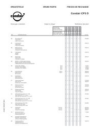
3.3 Steam generator construction<br />
1<br />
12<br />
2<br />
13<br />
26<br />
14<br />
25<br />
3<br />
4<br />
15<br />
5<br />
16<br />
6<br />
7<br />
17<br />
18<br />
19<br />
20<br />
24<br />
23<br />
22<br />
21<br />
8<br />
9<br />
10<br />
11<br />
The illustration above shows the large unit<br />
1 Housing (small, large)<br />
2 Cable openings, top side<br />
3 Main contactor<br />
4 Power board<br />
5 Control board with CP3 Card<br />
6 Display and control unit<br />
7 Remote operating and fault indication board<br />
8 Operation status indicators<br />
9 Cable openings, bottom side<br />
10 Drain key<br />
11 Unit switch<br />
12 Steam hose connector (option)<br />
13 Water cup<br />
14 Filling hose<br />
15 Water supply hose<br />
16 Inlet valve<br />
17 Overflow hose<br />
18 Drain connection (not visible)<br />
19 Water supply pipe<br />
20 Drain pump<br />
21 Type plate<br />
22 Data plate CP3 Card<br />
23 Steam cylinder<br />
24 Level sensor<br />
25 Auxiliary drain hose<br />
26 Electrode plug
11<br />
3.4 Functional description<br />
The Condair CP3 D is a pressureless steam generator that utilizes an electrode heating. The Condair<br />
CP3 D is designed for steam generation in a steam bath.<br />
Steam generation<br />
Any time steam is requested, the electrodes are supplied with voltage via main contactor. Simultaneously,<br />
the inlet valve opens and water enters the steam cylinder from the bottom via water cup<br />
and supply line. As soon as the electrodes come in contact with the water, current begins to flow<br />
between the electrodes, eventually heating and evaporating the water. The more the electrode surface<br />
is exposed to water, the higher is the current consumption and thus the steam capacity.<br />
Upon reaching the requested steam capacity, the inlet valve closes. If the steam generation decreases<br />
below a certain percentage of the required capacity, due to lowering of the water level (e.g.<br />
because of the evaporation process or drainage), the inlet valve opens until the required capacity is<br />
available again.<br />
If the required steam capacity is lower than the actual output, the inlet valve is closed until the desired<br />
capacity is achieved by lowering of the water level (evaporation process).<br />
Level monitoring<br />
A sensor provided in the steam cylinder cover detects when the water level gets too high. The moment<br />
the sensor comes in contact with water, the inlet valve closes.<br />
Drainage<br />
As a result of the evaporation process, the conductivity of the water increases due to an escalating<br />
mineral concentration. Eventually, an inadmissibly high current consumption would take place if this<br />
concentration process were permitted to continue. To prevent this concentration from reaching a<br />
value, unsuitably high for the operation, a certain amount of water is periodically drained from the<br />
cylinder and replaced by fresh water.<br />
Control<br />
The steam production is controlled steplessly (continuous control) by the KTY temperature sensor<br />
supplied (or an 0-10V temperature sensor) and the integrated continuous controller.<br />
Below a minimum controllable steam output a two-point control (On/Off) is used.
12<br />
3.5 System overview<br />
11<br />
12<br />
DS22<br />
DS60<br />
DS80<br />
1<br />
13<br />
2<br />
W22<br />
W30<br />
W45<br />
3<br />
4<br />
10<br />
Z261<br />
5<br />
9<br />
6<br />
125...1250 µS/cm<br />
1...10 bar<br />
1...40 °C<br />
8<br />
DS80<br />
7<br />
1 Steam generator<br />
2 Steam connection<br />
3 Water drain connection<br />
4 Water supply connection<br />
5 Filter valve (accessory “Z261”)<br />
6 Manometer (installation recommended)<br />
7 Funnel with siphon (building side)<br />
8 Water drain hose (accessory “DS80”)<br />
9 Control voltage supply<br />
10 Heating voltage supply<br />
11 Cable openings<br />
12 Steam hose (accessory “DS..”)<br />
13 Steam distributor (accessory “W..”)
13<br />
3.6 Options<br />
3.6.1 Options overview<br />
230V1 5...8<br />
Condair CP3 D<br />
400V3 5...8 9...15 16...45<br />
230V3 5...8 9...15 16...30<br />
D... Cleanable steam cylinder<br />
1x D3.. 1x D4.. 1x D6..<br />
Cleanable steam cylinder as an alternative to the<br />
disposable steam cylinder built in as standard (see<br />
also chapter 3.6.2).<br />
RFI Remote operating and fault indication<br />
1x RFI 1x RFI 1x RFI<br />
PCB with relay contacts for the connection of remote<br />
displays for “Operation”, “Steam”, “Fault” and<br />
“Service” as well as an analogue output for remote<br />
temperature indication and an analogue output for<br />
the temperature-dependent control of an optional<br />
flap control system.<br />
THV Terminals heating voltage<br />
1x M-THV 1x M-THV 1x L-THV<br />
Separate terminals for systems where direct connection<br />
of heating voltage to main contactor (standard version)<br />
is not permitted by local regulations.<br />
PG Cable gland 1x PG 1x PG 1x PG<br />
SC.. Steam hose connector 1x SC22 1x SC60 1x SC80<br />
MP Mounting profile 1x MP 1x MP 1x MP<br />
CVI Internal control voltage 1x M-CVI 1x M-CVI 1x L-CVI<br />
TRAFO Transformer (400V/230V) 1x M-Trafo 1x M-Trafo 1x L-Trafo
14<br />
3.6.2 Option details<br />
Steam cylinder<br />
The steam generator is available with two different types of steam cylinders:<br />
– Exchangeable steam cylinder type A... (standard version)<br />
– Cleanable steam cylinder type D... (option)<br />
The following tables present an overview of the steam cylinders used in the different models.<br />
Condair CP3 D...400V3 5...8 9...15 16...25 26...45<br />
For water conductivity from 125 to 1250 µS/cm<br />
Exchangeable steam cylinder 1xA363 1xA464 1xA674 1xA664<br />
Cleanable steam cylinder 1xD363 1xD464 1xD674 1xD664<br />
For low water conductivity<br />
Exchangeable steam cylinder 1xA343 1xA444 1xA654 1xA654<br />
Cleanable steam cylinder 1xD343 1xD444 1xD654 1xD654<br />
Condair CP3 D...230V3 5...8 9...15 16...21 22...30<br />
For water conductivity from 125 to 1250 µS/cm<br />
Exchangeable steam cylinder 1xA343 1xA444 1xA654 1xA644<br />
Cleanable steam cylinder 1xD343 1xD444 1xD654 1xD674<br />
Condair CP3 D...230V1 5...8<br />
For water conductivity from 125 to 1250 µS/cm<br />
Exchangeable steam cylinder<br />
Cleanable steam cylinder<br />
1xA342<br />
1xD342<br />
If you have questions regarding the steam cylinders please contact your Condair representative.
15<br />
3.7 Accessories<br />
Accessories for water installation<br />
Filter valve<br />
Condair CP3 D<br />
230V1 5...8<br />
400V3 5...8 9...15 16...45<br />
230V3 5...8 9...15 16...30<br />
1x Z261<br />
Accessories for steam installation<br />
Steam distributor<br />
(Details see chapter 5.4)<br />
230V1 5...8<br />
Condair CP3 D<br />
400V3 5...8 9...15 16...45<br />
230V3 5...8 9...15 16...30<br />
1x W22 1x W30 1x W45<br />
Steam hose / meter 1x DS22 1x DS60 1x DS80<br />
Condensate hose / meter<br />
Fragrance pump<br />
1x KS10<br />
1x SR25 230 VAC<br />
Accessories for operation control<br />
Temperature sensor<br />
Condair CP3 D<br />
230V1 5...8<br />
400V3 5...8 9...15 16...45<br />
230V3 5...8 9...15 16...30<br />
1x KTY
16<br />
3.8 Standard delivery<br />
The standard delivery includes:<br />
– Steam generator Condair CP3 D cpl. equipped with the options ordered according to chapter 3.6<br />
with KTY temperature sensor, water connection pipe G3/4" - 1/2", fixing set, Technical Documentation<br />
(this document) and spare parts list, packaged in cardboard box:<br />
– Unit small (WxHxD): 450 mm x 620 mm x 280 mm, shipping weight: 26 kg<br />
– Unit large (WxHxD): 559 mm x 667 mm x 350 mm, shipping weight: 31 kg<br />
– Ordered accessories with operating instructions according chapter 3.7, packed separately<br />
– Spare parts list<br />
3.9 Storing/Transportation/Packaging<br />
Storing<br />
Store the unit in a protected area meeting the following requirements:<br />
– Room temperature: 1 ... 40 °C<br />
– Room humidity: 10 ... 75 %rh<br />
Transportation<br />
For optimum protection always transport the unit in the original packaging.<br />
The weight of the small and the large unit is more than 20 kg (weight without packaging: small unit<br />
23 kg, large unit 28 kg). Therefore, always transport the unit with the help of another person or use<br />
a forklift or a crane. Always place the unit on its back side.<br />
Packaging<br />
Keep the original packaging of the Condair CP3 D for later use.<br />
In case you wish to dispose of the packaging, observe the local regulations on waste disposal. Never<br />
dispose of the packaging to the environment.
17<br />
4 Notes for the planning engineer<br />
4.1 Selecting the unit version<br />
To select the unit version the following planning steps are required:<br />
1. Calculating the required maximum steam capacity according chapter 4.1.1<br />
2. Selecting the unit version from the table in chapter 4.1.2<br />
4.1.1 Determination of the required steam capacity<br />
The steam capacity required for a particular steam bath can be determined with the following table:<br />
Cabin size<br />
Required steam capacity<br />
in m 3 Plastic cabin brick lined cabin<br />
4 5 kg/h 8 kg/h<br />
8 8 kg/h 12 kg/h<br />
12 10 kg/h 15 kg/h<br />
16 12 kg/h 18 kg/h<br />
20 13 kg/h 21 kg/h<br />
24 15 kg/h 24 kg/h<br />
28 17 kg/h 26 kg/h<br />
32 18 kg/h 29 kg/h<br />
36 20 kg/h 31 kg/h<br />
40 21 kg/h 34 kg/h<br />
44 23 kg/h 36 kg/h<br />
48 24 kg/h 38 kg/h<br />
52 26 kg/h 41 kg/h<br />
56 27 kg/h 43 kg/h<br />
60 29 kg/h 45 kg/h
18<br />
4.1.2 Selecting the unit<br />
Condair CP3 D 45 400V3<br />
Heating voltage *<br />
Max. steam capacity<br />
in kg/h<br />
Graduation<br />
in kg/h<br />
Model<br />
Condair CP3 D<br />
small<br />
Unit size<br />
large<br />
400V3<br />
(400V/3~/50...60Hz)<br />
230V3<br />
(230V/3~/50...60Hz)<br />
230V1<br />
(230V/1~/50...60Hz)<br />
5...15 1 5...15 1<br />
16...45 1 16...45 1<br />
5...15 1 5...15 1<br />
16...30 1 16...30 1<br />
5...8 1 5...8 1<br />
* Other heating voltages on request<br />
4.2 Selecting the options an accessories<br />
For selecting the options and accessories see chapters 3.6 and 3.7.
19<br />
5 Mounting and installation work<br />
5.1 Important notes for mounting and installation work<br />
Qualification of personnel<br />
All mounting and installation work must be carried out only by well qualified personnel authorised<br />
by the owner. It is the owner’s responsibility to verify proper qualification of the personnel.<br />
General note<br />
Strictly observe and comply with all information given in the present Technical Documentation regarding<br />
the location of the unit and the installation of water, steam and electricity.<br />
Observe and comply with all local regulations dealing with water, steam and electrical installations.<br />
Safety<br />
Some installation work requires removal of the unit cover. Please note the following:<br />
WARNING!<br />
CAUTION!<br />
Danger of electrical shock! You may get in touch with live parts when the unit<br />
is open. The steam generator must be connected to the mains only after all<br />
mounting and installation work has been completed and the cover has been<br />
relocated properly.<br />
The electronic components inside the steam generator are very sensitive to<br />
electrostatic discharge. When the unit is open for installation work, appropriate<br />
measures must be taken to protect these components against damage caused by<br />
electrostatic discharge (ESD protection).
20<br />
5.2 Installation overview<br />
Rmin. 300 mm<br />
Steam installation,<br />
see chapter 5.4<br />
min. 20 %<br />
+<br />
DS22<br />
DS60<br />
DS80<br />
min. 5 %<br />
–<br />
max. 4 m<br />
min. 300 mm<br />
60...70 °C<br />
Mounting the unit,<br />
see chapter 5.3<br />
Rmin. 300 mm<br />
W22<br />
W30<br />
W45<br />
ø40 mm<br />
G 1/2"<br />
1 ... 40 °C<br />
max. 75 %rh<br />
IP20<br />
400V/3~/50...60Hz<br />
230V/3~/50...60Hz<br />
230V/1~/50...60Hz<br />
125...1250 µS/cm<br />
1...10 bar<br />
1...40 °C<br />
G 1/2"<br />
ø10/8 mm<br />
Z261<br />
DS80<br />
min. 10 %<br />
–<br />
230V/1~/50...60Hz<br />
Electric installation,<br />
see chapter 5.6<br />
Water installation,<br />
see chapter 5.5<br />
≥ 40 mm
21<br />
5.3 Mounting the unit<br />
5.3.1 Notes on locating the unit<br />
min. 400 mm<br />
B<br />
min. 250 mm min. 400 mm<br />
60...70 °C<br />
T<br />
1 ... 40 °C<br />
max. 75 %rh<br />
IP20<br />
H<br />
min. 600 mm<br />
min. 600 mm<br />
Condair CP3 D ... 230V1 5...8<br />
Condair CP3 D ... 230V3 5...8 9...15 16...21 22...30<br />
Condair CP3 D ... 400V3 5...8 9...15 16...25 26...45<br />
Dimensions<br />
Housing (BxHxT) in mm 456x620x280 1 1<br />
559x667x350 1 1<br />
Weights<br />
Netweight in kg 21 21 21 28<br />
Operating weight in kg 26 32 32 65
22<br />
The installation site of the steam generator depends largely on the location of the steam distributor<br />
(see chapter 5.4). To ensure proper functioning of the steam generator and to obtain an optimal<br />
efficiency, the following points must be considered and observed when choosing the location for<br />
the steam generator:<br />
– Install the steam generator so that the length of the steam hose is kept as short as possible<br />
(max. 4 m) and that the minimum bend radius (R= 300 mm) and up-slope (20 %) or downslope<br />
(5 %) of the steam hose is observed (see chapter 5.4.5).<br />
– The steam generators Condair CP3 D are designed for wall-mounting. Make sure that the construction<br />
(wall, pillar, floor-mounted console, etc.) to which the steam generators are to be mounted,<br />
offers a sufficiently high load-bearing capacity (take notice of the weight information found in<br />
the dimension sand weights table above), and is suitable for the installation.<br />
– The back panel of the Condair CP3 D is retaining heat during operation (max. surface temperature<br />
of the metal housing approx. 60 - 70 °C). Make sure, therefore, that the construction (wall, pillar,<br />
etc.) to which the units are to be mounted, does not consist of heat-sensitive material.<br />
– Install the steam generator in such a manner that it is freely accessible with sufficient space<br />
available for maintenance purposes (refer to the above illustration for minimum distances).<br />
– The Condair CP3 D is protected according to IP20. Make sure the units are installed in a drip-proof<br />
location and the admissible ambient conditions are complied with.<br />
– The steam generator Condair CP3 D may only be installed in rooms with a floor drain.<br />
CAUTION!<br />
If for some reason the Condair CP3 D must be installed in a location without floor<br />
drain, it is mandatory to provide a leakage monitoring device to safely interrupt<br />
the water supply in case of leakage.<br />
– When fixing the Condair CP3 D use only the fixing materials supplied with the unit. If fixing<br />
with the materials supplied is not possible in your particular case, select a method of fixing that<br />
is of similar stability.
23<br />
5.3.2 Mounting the unit<br />
a<br />
A<br />
b<br />
Dimension<br />
Housing size<br />
small<br />
large<br />
a 228 mm 284 mm<br />
b 51 mm 51 mm<br />
c 500 mm 545 mm<br />
d 90 mm 144 mm<br />
e 180 mm 216 mm<br />
c<br />
B<br />
B<br />
d e<br />
Procedure<br />
1. Mark the attachment point “A” on the wall.<br />
2. Drill hole for attachment point “A” (diameter: 8 mm, depth: 40 mm).<br />
3. Insert the supplied plastic plug, and tighten the screw until the distance between the wall and<br />
the screw head is 4 mm.<br />
4. Unlock the two screws fixing the front panel to the unit, then remove the front panel.<br />
5. Hang up the unit onto the screw and adjust it horizontally and vertically using a spirit level. Then,<br />
mark the fixing points “B”.<br />
6. Drill the holes for the fixing points “B” (diameter: 8 mm, depth: 40 mm).<br />
7. Insert the supplied plastic plugs, and tighten the screws until the distance between the wall and<br />
the screw head is 4 mm.<br />
8. Hang the unit up onto the screws. Before tightening the screws, readjust the unit with the spirit<br />
level.<br />
9. Reattach the front panel and secure it with the two screws.
24<br />
5.3.3 Inspecting the installed unit<br />
Check the following points:<br />
Is the unit installed in the correct place (see chapter 5.3.1)<br />
Is the supporting surface stable enough<br />
Is the unit correctly aligned, vertically and horizontally<br />
Is the unit properly secured (see chapter 5.3.2)<br />
Has the front panel of the unit been relocated and correctly fixed with the two screws
25<br />
5.4 Steam installation<br />
5.4.1 Overview steam installation<br />
Rmin. 300 mm<br />
min. 20 %<br />
+<br />
DS22<br />
DS60<br />
DS80<br />
min. 5 %<br />
–<br />
max. 4 m<br />
min. 300 mm<br />
SC22<br />
SC60<br />
SC80<br />
Rmin. 300 mm<br />
W22<br />
W30<br />
W45<br />
5.4.2 Positioning/mounting the steam distributor<br />
It’s the responsibility of the customer to correctly position the steam distributor (e.g. W..) in the<br />
steam bath cabin.<br />
The steam distributor must be installed horizontally into the steam bath cabin.<br />
WARNING!<br />
Shield the steam outlet of the steam distributor with corresponding measures to<br />
make sure steam bath users can not be burned by the steamflow.<br />
W22/W30: ø43 mm<br />
W45: ø61 mm<br />
W22: ø22.5 mm<br />
W30: ø30 mm<br />
W45: ø45 mm
26<br />
5.4.3 Installing the steam hose<br />
Important! Use original Condair steam hose exclusively. Other types of steam hoses can cause<br />
undesired operational malfunctions.<br />
Instructions for the hose layout<br />
– Initially, the steam hose is led with an upslope of at least 20 % over a minimum height of<br />
300 mm above the top edge of the steam generator and then down to the steam distribution<br />
pipe with a minimum slope of 5 %.<br />
min. 20 %<br />
min. 5 %<br />
max. 4 m<br />
Rmin.<br />
300 mm<br />
min. 300 mm<br />
– The steam hose should be kept as short as possible (max. 4 m) while observing the minimum<br />
bend radius of 300 mm. Important! Allowance must be made for a pressure loss of 10 mm<br />
water column (approx. 100 Pa) per meter steam hose.<br />
Note: If your particular installation exceeds the maximum steam hose length of 4 m contact<br />
your Condair representative. In any case, steam hoses longer than 4 m must be insulated in<br />
their entire length.<br />
– Reductions in the cross section such as kinks should be avoided throughout the entire length of<br />
the hose. The installation of a stop cock in the steam hose is not permissible.<br />
– Steam hoses must be prevented from sagging (condensate pockets); if necessary, support with<br />
pipe clamps, trough, or wall brackets, or install a condensate drain in the steam hose.<br />
– Important! When deciding on the length and layout of the hose, it should be noted that the<br />
steam hose may become somewhat shorter with progressive ageing.<br />
Securing the hose<br />
The steam hose must be secured to the steam distribution pipe and the steam outlet of the steam<br />
generator by means of hose clamps.<br />
Caution! Do not overtighten the hose clamp on the steam connector of the steam generator.
27<br />
Steam line with fixed piping<br />
For steam lines with fixed piping, the same instructions apply to the laying of the piping as already<br />
described. The following additional notes should be observed:<br />
– The minimum internal diameter of 22 mm, 30 mm or 45 mm respectively should be applied<br />
over the whole length of the piping.<br />
– Use exclusively Cu pipe or stainless steel (min. DIN 1.4301).<br />
– To minimize the condensate formation (=loss), the steam pipes must be insulated.<br />
– The minimum bend radius for solid pipes is 4-5 x internal diameter.<br />
– Connection of the steam pipes to the steam distribution pipe and steam generator is effected by<br />
means of short lengths of steam hose secured with hose clamps.<br />
– Important! Allowance must be made for a pressure loss of 10 mm water column (approx.<br />
100 Pa) per meter length or per 90° bend.<br />
5.4.4 Inspecting the steam installation<br />
Use the following check list to ascertain that the steam installation was performed correctly:<br />
– Steam distribution pipe<br />
Steam distributor correctly positioned and secured (screws tightened)<br />
Steam outlet of the steam distributor with corresponding measures shielded to make sure<br />
steam bath users can not be burned by the steamflow.<br />
– Steam hose<br />
Maximum length of 4 m<br />
Minimum bend radius of 300 mm (4-5 x internal diameter with fixed piping)<br />
Have the instructions for hose positioning been followed<br />
Steam hose: no sagging (condensate pocket) or condensate drain with siphon (hose bend<br />
with a minimum diameter of 200 mm) installed at the lowest point<br />
Rigid steam lines: properly insulated Correct installation material used Minimum internal<br />
diameter maintained<br />
Steam hose(s) securely attached with clamps<br />
Heat expansion during operation and shortening of the hose with ageing taken into consideration
28<br />
5.5 Water installation<br />
5.5.1 Overview water installation<br />
ø40 mm<br />
G 1/2"<br />
G 1/2"<br />
ø10/8 mm<br />
DS80<br />
min. 50 cm<br />
min. 10 %<br />
–<br />
min. 10 %<br />
–<br />
125...1250 µS/cm<br />
1...10 bar<br />
1...40 °C<br />
Z261<br />
≥ 40 mm
29<br />
5.5.2 Notes on water installation<br />
Water supply<br />
The water supply is to be carried out according to the figure found in chapter 5.5.1 and the applicable<br />
local regulations for water installations. The indicated connection specifications must be observed.<br />
– The installation of the filter valve (accessory “Z261”, alternatively a shut-off valve and a 5 µm<br />
water filter can be used) should be made as close as possible to the steam generator.<br />
– Admissible mains pressure 1.0 to 10.0 bar (hammer-free system)<br />
For mains pressures >10 bar, the connection must be made via a pressure reducing valve (adjusted<br />
to 1.0 bar). For mains pressures
30<br />
5.5.3 Inspecting the water installation<br />
Check the following topics:<br />
– Water supply<br />
Has filter valve (accessory “Z261”) or shut-off valve and 5 µm water filter respectively been<br />
installed in supply line<br />
Have admissible water pressure (1 – 10 bar) and admissible temperature (1 – 40 °C) been<br />
observed<br />
Does the supply capacity match the steam generator and is the minimum inside diameter of<br />
the supply pipe maintained throughout the entire length<br />
Are all components and pipes properly secured and are all threaded connections securely<br />
tightened<br />
Is the water system properly sealed<br />
Does the water supply installation meet the requirements of the local regulations for water<br />
installations<br />
– Water drain<br />
Is the minimum inside diameter of the drain pipe of 40 mm maintained throughout the entire<br />
length<br />
Has drain pipe been installed with a downslope of at least 10 %<br />
Has the heat resistance of the material used been verified to be at least 100 °C<br />
Is the drain hose properly secured (hose clamps at unit connection tightened)<br />
Does the water drain installation meet the requirements of the local regulations for water<br />
installations
31<br />
5.6 Electric installation<br />
5.6.1 Wiring diagram Condair CP3 D<br />
A1<br />
DRIVER BOARD<br />
F2<br />
200mAF<br />
J2<br />
LINK UP<br />
X2 X7 X4 X3<br />
SWITCH VTX SUPPLY INLET V. DRAIN V. CONTACTOR<br />
LinkUp<br />
J4 Termination<br />
EXTERNAL CON.<br />
J1<br />
CPU BOARD<br />
JP3<br />
CONT.SIGN<br />
V+ INGND<br />
OUT 5V<br />
OUT 24V<br />
LIM. SIGN<br />
INGND<br />
JP1<br />
BLOWER<br />
V+ IN<br />
X6<br />
Modul B<br />
P N P1<br />
LEV. SENSOR<br />
X5<br />
F1 6.3 AT<br />
X1<br />
MAIN SUPPLY<br />
PE L1 N SC1 SC2<br />
SW1<br />
H1<br />
CPU BOARD<br />
CP3 Card<br />
Main unit<br />
J3<br />
DRIVER B<br />
J2<br />
FAULT REMOTE<br />
J<br />
+ –<br />
Heating<br />
J1 DRIVER A J4<br />
U1<br />
K1<br />
L1 L2 L3<br />
SW2<br />
X0<br />
H2<br />
STEAM BATH<br />
BOARD<br />
L1 L2 L3<br />
M2<br />
X2 X3 X4<br />
5 4 3 2 1 4 3 2 1 4 3 2 1<br />
AC LAMP FAN GND LIGHT ON 24V TEMP TEMP<br />
SW3<br />
S2<br />
Q3<br />
S1<br />
SENSOR<br />
SWITCH<br />
24V<br />
M1<br />
40 °C<br />
AIN<br />
U2<br />
F3<br />
L1 L2 L3 PE<br />
400 V/3~/50..60 Hz<br />
230 V/3~/50..60 Hz<br />
Q3<br />
F3<br />
AIN<br />
M3<br />
24V 0V<br />
H3<br />
L1 N PE<br />
230 V/1~/50..60 Hz<br />
Q4<br />
F4<br />
L1 N PE<br />
230 V/1N~/50..60 Hz<br />
S1 Temperature sensor (KTY)<br />
S2 Max. temperature switch 72 °C<br />
SW1 On/Off switch steam bath<br />
SW2 On/Off switch lightning steam bath<br />
SW3 Door switch steam bath (option)<br />
U1 Analogue output temperature 0-10V (=0-100°C)<br />
U2 Analogue output temperature signal for the control of the flap actuator M3<br />
X0 Connection terminal heating voltage<br />
X1 Connection terminal control voltage<br />
3<br />
2<br />
1<br />
SC1 SC2 N L1 N L1 PE PE N PUMP<br />
1 2 3 4 5 6 7 1 2 3<br />
X1 X5<br />
TEMP<br />
SWITCH<br />
F1 4AT F2 4AT<br />
FAN LAMP<br />
J2<br />
24V<br />
18V<br />
15V<br />
0V<br />
4 3 2 1<br />
GND<br />
24V<br />
PUMP<br />
REL2 REL1 LAMP<br />
J3 J1<br />
0V<br />
15V<br />
18V<br />
24V<br />
rt bl rs gu<br />
N<br />
L1<br />
Fault Remote Board<br />
H<br />
Analog Out<br />
4<br />
F1<br />
100mA<br />
3<br />
2<br />
1<br />
2<br />
1<br />
Steam Unit ON<br />
Service<br />
Error<br />
Sensor Supply<br />
Max. 60mA<br />
1 2 3 4 5 6 7 8 9 10<br />
H2 Control lamp lightning steam bath On/Off<br />
H3 Lightning steam bath (24VAC, max. 2x 25W)<br />
J Short circuited, if no door switch is connected<br />
K1 Main contactor (for connecting the heating voltage supply to the unit)<br />
M1 Fragrance pump (1x230VAC)<br />
M2 Fan steam bath cabin (24VAC, max. 50W)<br />
M3 Flap actuator (alternatively to the fan)<br />
Q3 External service switch heating voltage supply<br />
Q4 External service switch control voltage supply<br />
A1 Temperature sensor (0-10V)<br />
F1 Internal fuse “Driver board” (6.3 A, slow acting)<br />
F2 Internal fuse “Driver board” control signal (200 mA, fast acting)<br />
F1 Fuse fan “Steam bath board” (4 A, slow acting)<br />
F2 Fuse lightning “Steam bath board” (4 A, slow acting)<br />
F3 External fuse heating voltage supply<br />
F4 External fuse control voltage supply<br />
H Remote operating and fault indication<br />
H1 Control lamp steam bath On/Off
32<br />
5.6.2 Notes on electric installation<br />
– The electric installation must be carried out according to the wiring diagram in chapter 5.6.1 and<br />
the applicable local regulations. All information given in the wiring diagram must be followed and<br />
observed.<br />
– All cables must be lead into the unit via the cable openings equipped with cable glands (e.g. option<br />
“PG-cable gland”). The cable for the heating voltage supply must be lead into the unit from the<br />
bottom via the cable opening equipped with the clamp strap. Fix the cable with the clamp strap.<br />
– Make sure the cables do not scrub on any components.<br />
– Maximum cable length and required cross section per wire must be observed.<br />
– The supply voltages for heating and control must match the respective voltages stated in the<br />
wiring diagram.<br />
Heating voltage supply “Up”<br />
Caution! Before connecting, ensure that the mains voltage corresponds with the heating<br />
voltage for the unit (see mains code on the type label).<br />
The heating voltage supply is connected to the corresponding terminals of the main contactor according<br />
to the wiring diagram. In the supply line a service switch “Q1” (an all-pole disconnecting<br />
device with a minimum contact opening of 3 mm is an essential requirement) and a fuse group<br />
“F1” (essential requirement: fuses are to be as detailed in the following table) must be installed<br />
(by the client).<br />
Heating voltage<br />
400V3<br />
(400V/3~/50...60Hz)<br />
230V3<br />
(230V/3~/50...60Hz)<br />
230V1<br />
(230V/1~/50...60Hz)<br />
Max. steam<br />
capacity<br />
[kg/h]<br />
Model<br />
Condair CP3 D<br />
Nominal<br />
power<br />
[kW]<br />
Nominal<br />
current<br />
[A]<br />
Main<br />
fuses F3<br />
[A]<br />
5...8 5...8 6.0 8.7 3x 10<br />
9...12 9...12 9.0 13.0 3x 16<br />
13...15 13...15 11.3 16.3 3x 20<br />
16...20 16...20 15.0 21.7 3x 25<br />
21...25 21...25 18.8 27.1 3x 35<br />
26...30 26...30 22.5 32.5 3x 40<br />
31...42 31...42 31.5 45.5 3x 50<br />
43...45 43...45 33.8 48.8 3x 63<br />
5...8 5...8 6.0 15.8 3x 20<br />
9...15 9...15 11.3 29.6 3x 40<br />
16...21 16...21 15.8 41.4 3x 50<br />
22...30 22...30 22.5 59.1 3x 63<br />
5 5 3.8 16.3 20<br />
6...8 6...8 6.0 26.1 35<br />
Note: The minimum cross section of the supply cable must comply with the local regulations.<br />
Control voltage supply “Uc”<br />
Caution! Before connecting, make sure that the mains voltage corresponds with the control<br />
voltage of the unit (220…240 V, 50…60 Hz).<br />
The control voltage supply is connected to the terminals L1 and N according to the wiring diagram.<br />
In the supply line a service switch “Q2” (an all-pole disconnecting device with a minimum<br />
contact opening of 3 mm is an essential requirement) and a fuse “F2” (max. 10 A, slow acting,<br />
essential requirement) must be installed (by the client).<br />
Note: The minimum cross section of the supply cable must comply with the local regulations.
33<br />
Remote indicator board H<br />
The remote operating and fault indicators must be connected to the respective potential-free relay<br />
contacts of the remote indicator board according to the wiring diagram:<br />
– “Error”: This relay is activated if a fatal error occurs.<br />
– “Maintenance”: This relay is activated after the maintenance interval time has expired.<br />
– “Steam”: This relay is activated as soon as the CP3 D produces steam.<br />
– “Unit on”: This relay is activated as soon as the CP3 D is switched on.<br />
Caution! The maximum contact load is: 250V/1A.<br />
Caution! Appropriate suppressor modules are to be used for the switching of relays and<br />
miniature contactors.<br />
Remote temp. indication U1:<br />
Temperature signal U2:<br />
Temperature signal 0...10V (0...100%) for remote temp. indication<br />
Temperature signal for the control of the flap actuator<br />
Fragrance pump M1 (230VAC)<br />
The fragrance pump is connected to terminals X5-1, X5-2 and X5-3 on the steam bath board according<br />
to the wiring diagram.<br />
Note: The cross-section of the cable must comply with the applicable local regulations.<br />
Steam bath lighting H3 (24VAC, max. 2x 25 W)<br />
The steam bath lighting is connected to terminals X2-3 and X2-4 on the steam bath board according<br />
to the wiring diagram<br />
Note: The cross-section of the cable must comply with the applicable local regulations.<br />
Steam bath fan M2 (24VAC, max. 50 W)<br />
The steam bath fan is connected to terminals X2-1 and X2-2 on the steam bath board according<br />
to the wiring diagram.<br />
Note: The cross-section of the cable must comply with the applicable local regulations.<br />
Flap actuator M3 (24 VAC, max. 50 W), alternatively to the steam bath fan M2<br />
The flap actuator is connected to terminals X2-1 and X2-5 on the steam bath board according to<br />
the wiring diagram. The control signal to control the flap motor is always active.<br />
Note: The cross-section of the cable must comply with the applicable local regulations.<br />
Temperature sensor KTY S1<br />
The supplied temperature sensor KTY is connected to terminals X4-1 and X4-2 according to the<br />
wiring diagram. The steam bath board is ready for the connection of the supplied temperature sensor,<br />
hence not further adjustments are required.<br />
The temperature sensor must be installed in a appropriate location inside the steam bath (away<br />
from the steam exit).<br />
Please refer the separate installation instructions for proper location and connection of the temperature<br />
sensor.
34<br />
5.6.3 Inserting the CP3 Card<br />
All important operating parameters such as the maximum steam capacity, the heating voltage, the<br />
number of base units as well as the differentiation between main and extension unit are permanently<br />
stored on the CP3 Card.<br />
Before you start the electrical installation, check whether the CP3 Card is installed. If it is not, check<br />
whether the type designation on the CP3 Card supplied corresponds with the type designation<br />
on the data plate of the unit (the data plate is located inside the unit). If the designations<br />
match, place the CP3 Card in the card holder on control print . Then cover the data plate inside the<br />
unit beside the type plate with the data plate supplied (self-adhesive).<br />
If the type designation on the CP3 Card and the data plate do not match, the CP3 Card must not be<br />
installed. If this is the case, contact your Condair supplier.<br />
5.6.4 Inspecting the electrical installation<br />
Check the following points:<br />
Do the supply voltages for heating and control comply with the relevant voltages given in the<br />
wiring diagram<br />
Is the correct CP3 Card inserted<br />
Are the voltage supplies (heating and control voltage) correctly fused<br />
Is the service switch “Q..” installed in the supply line for to the heating and control voltage<br />
Are all components correctly connected according to the wiring diagram<br />
Are all connecting cables fastened<br />
Are the connecting cables free of tension (passed through cable glands)<br />
Does the electric installation meet the applicable local regulations for electric installations<br />
Is the front panel mounted and correctly fixed with the two screws
35<br />
6 Operation<br />
6.1 Commissioning<br />
Proceed as follows when putting the unit into operation:<br />
1. Examine the steam generator and installation for possible damage.<br />
Damaged devices or devices with damaged installation may present danger to<br />
human life or cause severe damage to material assets.<br />
Damaged units and/or units with damaged or faulty installation must not<br />
WARNING!<br />
be operated.<br />
2. Check whether the front panel is mounted and fixed with the two screws.<br />
3. Open the filter valve (or the shut-off valve, respectively) in the water supply line.<br />
4. Switch on the service switches for mains supplies (heating and control voltage).<br />
5. Actuate the unit switch of the steam generator. Switch lights up.<br />
CP3 STEAMBATH<br />
STARTUP:<br />
INIT MODULE<br />
XXXXXXXXXXXXXXXXXXXX<br />
Menu<br />
Set<br />
CP3 D45 400V3<br />
Steam Bath :Standby<br />
Temperature :34°C<br />
Setpoint :48°C<br />
05.05.2008 12.00.00<br />
Start Light<br />
Menu<br />
The steam generator carries out a system test, during which all the<br />
LEDs light up and the opposite display is shown.<br />
If a failure occurs on the system test, a corresponding error message<br />
is shown in the display.<br />
After the system test the operating display is shown.<br />
Note: The contents of the operating display and the setting of the keys<br />
depend on the actual operating status and on the configuration of the<br />
Condair CP3 D and can differ from the opposite display.<br />
CP3 D45 400V3<br />
Steam Bath :Heating<br />
Temperature :34°C<br />
Setpoint :48°C<br />
05.05.2008 12.00.00<br />
Stop Light<br />
Menu<br />
Depending on the selected operating mode of the Condair CP3 D,<br />
the steam generator must manually be started via the Start/Stop<br />
button of the display and control unit or via an external Start/Stop<br />
button or the operation runs time-controlled via the day timer or the<br />
week timer. As soon as the steam generator is started, the heating<br />
current is switched on. The inlet valve opens (slight delay) and the<br />
steam cylinder fills with water. As soon as the submerged electrodes<br />
heat the water up the green LED lights up and after a few minutes<br />
(approx. 5–10 minutes, depending on the conductivity of the water)<br />
steam is produced and the steam bath cabin is heated up. As soon<br />
as the set temperature in the steam bath cabin is achieved, the light<br />
is switched on and the bath phase starts. During the bath phase the<br />
fragrance pump (if available) is controlled in accordance with the selected<br />
operating mode and the fan (or the flap actuator) is controlled<br />
in accordance with the set temperature and the actual temperature<br />
in the steam bath cabin.<br />
Note: If the Condair CP3 D is operated with water of low conductivity it may happen that the<br />
maximum steam capacity is not reached in the first few hours of operation. This is normal. As<br />
soon as the conductivity has reached a sufficient level (due to the vaporisation process) the steam<br />
generator will reach the maximum steam capacity.
36<br />
6.2 Notes on operation<br />
6.2.1 Function of the display and operating elements<br />
Display and control unit<br />
Function: Configuration of the Condair CP3 D.<br />
Indication of operating parameters.<br />
Reset of maintenance counter and error indication.<br />
red LED “Error”<br />
Function: The LED lights in case of a malfunction of the unit. The<br />
type of malfunction is shown in the display, see chapter<br />
8).<br />
The LED flashes alternately with the green LED if the<br />
maximum temperature switch has triggered.<br />
yellow LED “Warning”<br />
Function: The LED lights if the cylinder maintenance is due.<br />
green LED “Steam”<br />
Function: The LED lights if the unit produces steam.<br />
The LED flashes alternately with the red LED if the<br />
maximum temperature switch has triggered.<br />
Drain key<br />
Function:<br />
Manual draining of the steam cylinder. After having<br />
pressed the drain key, the draining is controlled via<br />
the display and control unit.<br />
Unit switch<br />
Function:<br />
Switches the unit on and off. The switch is illuminated<br />
when the unit is running.<br />
6.2.2 Remote operating and fault indication<br />
Via the operating and fault indication the following operating status are shown remotely:<br />
Activated remote<br />
indication relay<br />
When<br />
Display on unit<br />
H1 “Error”<br />
H2 “Service”<br />
H3 “Steam demand”<br />
A malfunction is present, further<br />
operation is not possible, the heating<br />
voltage is interrupted<br />
Steam cylinder maintenance is due.<br />
The unit remains operational for a<br />
certain time<br />
Steam demand/<br />
Steam production<br />
Red LED lights<br />
An error message is shown in the<br />
display<br />
Yellow LED lights<br />
The service warning message is<br />
shown in the display<br />
Green LED lights<br />
The standard operating display is<br />
shown.<br />
H4 “Unit on” Unit ready for operation Unit switch lights<br />
The standard operating display is<br />
shown.
37<br />
6.2.3 Inspections during operation<br />
During operation the Condair CP3 D and the humidification system have to be inspected weekly. On<br />
this occasion check the following:<br />
• the water and steam installation for any leakage.<br />
• the steam generator and the other system components for correct fixing and any damage.<br />
• the electric installation for any damage.<br />
If the inspection reveals any irregularities (e.g. leakage, error indication) or any damaged components<br />
take the Condair CP3 D out of operation as described in chapter 6.3. Then, contact your Condair<br />
representative.<br />
6.2.4 Carrying out manual draining<br />
Proceed as follows to drain the unit manually:<br />
Manual Drain<br />
Press START or STOP<br />
Modul A<br />
Esc Start<br />
Set<br />
1. Briefly press the drain key. The drain dialogue appears in the<br />
display.<br />
2. Press the key. The heating voltage is interrupted and the<br />
drain pump starts. The yellow LED flashes.<br />
To stop the drain cycle press the key.<br />
Note: By pressing the key the unit returns to the indication<br />
level. A drain cycle in progress will be stopped automatically.<br />
6.3 Taking the unit out of operation<br />
In order to take the steam generator out of operation, perform the following steps:<br />
1. If the unit has to be switched off because of a malfunction, please note the error code of the<br />
actual error message shown in the display.<br />
2. Close the shut-off valve in the water supply line<br />
3. Start manual draining (see chapter 6.2.4) and wait until the steam cylinder is empty.<br />
4. Actuate the unit switch<br />
5. Disconnect steam generator from the mains: Switch off all service switches to mains supplies<br />
(heating and control voltage) and secure switches in “off” position against accidentally being<br />
switched on, or clearly mark the switches.<br />
WARNING!<br />
If steam was produced just before the unit is taken out of operation, wait before<br />
opening the unit and let the steam cylinder cool down to prevent danger<br />
of burning.
38<br />
6.4 Overview and operating of the menu<br />
Operating<br />
CP3 D45 400V3<br />
Steam Bath :Standby<br />
Temperature :34°C<br />
Setpoint :48°C<br />
05.05.2008 12.00.00<br />
Start Light<br />
Menu<br />
The operating and display unit is operated via the four keys located<br />
just below the display. The 4 status fields at the bottom of the display<br />
show the active keys the functions assigned to them.<br />
actual key setting<br />
keys<br />
Menu overview<br />
Operating display<br />
CP3 D45 400V3<br />
Steam Bath :Standby<br />
Temperature :34°C<br />
Setpoint :48°C<br />
05.05.2008 12.00.00<br />
Start Light Menu<br />
Menu level<br />
Main Menu<br />
Setpoint<br />
Mode<br />
Aroma<br />
Info<br />
User<br />
Esc<br />
:48°C<br />
:Manual<br />
:Set<br />
:Set<br />
:Set<br />
Set<br />
Setting the setpoint temperature<br />
Main Menu<br />
Setpoint<br />
Mode<br />
Aroma<br />
Info<br />
User<br />
Esc<br />
:48°C<br />
:Manual<br />
:Set<br />
:Set<br />
:Set<br />
Set<br />
Setting the control mode<br />
Main Menu<br />
Setpoint<br />
Mode<br />
Aroma<br />
Info<br />
User<br />
Esc<br />
:48°C<br />
:Manual<br />
:Set<br />
:Set<br />
:Set<br />
Set<br />
Fragrance pump settings<br />
Main Menu<br />
Setpoint<br />
Mode<br />
Aroma<br />
Info<br />
User<br />
Esc<br />
:48°C<br />
:Manual<br />
:Set<br />
:Set<br />
:Set<br />
Set<br />
Info<br />
Unit Status :Set<br />
ErrorHistory:Set<br />
Esc<br />
Set<br />
Menu Info<br />
– Interrogation of unit information<br />
– Interrogation of the malfunction list<br />
Main Menu<br />
Setpoint<br />
Mode<br />
Aroma<br />
Info<br />
User<br />
Esc<br />
:48°C<br />
:Manual<br />
:Set<br />
:Set<br />
:Set<br />
Set<br />
User Code<br />
8808<br />
Enter Number<br />
Confirm with Set<br />
Esc<br />
Set<br />
User<br />
Maintenance :Set<br />
Settings<br />
:Set<br />
Modbus<br />
:Set<br />
Esc<br />
Set<br />
Menu User<br />
– Resetting the maintenance counter<br />
– Unit settings<br />
– Modbus settings
39<br />
6.5 Interrogation functions<br />
6.5.1 Information in the operating display<br />
The following information are shown in the operating display:<br />
CP3 D45 400V3<br />
Steam Bath :Standby<br />
Temperature :34°C<br />
Setpoint :48°C<br />
05.05.2008 12.00.00<br />
Start<br />
Light<br />
Menu<br />
Operating status of the steam generator (Standby, Heating or Drying)<br />
Actual temperature in the steam bath cabin<br />
Set nominal steam bath temperature<br />
Date (dd.mm.yyyy) and time (hh.mm.ss)<br />
6.5.2 Interrogation of unit information<br />
Unit Status<br />
Cylinder type<br />
1<br />
A664<br />
Cylinder Operat.Hourd2<br />
A 0h<br />
11.11.2006 12.00.00<br />
Esc<br />
Set<br />
Software Version 3<br />
1.01LA00 12.00.00<br />
Operation<br />
4<br />
Intern<br />
∑ Steam<br />
5<br />
0kg/h12.00.00<br />
Actual Request<br />
6<br />
A 0%<br />
Actual Temperature 7<br />
42°C<br />
Average Drain Time 8<br />
A 0.0 s<br />
Max. Level Sensor 9<br />
A Off<br />
Max. Level Counter 10<br />
A 0<br />
Max. Temp.Fuse<br />
11<br />
Off<br />
Door Switch<br />
12<br />
Open<br />
System Operation Hour13<br />
0h<br />
Select the list with the unit information:<br />
Path: Main menu > Info > Unit Status<br />
Press < > and < > keys, in order to select the unit information available<br />
in the list:<br />
1 Type designation of the steam cylinder type<br />
2 Total operating hours of the steam cylinder<br />
3 Software version (1.00)/language version (LA00)<br />
4 Operating mode of the steam generator<br />
5 Actual steam capacity of the unit in kg/h<br />
6 Actual request in %<br />
7 Actual temperature in the steam bath in °C<br />
8 Calculated mean drain time of the unit in seconds<br />
9 Actual status of the maximum level sensor in the steam cylinder<br />
10 Counter showing the number of times the maximum level in the<br />
steam cylinder has been exceeded<br />
11 Actual status of the maximum temperature switch<br />
12 Actual status of the door switch of the steam bath cabin<br />
13 Total operating hours since the initial commissioning<br />
Press the key several times to quit the unit information list and to<br />
return to the standard operating display.
40<br />
6.5.3 Interrogation of the malfunction list<br />
The error messages generated by the last 20 malfunctions that occurred are saved in the malfunction<br />
list of the Condair CP3 D and can be interrogated.<br />
ErrorHistory<br />
01/05 11.11.06 12.34<br />
E32A Temp.Sensor void<br />
No sensor signal<br />
Temp.Sensor damaged<br />
11.11.2006 12.00.00<br />
Esc<br />
Set<br />
Select the error history list:<br />
Path: Main menu > Info > ErrorHistory<br />
The last error that occurred is shown with:<br />
– running number of the error<br />
– date and time of occurrence (version Pro only)<br />
– error code (Warning: W..., Error: E...<br />
– error message<br />
– additional info text regarding the error<br />
Press < > and < > keys, in order to select further error messages in<br />
the list.<br />
Press the key several times to quit the error history list and to<br />
return to the standard operating display.<br />
6.6 Unit settings<br />
6.6.1 Setting the setpoint temperature<br />
Main Menu<br />
Setpoint<br />
Mode<br />
Aroma<br />
Info<br />
User<br />
Esc<br />
:48°C<br />
:Manual<br />
:Set<br />
:Set<br />
:Set<br />
Set<br />
Select “Setpoint” in the main menu, then press the key.<br />
In the upcoming modification dialogue set the desired nominal temperature<br />
for the steam bath.<br />
Factory setting: 48 °C<br />
Setting range: 25 °C ... 55 °C<br />
6.6.2 Setting the control mode<br />
Note: This setting is available only if the setting “Operation” in the steam bath settings (see chapter<br />
6.6.4.3) is set to “Intern”.<br />
Main Menu<br />
Setpoint<br />
Mode<br />
Aroma<br />
Info<br />
User<br />
Esc<br />
:48°C<br />
:Manual<br />
:Set<br />
:Set<br />
:Set<br />
Set<br />
Select “Mode” in the main menu, then press the key.<br />
In the upcoming modification dialogue set the desired control mode.<br />
Factory setting: Manual<br />
Options:<br />
Manual, Timer
41<br />
Description of the control mode settings<br />
– Manual: The steam generator must be switched on and off via the Start/Stop key<br />
in the operating display.<br />
CP3 D45 400V3<br />
Steam Bath :Standby<br />
Temperature :34°C<br />
Setpoint :48°C<br />
05.05.2008 12.00.00<br />
Start Light<br />
Menu<br />
CP3 D45 400V3<br />
Steam Bath :Heating<br />
Temperature :37°C<br />
Setpoint :48°C<br />
05.05.2008 12.05.00<br />
Stop Light<br />
Menu<br />
– Timer: The steam generator is switched on and off time controlled via the day<br />
timer. The timer settings can be accessed by pressing the key in<br />
the operating display.<br />
CP3 D45 400V3<br />
Steam Bath :Standby<br />
Temperature :34°C<br />
Setpoint :48°C<br />
05.05.2008 12.00.00<br />
Timer<br />
Light<br />
Menu<br />
Timer<br />
Status :Off<br />
Start time :18:00<br />
Duration :15min<br />
Esc<br />
Set<br />
– Status: activate (On) or deactivate (Off) timer function<br />
– Start time: set starting time (format: hh:mm)<br />
– Duration: Set heating time in minutes<br />
6.6.3 Setting the fragrance pump settings<br />
Aroma<br />
Pump<br />
:On<br />
Interval :5min<br />
Impulse :3s<br />
Esc<br />
Set<br />
Select “Aroma” in the main menu, then press the key. The<br />
fragrance pump settings appear. Press the < > and < > keys in order<br />
to select the individual settings and press the key to call up the<br />
modification dialogue for the selected setting.<br />
Description of the fragrance pump settings<br />
– Pump: Activating and deactivating the fragrance pump.<br />
Factory setting: On<br />
Options:<br />
On (Pump activated)<br />
Off (Pump deactivated)<br />
– Interval: Setting the interval time in minutes for the pump impulses.<br />
Factory setting: 5 min<br />
Setting range: 2 ... 20 min<br />
– Impulse: Setting the duration for a pump impulse in seconds.<br />
Factory setting: 3 s<br />
Setting range: 2 ... 10 s
42<br />
6.6.4 Unit settings in the settings menu<br />
6.6.4.1 Launching the settings menu<br />
Settings<br />
Language :English<br />
BathSetting :Set<br />
Date :05.05.08<br />
Time :12:00<br />
Cylinder :Set<br />
Esc<br />
Set<br />
Power Limit :Set<br />
GFCI-Mode :Aus<br />
Water Manag.:Set<br />
Remote Test :Set<br />
Bath Test :Set<br />
Contrast :15<br />
Select the settings menu:<br />
Path: Main menu > User > Password entry: 8808 > Settings<br />
Press the < > and < > keys in order to select the individual settings in<br />
the settings menu.<br />
Detailed information on the different settings are found in the following<br />
chapters.<br />
6.6.4.2 Selecting the dialogue language<br />
Settings<br />
Language :English<br />
BathSetting :Set<br />
Date :05.05.08<br />
Time :12:00<br />
Cylinder :Set<br />
Esc<br />
Set<br />
Select “Language” in the settings menu, then press the key.<br />
In the upcoming modification dialogue select the desired dialogue language.<br />
After confirmation, the unit automatically switches to the selected<br />
dialogue language.<br />
Factory setting: country specific<br />
Options:<br />
divers languages<br />
6.6.4.3 Steam bath control settings<br />
Settings<br />
Language :English<br />
BathSetting :Set<br />
Date :05.05.08<br />
Time :12:00<br />
Cylinder :Set<br />
Esc<br />
Set<br />
BathSetting<br />
Operation :WeekTime<br />
Week Timer :Set<br />
Fan<br />
:Set<br />
Temp.Sensor :Set<br />
Temp.Control:Int(PI)<br />
Esc<br />
Set<br />
P-Band :4°C<br />
Integr.-Time:2min<br />
Max.Heating :2h<br />
Max.DoorOpen:2min<br />
Select “BathSetting” in the settings menu, then press the key.<br />
The steam bath control settings appear. Press the < > and < > keys in<br />
order to select the individual settings and press the key to call up<br />
the modification dialogue for the selected setting.<br />
Note: The settings available depend on the current settings of the individual<br />
parameters. The opposite display shows the maximum number<br />
of settings available.<br />
Description of the steam bath control settings<br />
– Operation: Setting the operating mode.<br />
Factory setting: Intern<br />
Options:<br />
Intern (switching the unit on and off the Start/<br />
Stop key of the display and control unit or via the<br />
day timer, see chapter 6.6.2 “ Setting the control<br />
mode”)<br />
Extern (switching the unit on and off via an external<br />
On/Off switch)<br />
WeekTime (the operation of the unit is time controlled<br />
via the week timer, see following settings<br />
“WeekTimer”)
43<br />
– Wochen Timer: With the settings in the submenu “Week Timer” you can configure the<br />
week timer for the time controlled operation of the steam generator.<br />
Note: This menu item is available only if the operating mode (see previous<br />
menu item “Operation”) is set to “WeekTime”.<br />
– Week timer deactivated:<br />
Week Timer<br />
Timer :Off<br />
Event 1 :18:00<br />
Event 2 :19:00<br />
Event 3 :--:--<br />
Event 4 :--:--<br />
Esc<br />
Set<br />
– Week timer activated:<br />
Week Timer<br />
Timer :On<br />
Event 1 :18:00<br />
Event 2 :19:00<br />
Event 3 :--:--<br />
Event 4 :--:--<br />
Esc<br />
Set<br />
Event 1<br />
Weekday :Mo-Fr<br />
Time :18:00<br />
Steam Bath :On<br />
Esc<br />
Set<br />
If the timer is activated, up to eight switching<br />
points (events 1 - 8) can be defined to switch<br />
the steam generator On or Off.<br />
Each switching point is defined by a weekday<br />
or weekday range, the switching point and<br />
the desired operating status of the steam<br />
generator.<br />
Configuration notes:<br />
– the settings of an event remain active up to the next event.<br />
– the software does not check the plausibility of the timer settings.<br />
Therefore, make sure your settings make sense.<br />
– Fan: With the settings in the submenu “Fan” you can determine the operating<br />
mode of the fan as well as the post-operational time of the fan for drying<br />
the steam bath cabin.<br />
Fan<br />
Mode<br />
:3 Stages<br />
Drying Time :20min<br />
Esc<br />
Set<br />
– Mode: Setting the operating mode of the fan.<br />
Factory setting:<br />
Options:<br />
3 Stages<br />
3 Stages (Operation of the fan with three<br />
performance levels 15/18/24VAC, which are<br />
controlled in dependency of the temperature<br />
in the steam bath cabin)<br />
1 Stage (Operation of the fan with only one<br />
performance level 24VAC)<br />
Off (Fan off)<br />
– Drying time: Setting the post-operational time of the fan for<br />
drying the steam bath cabin.<br />
Factory setting:<br />
Setting range:<br />
20 min<br />
1 ... 60 min
44<br />
– Temp.Sensor: With the settings in the submenu “Temp.Sensor” you can determine the<br />
signal source as well as the type and the signal sizes of the used sensor.<br />
Temp.Sensor<br />
SignalSource:Modbus<br />
Temp.Sensor<br />
Signalsource:Analog<br />
Type<br />
:KTY<br />
Nom. Value :2020<br />
Temp.Sensor<br />
SignalSource:Analog<br />
Type<br />
:0-10V<br />
0V-Temp. :0°C<br />
10V-Temp. :100°C<br />
Esc<br />
Set<br />
Esc<br />
Set<br />
Esc<br />
Set<br />
– SignalSource: Setting the signal source.<br />
Factory setting:<br />
Options:<br />
Analog<br />
Analog, Modbus<br />
– Type: Setting the type of the sensor in use (this menu<br />
item is available only if signal source is set to<br />
“Analog”).<br />
Factory setting:<br />
Options:<br />
KTY<br />
KTY (included in the delivery), 0...10V<br />
– Nom. Value: Set the nominal value of the KTY sensor in Ohm.<br />
Note: this setting is available only if sensor type “KTY” is selected.<br />
Factory setting: 2020<br />
Setting range: 1900...2100<br />
– 0V-Temp.: Setting the temperature value in °C which equals<br />
to 0 V for a 0-10V temperature sensor.<br />
Note: this setting is available only if sensor type “0-10V” is selected.<br />
Factory setting: 0°C<br />
Setting range: -50 ... +20°C<br />
– 100V-Temp.: Setting the temperature value in °C which equals<br />
to 10 V for a 0-10V temperature sensor.<br />
Note: this setting is available only if sensor type “0-10V” is selected<br />
Factory setting: 100°C<br />
Setting range: +80 ... +200 °C<br />
– Temp.Control: Setting the type of temperature control.<br />
Factory setting: Int.(P)<br />
Options:<br />
Int. (P) (Internal P controller)<br />
Int. (PI) (Internal PI controller)<br />
– P-Band: Setting the proportional range in °C for the internal P/PI controller.<br />
Note: This setting is available only if the internal P or PI controller is activated.<br />
Factory setting: 4°C<br />
Setting range: 1...60°C<br />
– Integr.-Time: Setting the integral time in minutes for the internal PI controller.<br />
Note: This setting is available only if the internal PI controller is activated.<br />
Factory setting: 2 minutes<br />
Setting range: 1...60 minutes
45<br />
– Max.Heating: Setting the maximum heating time for the steam generator. As soon as<br />
the maximum heating time is reached, the steam production is interrupted<br />
and the drying phase begins (if the fan is activated). After the drying phase<br />
the light is switched off automatically.<br />
Factory setting: 2 h<br />
Setting range: 1 ... 24 h<br />
– Max.Door Open: Setting the maximum time the door of the steam bath cabin can be open,<br />
before the steam production is interrupted.<br />
Factory setting: 2 min<br />
Setting range: 1 ... 30 min<br />
6.6.4.4 Setting the date<br />
Settings<br />
Language :English<br />
BathSetting :Set<br />
Date :05.05.08<br />
Time :12:00<br />
Cylinder :Set<br />
Esc<br />
Set<br />
Select “Date” in the settings menu, then press the key. In the upcoming<br />
modification dialogue set the actual date (format: “dd.mm.yy”).<br />
6.6.4.5 Setting the time<br />
Settings<br />
BathSetting :Set<br />
Date :05.05.08<br />
Time :12:00<br />
Cylinder :Set<br />
Power Limit :100%<br />
Esc<br />
Set<br />
Select “Time” in the settings menu, then press the key. In the<br />
upcoming modification dialogue set the actual time (format: “hh.mm”).<br />
6.6.4.6 Cylinder settings<br />
Settings<br />
Date :05.05.08<br />
Time :12:00<br />
Cylinder :Set<br />
Power Limit :100%<br />
GFCI-Mode :Aus<br />
Esc<br />
Set<br />
Cylinder<br />
Cyl. Line :Dispos<br />
Cyl. Number :644<br />
Select “Cylinder” in the settings menu, then press the key.<br />
The cylinder settings appear. Press the < > and < > keys in order to<br />
select the individual settings and press the key to call up the<br />
modification dialogue for the selected setting.<br />
Esc<br />
Set<br />
Description of the cylinder settings<br />
– Cyl. Line: Selecting the cylinder type.<br />
Factory setting: Dispos<br />
Options:<br />
Dispos (Disposable cylinder A..)<br />
Clean (Cleanable cylinder D..)<br />
– Cyl. Number: Selecting the cylinder number<br />
Factory setting: according the installed cylinder<br />
Options: 342, 343, 363, 444, 464, 654, 644, 664, 674
46<br />
6.6.4.7 Setting the capacity limitation<br />
Settings<br />
Teit :12:00<br />
Cylinder :Set<br />
Power Limit :100%<br />
GFCI-Mode :Aus<br />
Water Manag.:Set<br />
Esc<br />
Set<br />
Select “Power Limit” in the settings menu, then press the key.<br />
In the upcoming modification dialogue set the desired power limit in %<br />
of the maximum capacity.<br />
6.6.4.8 Activating/Deactivating fault current relay operation<br />
Settings<br />
Cylinder :Set<br />
Power Limit :100%<br />
GFCI-Mode :Aus<br />
Water Manag.:Set<br />
Remote Test :Set<br />
Esc<br />
Set<br />
Select “GFCI-Mode” in the settings menu, then press the key.<br />
In the upcoming modification dialogue select whether or not the Condair<br />
CP3 D is connected to a fault current relay protected mains supply.<br />
Factory setting: Off<br />
Options:<br />
On (mains supply with fault current relay protection)<br />
Off (mains supply without fault current relay<br />
protection)<br />
6.6.4.9 Water management settings<br />
Settings<br />
Power Limit :100%<br />
GFCI-Mode :Aus<br />
Water Manag.:Set<br />
Remote Test :Set<br />
Bath Test :Set<br />
Esc<br />
Set<br />
Water Manag.<br />
Conductivity:>125µS<br />
Drain Factor:1.0<br />
StandbyDrain:Full<br />
StandbyDelay:72h<br />
Force Drain :On<br />
Esc<br />
Set<br />
Select “Water Manag.” in the settings menu, then press the <br />
key.<br />
The water management settings menu appears.<br />
Press the < > and < > keys in order to select the individual settings and<br />
press the key to call up the modification dialogue for the selected<br />
setting.<br />
Force Delay :72h<br />
Description of the water management settings<br />
– Conductivity: Selecting the conductivity range of the supply water.<br />
Factory setting: >125 μS/cm<br />
Options:<br />
>125 μS/cm,
47<br />
– StandbyDelay: Setting the period of time in standby operation after which an automatic<br />
cylinder draining takes place.<br />
Factory setting: 72 hours<br />
Setting range: 1...720 hours<br />
– Force Drain: Activating/Deactivating the forced draining which takes place after a certain<br />
time of operation. The forced draining takes place also during steam<br />
production.<br />
Factory setting: Off<br />
Options:<br />
On (Forced draining activated)<br />
Off (Forced draining deactivated)<br />
– Force Delay: Setting the time of operation after which a forced draining takes place.<br />
Factory setting: 72 hours<br />
Setting range: 1...720 hours<br />
6.6.4.10 Performing remote relay tests<br />
Settings<br />
GFCI-Mode :Aus<br />
Water Manag.:Set<br />
Remote Test :Set<br />
Bath Test :Set<br />
Contrast :15<br />
Esc<br />
Set<br />
Select “Remote Test” in the settings menu, then press the key.<br />
Remote Test<br />
Remote Steam:<br />
Off<br />
Esc<br />
Set<br />
Remote Service:<br />
Off 12.00.00<br />
Remote Error:<br />
Off<br />
Remote Unit On:<br />
On.11.2006 12.00.00<br />
The list with the remote relay tests appears, the first relay test is<br />
shown.<br />
Press the < > and < > keys in order to select the further relay tests<br />
available and press the key to activate/deactivate the corresponding<br />
relay for testing.
48<br />
6.6.4.11 Performing steam bath tests<br />
Settings<br />
GFCI-Mode :Aus<br />
Water Manag.:Set<br />
Remote Test :Set<br />
Bath Test :Set<br />
Contrast :15<br />
Esc<br />
Licht:<br />
Aus<br />
Esc<br />
Bad Test<br />
Set<br />
Set<br />
Select “Bath Test” in the settings menu, then press the key.<br />
The list with the bath tests appears, the first bath test is shown.<br />
Press the < > and < > keys in order to select the further bath tests<br />
available and press the key to activate/deactivate the function or<br />
to increase the corresponding parameter value for testing.<br />
Ventilator Leistung:<br />
Aus 12.00.00<br />
Duftstoffpumpe:<br />
Aus<br />
Klappe Analogausgang:<br />
0.0V.11.2006 12.00.00<br />
Temp. Analogausgang:<br />
0.0V.11.2006 12.00.00<br />
6.6.4.12 Setting the display contrast<br />
Settings<br />
Water Manag.:Set<br />
Remote Test :Set<br />
Date :19.10.07<br />
Time :12:00<br />
Contrast :15<br />
Esc<br />
Set<br />
Select “Contrast” in the settings menu, then press the key.<br />
In the upcoming modification dialogue set the desired value for the<br />
display contrast.<br />
Factory setting: 15<br />
Setting range: 0 (no display) ...100 (display turns black)<br />
6.7 Modbus settings<br />
Modbus<br />
Modbus Addr.:1<br />
Parity :none<br />
Timeout :5s<br />
XXXXXXXXXXXXXXXXXXXX<br />
11.11.2006 12.00.00<br />
Esc<br />
Set<br />
Select the Modbus menu:<br />
Path: Main menu > User > Password entry: 8808 > Modbus<br />
The settings for the Modbus appear.<br />
Description of the Modbus settings<br />
– Modbus Addr.: Setting the modbus address of the Condair CP3 D.<br />
Factory setting: 1<br />
Setting range: 1...247<br />
– Parity: Selecting the parity bit for the data transmission<br />
Factory setting: None<br />
Options:<br />
None, Odd, Even<br />
– Timeout: Setting the time out time for the data transmission.<br />
Factory setting: 5 Seconds<br />
Setting range: 1...600 Seconds
49<br />
7 Maintenance<br />
7.1 Important notes on maintenance<br />
Qualification of personnel<br />
All maintenance work must be carried out only by well qualified and trained personnel authorised<br />
by the owner. It is the owner’s responsibility to verify proper qualification of the personnel.<br />
General note<br />
The instructions and details for maintenance work must be followed and upheld.<br />
Only the maintenance work described in this documentation may be carried out.<br />
Only use original Condair spare parts to replace faulty parts.<br />
Safety<br />
Some maintenance work requires removal of the unit cover. Please note the following:<br />
WARNING!<br />
Danger of electrical shock! You may get in touch with live parts when the<br />
unit is open. Touching live parts may cause severe injury or even lethal violation.<br />
Prevention: Before carrying out any maintenance work set the Condair CP3 D out of operation<br />
as described in chapter 6.3 (switch off the unit, disconnect it from the mains<br />
and stop the water supply) and secure the unit against inadvertent power-up.<br />
CAUTION!<br />
The electronic components inside the unit are very sensitive to electrostatic<br />
discharge.<br />
Prevention: Before carrying out any maintenance work to the electrical or electronic equipment of<br />
the steam generator, appropriate measures must be taken to protect the respective<br />
components against damage caused by electrostatic discharge (ESD protection).
50<br />
7.2 Maintenance list<br />
To maintain operational safety the Condair CP3 D steam generator must be maintained at regular intervals.<br />
This is differentiated between the first maintenance after approx. 500 operating hours (I),<br />
steam cylinder maintenance after the yellow LED lights (II) and annual maintenance (III).<br />
Below you will find a summary of the work to be carried out for each of the three maintenance<br />
stages.<br />
Components Interval Work to be done<br />
I II III<br />
Cleanable steam cylinder Type D.. X X X Clean steam cylinder and electrodes and check for<br />
damage, replace if necessary. Note: The steam cylinder<br />
must be replaced after a maximum operating<br />
time of 5,000 h.<br />
Electrode plug X X X Check to see firmly positioned (remove cover and<br />
tighten fixing screw with hexagonal head socket<br />
wrench).<br />
Warning! This work should only be carried out by<br />
an electrician.<br />
Replacement steam cyl. type A.. X Remove and replace.<br />
Drain pump X Remove, disassemble and clean, replace if necessary.<br />
Steam cylinder receptacle X Inspect, clean if necessary.<br />
Inlet valve X Remove and clean filter insert, replace if necessary.<br />
Drain pipe and siphon X Inspect, clean if necessary (decalcify and rinse<br />
out).<br />
Steam installation X X Inspect steam and condensate hoses for cracks<br />
and to see that they are correctly attached, replace<br />
faulty hoses.<br />
Water installation X X Inspect water hoses in the unit for cracks and to<br />
see that they are correctly attached, replace faulty<br />
hoses<br />
Check supply pipe is tight, make tight if necessary.<br />
Clean water filter, if available.<br />
Electrical installation X X Check all cables in the unit are firmly positioned and<br />
examine status of insulation.
51<br />
7.3 Removing and installing parts for maintenance<br />
7.3.1 Removal and installation of the steam cylinder<br />
1 2<br />
1. Use a screwdriver to undo the two screws fixing the front panel to the unit, then remove the<br />
front panel.<br />
2. Units with steam hose connector in housing top: release the two hose clamps on the rubber<br />
sleeve using a screwdriver, then detach the rubber sleeve from the connection in the unit cover<br />
and from the steam outlet connection of the steam cylinder.<br />
Units without steam hose connector in housing top (not shown): release the hose clamp<br />
on the steam hose using a screwdriver, then detach the steam hose from the steam outlet connection<br />
of the steam cylinder.<br />
3 4<br />
3. Remove all plugs from the electrodes and from the level sensor.<br />
4. Loosen the two screws of the steam cylinder fixing device by a few turns, then push the fixing<br />
device upwards until it comes loose and remove it.
52<br />
5<br />
5. Carefully lift steam cylinder away from the cylinder receptacle, then remove it to the front.<br />
CAUTION!<br />
Put steam cylinder down carefully to avoid damage to the lower connection<br />
piece!<br />
Installation of the steam cylinder follows the reverse sequence. Observe the following:<br />
– Before installing the steam cylinder in the unit, check the O-ring of the cylinder receptacle for<br />
damage and replace if necessary.<br />
– Moisten the O-ring of the cylinder receptacle with water (do not use grease or oil), then insert<br />
steam cylinder into the receptacle and push it down to the stop.<br />
– Attach the electrode plugs and the level sensor plug to the respective electrode and sensor connections<br />
according to the following table.<br />
Cable configuration<br />
red<br />
black<br />
A363 / D363<br />
A464 / D464<br />
Steam cylinder type<br />
brown<br />
Sensor<br />
white<br />
brown<br />
red<br />
black<br />
A664 / D664<br />
A674 / D674<br />
black<br />
Sensor<br />
white<br />
red<br />
brown<br />
– Fasten steam hose on the connector in the unit cover and on steam connector of the cylinder<br />
with hose clamps.<br />
CAUTION!<br />
A leaky steam hose can cause damage due to moisture inside the unit.<br />
CAUTION!<br />
The outlet connector of the steam cylinder is made of plastic. Do not overtighten<br />
the hose clamp on the steam connector of the steam cylinder.
53<br />
7.3.2 Disassembly and assembly of the cleanable steam cylinder type D...<br />
1 3<br />
4<br />
2<br />
1. Fasten electrode snap fastenings and push electrodes approx. 2 cm downwards into the steam<br />
cylinder.<br />
2. Release clamp clips of the cylinder cover and raise cover.<br />
3. Remove carefully electrodes by lifting upwards.<br />
4. Remove O-rings from the electrodes.<br />
Note: Intact O-rings can be reused.<br />
The assembly of the cleanable steam cylinder follows the reverse sequence. Observe the following:<br />
– Before assembling the steam cylinder, check the O-ring in the steam cylinder cover and the<br />
O-rings on the electrodes for damage, and replace if necessary. Make sure to relocate O-rings<br />
correctly.<br />
– Insert electrodes into steam cylinder cover and push them upwards until the snap fasteners engage.<br />
– Place the cylinder cover (with mounted O-ring) in the correct position (align the two cams on the<br />
steam cylinder body with the corresponding grooves in the cylinder cover) on the cylinder body<br />
and secure cover with the fastening clips.
54<br />
7.3.3 Removal and installation of the water cup and the water hoses<br />
To improve accessibility for removing the water cup and the water hoses we recommend to remove<br />
the steam cylinder first (see chapter 7.3.1).<br />
1. Release hose clamps using pliers, then disconnect all hoses from the corresponding connectors<br />
and remove the hoses.<br />
Note: The hoses connected to the water cup may also be removed together with the water cup<br />
(see illustration) and then disconnected from the connectors of the water cup outside the unit.<br />
2. Carefully pull fixing clip of the water cup to the front, then push water cup down from the holding<br />
device and remove it to the front.<br />
The installation of the water cup and the water hoses follows the reverse sequence. Before fixing<br />
the water hoses to the connector using the hose clamps, align the hoses in a way that they are not<br />
twisted.
55<br />
7.3.4 Removal and installation of the drain pump<br />
2<br />
4<br />
1<br />
2<br />
3<br />
The steam cylinder does not need to be removed when removing the drain pump.<br />
1. Detach electric cables (polarity of the cables must not be observed).<br />
2. Release hose clamps and remove the hoses from the connectors.<br />
3. Pull the drain pump off the holding device.<br />
4. Separate the electric motor from the pump body: release the lock on the bayonet catch, then<br />
counter-rotate the electric motor and the pump body.<br />
The assembly and the installation of the drain pump follows the reverse sequence. Before assembling<br />
the pump, check O-ring for damage and replace if necessary. Then, place the O-ring on<br />
the centering collar and moisten the O-ring with water.<br />
7.3.5 Removal and installation of the inlet valve<br />
3<br />
1<br />
2<br />
3<br />
The steam cylinder does not need to be removed when removing the inlet valve.<br />
1. Detach electric cables (polarity of the cables must not be observed).<br />
2. Release hose clamp and remove the hose from the connector.<br />
3. Unlock union nut of the water pipe and remove water pipe.<br />
4. Pull the inlet valve off the holding device.<br />
The installation of the inlet valve follows the reverse sequence. The union nut of the water pipe<br />
must be tightened by hand only.
56<br />
7.4 Notes on cleaning the unit components<br />
Unit component<br />
Steam cylinder cover<br />
Steam cylinder body<br />
Cylinder strainer<br />
What to clean and how to clean<br />
• Knock off or brush away any limescale as much as possible<br />
(do not use a wire brush).<br />
If the parts are heavily calcified, place them in an 8%<br />
formic acid solution (observe safety notes in chapter<br />
7.5), until the limescale comes off.<br />
• Finally wash parts in a lukewarm soap solution and rinse<br />
well with tap water.<br />
Heating electrodes<br />
• Immerse the heating electrodes (up to 2 cm below the<br />
snap fastening) in a container with 8-percent formic acid<br />
(observe safety notes in chapter 7.5). Allow the acid<br />
to take effect until the limescale has dissolved.<br />
Note: The heating elements do not have to be entirely<br />
free from scale.<br />
• Finally rinse the heating electrodes well with tap water<br />
and let them dry.<br />
On no account remove limescale from<br />
the heating electrodes using tools (screwdriver,<br />
scraper, etc.) or by striking. This<br />
CAUTION!<br />
could damage the heating elements.<br />
Water hoses<br />
• Remove any limescale by slightly knocking on the tubes<br />
using a rubber hammer. Then, rinse the tubes well with<br />
hot tap water.<br />
Inlet valve<br />
• Remove strainer insert with pointed pliers. Use a brush<br />
(do not use a wire brush) to remove any limescale.<br />
• Wash strainer insert with a lukewarm soap solution,<br />
then rinse well with tap water.<br />
Let the inlet valve dry before reinstallation!<br />
Strainer insert
57<br />
Unit component<br />
Drain pump<br />
O-ring<br />
What to clean and how to clean<br />
• Use a brush to remove any limscale from the pump housing<br />
and the pump wheel (do not use a wire brush).<br />
• Then, wipe pump wheel with a damp cloth. Wash the<br />
pump housing with a lukewarm soap solution and rinse<br />
well with tap water.<br />
pump wheel<br />
Cylinder receptacle in the unit<br />
• Remove any limscale from the cylinder receptacle and its<br />
connectors using a brush (do not use a wire brush).<br />
• Wash the cylinder receptacle with a lukewarm soap<br />
solution and rinse well with tap water.<br />
Water cup<br />
• Remove any limscale from the water cup and its connectors<br />
using a brush (do not use a wire brush).<br />
• Wash the water cup with a lukewarm soap solution and<br />
rinse well with tap water.<br />
Interior of the unit<br />
(water side only)<br />
Wipe the interior of the unit with a damp cloth without<br />
using any cleaning agent.<br />
CAUTION!<br />
Take care that the electrical connections and<br />
the electronic components remain dry.<br />
7.5 Notes on cleaning agents<br />
Only use cleaning agents stated in the table above. The use of disinfectants is only permitted<br />
if they do not leave any toxic residues. In any case the parts must be thoroughly rinsed with water<br />
after cleaning.<br />
WARNING!<br />
CAUTION!<br />
Formic acid is indeed harmless to the skin, but it attacks the mucous membranes.<br />
Therefore prevent your eyes and respiratory tracts from getting in touch with the acid<br />
and its vapours (wear goggles and work in a well ventilated room or outside).<br />
Do not use any solvents, aromatized or halogenized hydrocarbons or other aggressive<br />
substances as they may cause damage to the components of the unit.<br />
It is mandatory to observe and comply with the information and instructions regarding cleaning<br />
agents. Observe in particular: all information relating to the protection of personnel, environmental<br />
protection and restrictions regarding usage.
58<br />
7.6 Resetting the maintenance indication<br />
After completing maintenance work, the maintenance indication (yellow LED lights) must be reset<br />
as follows:<br />
Maintenance<br />
HistoryReset:Set<br />
Cyl. A Reset:Set<br />
XXXXXXXXXXXXXXXXXXXX<br />
11.11.2006 12.00.00<br />
Esc<br />
Set<br />
Cyl. A Reset<br />
Are you sure<br />
Attention ! Reset<br />
without cyl. Mainten.<br />
is very dangerous!<br />
Esc No Yes Set<br />
Select the maintenance menu:<br />
Path: Main menu > User > Password entry: 8808 ><br />
Select “Cyl. A Reset” in the maintenance menu, then press the <br />
key.<br />
The reset dialogue shows up in the display. Press the key to reset<br />
the maintenance counter.<br />
Note: Press the key if you wish to abort the reset procedure.<br />
To return to the standard operating display press the key several<br />
times.
59<br />
8 Malfunctions<br />
Important! Most operational malfunctions are not caused by faulty equipment but rather by improper<br />
installation or disregarding of planning guidelines. Therefore, a complete fault diagnosis always<br />
involves a thorough examination of the entire system. Often, the steam hose connection has not<br />
been properly executed, or the fault lies with the humidity control system.<br />
8.1 Malfunction list<br />
8.1.1 System faults<br />
Warning Error Cause Remedy<br />
LED Display LED Display<br />
–––<br />
CP3 Card missing<br />
(Test run possible)<br />
Warning<br />
W1: CP3 D-Card Missing<br />
red<br />
lights<br />
CP3 Card missing<br />
Error<br />
E1: CP-Card Missing<br />
No CP3 Card installed on the control<br />
board.<br />
Install CP3 Card or start test run.<br />
––– ––– red<br />
lights<br />
––– ––– red<br />
lights<br />
CP3 Card is empty<br />
Error<br />
E2: CP-Card Empty<br />
CP3 Card is defective<br />
Error<br />
E3: CP-Card Invalid<br />
No data stored on the CP3 Card.<br />
Invalid data stored on the CP3 Card.<br />
Install new CP3 Card.<br />
Install new CP3 Card.<br />
––– ––– red<br />
lights<br />
––– ––– red<br />
lights<br />
––– ––– red<br />
lights<br />
CP3 Card is incompatible<br />
Error<br />
E4: CP-Card incompat<br />
Wrong hardware settings<br />
Error<br />
E9: Illegal Settings<br />
Hardware fault<br />
Error<br />
E10: Flash R/W Fault<br />
The installed CP3 Card is not compatible with<br />
the hardware of the unit or with the basic<br />
settings of the control electronics.<br />
False test run parameters.<br />
Control board defective.<br />
Install correct CP3 Card. Let your Condair<br />
service technician adjust the basic<br />
settings.<br />
Let your Condair service technician adjust<br />
the test run parameters (heating voltage,<br />
Cylinder-No.).<br />
Replace control board.<br />
––– –––<br />
Error<br />
E11: Clock R/W Fault<br />
Backup battery on control board<br />
discharged.<br />
Let have the backup battery be replaced.<br />
––– ––– red<br />
lights<br />
––– ––– red<br />
lights<br />
Maximum heating time reached<br />
Error<br />
E13: Max.Heating<br />
Door of steam bath cabin open<br />
Error<br />
E14: Door Open<br />
Maximum heating time is reached. Steam<br />
generator was not switched off (manually<br />
or by the timer).<br />
Door of steam bath cabin has been open<br />
too long, door switch has triggered.<br />
No cable bridge installed (in case that no<br />
door switch is connected).<br />
Switch off steam generator when leaving<br />
the steam bath cabin (with manual operation<br />
only).<br />
Check timer settings (set heating time must<br />
be shorter than the set maximum heating<br />
time).<br />
Increase maximum heating time.<br />
Close door of steam bath cabin. Check door<br />
switch, replace if necessary.<br />
Install cable bridge (see wiring diagram).
60<br />
8.1.2 Unit faults<br />
Warning Error Cause Remedy<br />
LED Display LED Display<br />
red and<br />
green<br />
flash<br />
–––<br />
Maximum temperature<br />
switch has triggered<br />
Warning<br />
W20A: Temp.Fuse<br />
Max. filling level of<br />
steam cylinder reached<br />
Warning<br />
W21A: Cyl.Max.Level<br />
Permissible filling time exceeded<br />
(20 minutes)<br />
–––<br />
Warning<br />
W22A: Max. Filltime<br />
No electrode current for more<br />
than 20 minutes<br />
–––<br />
Warning<br />
W23A: No Current<br />
Electrode current in relation to<br />
the steam demand too high<br />
–––<br />
Warning<br />
W24A: Over Current<br />
red<br />
lights<br />
Maximum temperature<br />
switch has triggered<br />
Error<br />
E20A: Temp.Fuse<br />
Max. filling level of<br />
steam cylinder reached but<br />
no heating current<br />
red<br />
lights<br />
Error<br />
E21A: Cyl.Max.&NoCurr<br />
Permissible filling time exceeded<br />
(more than 4 hours)<br />
red<br />
lights<br />
Error<br />
E22A: Max. Filltime<br />
No electrode current for more<br />
than 4 hours<br />
red<br />
lights<br />
Error<br />
E23A: No Current<br />
Electrode current in relation to<br />
the steam demand too high<br />
red<br />
lights<br />
Error<br />
E24A: Over Current<br />
Maximum temperature switch has triggered<br />
Maximum temperature switch defective or<br />
not connected.<br />
Water conductivity too low (after initial<br />
operation).<br />
Water conductivity too low for type of<br />
steam cylinder.<br />
Phase failure heating voltage.<br />
Water supply obstructed/shut-off valve<br />
closed/water pressure too low.<br />
Inlet valve blocked or defective.<br />
Excessive back pressure in the steam line<br />
(steam line too long or kinked), causing<br />
water loss via filling cup.<br />
Leakage in the water system.<br />
Humidity demand has decreased too fast.<br />
Drain pump defective.<br />
Drain in steam cylinder blocked.<br />
Water conductivity too high for this type of<br />
steam cylinder.<br />
Check temperature in the steam bath<br />
cabin.<br />
Check maximum temperature switch, replace<br />
if necessary or correctly connect<br />
maximum temperature switch.<br />
Wait until the mineral content of the cylinder<br />
has increased<br />
Select correct steam cylinder type.<br />
Check service switch in the mains supply<br />
line and switch on if applicable. Check mains<br />
fuse(s) and replace if applicable.<br />
Inspect water supply (filter, water piping,<br />
etc.), check/open shut-off valve, check water<br />
pressure.<br />
Inspect strainer insert in the inlet valve, if<br />
applicable clean strainer insert or replace<br />
inlet valve.<br />
Inspect steam installation.<br />
Inspect water system and seal if necessary.<br />
Inspect/turn on service switch of the mains<br />
supply line. Inspect the fuses of the mains<br />
supply, replace if necessary.<br />
Inspect water supply (filter, water piping,<br />
etc.), check/open shut-off valve, check water<br />
pressure.<br />
Inspect strainer insert of the inlet valve, if<br />
applicable clean strainer insert or replace<br />
inlet valve.<br />
Inspect steam installation.<br />
Inspect water system and seal if necessary.<br />
Automatic adaptation of the operating<br />
point.<br />
Inspect drain pump, replace if necessary.<br />
Clean/replace steam cylinder.<br />
Select correct steam cylinder type.
61<br />
Warning Error Cause Remedy<br />
LED Display LED Display<br />
Max. admissible electrode<br />
current exceeded<br />
–––<br />
Warning<br />
W25A: Excess Current<br />
Max. admissible electrode<br />
current exceeded<br />
red<br />
lights<br />
––– ––– red<br />
lights<br />
Error<br />
E25A: Excess Current<br />
Main contactor jammed<br />
Error<br />
E26A: Req.Off Current<br />
Drain pump defective.<br />
Drain in steam cylinder blocked.<br />
Water conductivity too high for this type of<br />
steam cylinder.<br />
Main contactor jammed in activated position.<br />
Inspect drain pump, replace if necessary.<br />
Clean/replace steam cylinder.<br />
Select correct steam cylinder type.<br />
Inspect main contactor, replace if necessary.<br />
–––<br />
Foam detection<br />
Warning<br />
W27A: Foam<br />
Steam cylinder needs service<br />
yellow<br />
lights<br />
Warning<br />
W28A: Cyl. Maintenance<br />
Steam cylinder needs service<br />
yellow<br />
lights<br />
Warning<br />
W29A: Cyl. Maintenance<br />
Temperature sensor signal<br />
missing<br />
–––<br />
Warning<br />
W32A: Temp.Sensor def.<br />
Foam detection (4 automatic<br />
drainings within 24 hours)<br />
red<br />
lights<br />
Error<br />
E27A: Foam<br />
Service interval for<br />
steam cylinder exceeded<br />
red and<br />
yellow<br />
flash<br />
Error<br />
E28A: Cyl. Maintenance<br />
Max. operating hours of the<br />
steam cylinder reached<br />
red and<br />
yellow<br />
flash<br />
Error<br />
E29A: Cyl. Maintenance<br />
Temperature sensor signal<br />
missing for more than 1 minute<br />
red<br />
lights<br />
Fehler<br />
E32A: Temp.Sensor def.<br />
Foaming in steam cylinder.<br />
Drain steam cylinder via drain key (several<br />
times, if necessary). Check quality of<br />
the supply water.<br />
Mineral deposits and/or electrodes spent. Steam cylinder Type A: replace<br />
Steam cylinder Type D: clean<br />
Maximum operating hours of the steam<br />
cylinder reached.<br />
No temperature signal present at signal<br />
input.<br />
Important: After replacement or cleaning of<br />
the steam cylinder, reset the maintenance<br />
counter (see chapter 7.6).<br />
Steam cylinder Type A: replace<br />
Steam cylinder Type D: clean<br />
Important: After replacement or cleaning of<br />
the steam cylinder, reset the maintenance<br />
counter (see chapter 7.6).<br />
Check temperature sensor, replace if necessary.<br />
Inspect wiring.<br />
–––<br />
Unit locked via Modbus<br />
Warning<br />
W34A: Modbus disable<br />
––– Module A (B) locked because the corresponding<br />
Modbus register is deactivated.<br />
Activate the corresponding Modbus<br />
register.<br />
––– ––– red<br />
lights<br />
Modbus Timeout (5 s)<br />
Error<br />
E35A: Modbus Timeout<br />
No actual demand or humidity signal<br />
received via Modbus.<br />
Send actual demand or humidity signal.<br />
–––<br />
Standby draining of<br />
steam cylinder active<br />
Warning<br />
W36A: Standby Drain<br />
––– ––– Automatic standby draining of steam<br />
cylinder active.<br />
No measures must be taken.<br />
–––<br />
Forced draining of<br />
steam cylinder active<br />
Warning<br />
E37A: Forced Drain<br />
––– ––– Forced draining of steam cylinder active. No measures must be taken.
62<br />
8.2 Notes on fault elimination<br />
WARNING!<br />
For the elimination of faults set the steam generator out of operation as described<br />
in chapter 6.3, separate the unit from the mains and secure it against inadvertent<br />
power-up.<br />
The elimination of faults must be carried out by qualified and well trained professionals only.<br />
Malfunctions relating to the electrical installation (e.g. replacement of fuses) must be repaired by<br />
authorized personnel or by your Condair representative’s service technician only.<br />
Repair work and the replacement of faulty components must be carried out by your Condair representative’s<br />
service technician only!<br />
8.3 Resetting the error indication (red LED lights)<br />
To reset the error indication:<br />
Disconnect the steam generator from the mains. Wait approx. 5 seconds, then reconnect the<br />
unit to the mains.<br />
Note: If the fault has not been eliminated, the error indication reappears after a short while.
63<br />
9 Taking out of service/Disposal<br />
9.1 Taking out of service<br />
If the Condair CP3 D must be replaced or if the humidification system is not needed any more,<br />
proceed as follows:<br />
1. Take the unit out of operation as described in chapter 6.3.<br />
2. Have the unit (and all other system components, if necessary) unmounted by a qualified service<br />
technician.<br />
9.2 Disposal/Recycling<br />
Dismantled components must be disposed of and/or recycled according to the local regulations. In<br />
case of doubt please contact your Condair supplier.
64<br />
10 Product specifications<br />
10.1 Technical data<br />
Heating voltage 230V/1~/50..60Hz<br />
Unit model: CP3 D...230V1 5...8<br />
Steam capacity in kg/h: 5...8<br />
Max. power consumption in kW 3.8...6.0<br />
Heating voltage 230V/3~/50..60Hz<br />
Unit model: CP3 D...230V3 5...8 9...15 16...21 22...30<br />
Steam capacity in kg/h: 5...8 9...15 16...21 22...30<br />
Max. power consumption in kW 3.8...6.0 6.8...11.3 12.0...15.8 16.5...22.5<br />
Heating voltage 400V/3~/50..60Hz<br />
Unit model: CP3 D...400V3 5...8 9...15 16...25 26...45<br />
Steam capacity in kg/h: 5...8 9...15 16...25 26...45<br />
Max. power consumption in kW 3.8...6.0 6.8...11.3 12.0...18.8 19.5...33.8<br />
Control voltage<br />
1 x 230V / 50-60 Hz<br />
Operating conditions<br />
Admissible water pressure<br />
1...10 bar<br />
Water quality<br />
Untreated drinking water with a conductivity of 125...1250 uS/cm<br />
Admissible water temperature 1...40 °C<br />
Admissible ambient temperature 1...40 °C<br />
Admissible ambient humidity<br />
max. 75% rh<br />
Type of protection IP 20<br />
Conformity<br />
CE<br />
Dimensions/Weights<br />
Housing (WxHxD) in mm 456x620x280 1 1<br />
559x667x350 1 1<br />
Net weight in kg 21 21 28 28<br />
Operating weight in kg 26 32 32 65<br />
Equipment/options<br />
Steam cylinder type<br />
(Type A.. standard equipment)<br />
A3.../D3... 1<br />
A4.../D4... 1<br />
A6.../D6... 1 1<br />
Steam hose connector SC22 1<br />
SC60 1<br />
SC80 1 1<br />
Cable gland PG 1 1 1 1<br />
Remote operating and fault indication RFI 1 1 1 1<br />
Terminals heating voltage M-THV 1 1<br />
L-THV 1 1<br />
Mounting profile MP 1 1 1 1<br />
Internal control voltage with terminals M-CVI 1 1<br />
L-CVI 1 1<br />
Transformer 400V/230V M-Trafo 1 1<br />
L-Trafo 1 1<br />
Accessories<br />
Steam distribution pipe W22 1<br />
W30 1<br />
W45 1 1<br />
Steam hose / meter DS22 1<br />
DS60 1<br />
DS80 1 1<br />
Condensate hose / meter KS10 1 1 1 1
65<br />
10.2 Unit dimensions<br />
Condair CP3 D 5...15 (dimensions in mm)<br />
456<br />
ø42.5<br />
150<br />
178<br />
228<br />
620<br />
500<br />
28<br />
51<br />
177<br />
280<br />
73<br />
34 40<br />
93 28<br />
105<br />
71<br />
180 90
66<br />
Condair CP3 D 16...45 (Dimensions in mm)<br />
175<br />
228<br />
559<br />
ø42.5<br />
32<br />
51<br />
284<br />
667<br />
177<br />
73<br />
545<br />
34<br />
40<br />
71<br />
216 144<br />
350<br />
93<br />
28<br />
105
© Walter Meier (Climate International) Ltd. 2008, Printed in Switzerland<br />
Technical modifications reserved
Consulting, Sales and Service:<br />
Solutions for Indoor Climate<br />
Reg.No. 40002-2<br />
Manufacturer:<br />
Walter Meier (Climate International) Ltd.<br />
Talstr. 35-37, P.O. Box, CH-8808 Pfäffikon (Switzerland)<br />
Phone +41 55 416 61 11, Fax +41 55 416 62 62<br />
www.waltermeier.com, international.climate@waltermeier.com