Aspen Primary Flight Display - Langley Flying School
Aspen Primary Flight Display - Langley Flying School
Aspen Primary Flight Display - Langley Flying School

You also want an ePaper? Increase the reach of your titles
YUMPU automatically turns print PDFs into web optimized ePapers that Google loves.
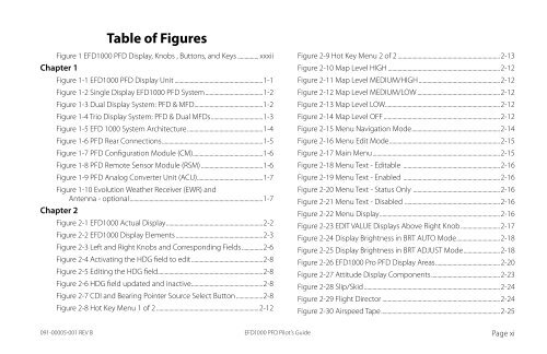
Table of Figures<br />
Figure 1 EFD1000 PFD <strong>Display</strong>, Knobs , Buttons, and Keys................ xxxii<br />
Chapter 1<br />
Figure 1-1 EFD1000 PFD <strong>Display</strong> Unit................................................................1-1<br />
Figure 1-2 Single <strong>Display</strong> EFD1000 PFD System.........................................1-2<br />
Figure 1-3 Dual <strong>Display</strong> System: PFD & MFD.................................................1-2<br />
Figure 1-4 Trio <strong>Display</strong> System: PFD & Dual MFDs.....................................1-3<br />
Figure 1-5 EFD 1000 System Architecture......................................................1-4<br />
Figure 1-6 PFD Rear Connections........................................................................1-5<br />
Figure 1-7 PFD Configuration Module (CM)..................................................1-6<br />
Figure 1-8 PFD Remote Sensor Module (RSM).............................................1-6<br />
Figure 1-9 PFD Analog Converter Unit (ACU)...............................................1-7<br />
Figure 1-10 Evolution Weather Receiver (EWR) and<br />
Antenna - optional...............................................................................................1-7<br />
Chapter 2<br />
Figure 2-1 EFD1000 Actual <strong>Display</strong>.....................................................................2-2<br />
Figure 2-2 EFD1000 <strong>Display</strong> Elements...............................................................2-3<br />
Figure 2-3 Left and Right Knobs and Corresponding Fields ...............2-6<br />
Figure 2-4 Activating the HDG field to edit...................................................2-8<br />
Figure 2-5 Editing the HDG field...........................................................................2-8<br />
Figure 2-6 HDG field updated and inactive...................................................2-8<br />
Figure 2-7 CDI and Bearing Pointer Source Select Button....................2-8<br />
Figure 2-8 Hot Key Menu 1 of 2..........................................................................2-12<br />
Figure 2-9 Hot Key Menu 2 of 2..........................................................................2-13<br />
Figure 2-10 Map Level HIGH.................................................................................2-12<br />
Figure 2-11 Map Level MEDIUM/HIGH...........................................................2-12<br />
Figure 2-12 Map Level MEDIUM/LOW............................................................2-12<br />
Figure 2-13 Map Level LOW..................................................................................2-12<br />
Figure 2-14 Map Level OFF....................................................................................2-12<br />
Figure 2-15 Menu Navigation Mode...............................................................2-14<br />
Figure 2-16 Menu Edit Mode...............................................................................2-15<br />
Figure 2-17 Main Menu...........................................................................................2-15<br />
Figure 2-18 Menu Text - Editable ......................................................................2-16<br />
Figure 2-19 Menu Text - Enabled .....................................................................2-16<br />
Figure 2-20 Menu Text - Status Only ..............................................................2-16<br />
Figure 2-21 Menu Text - Disabled ....................................................................2-16<br />
Figure 2-22 Menu <strong>Display</strong>......................................................................................2-16<br />
Figure 2-23 EDIT VALUE <strong>Display</strong>s Above Right Knob............................2-17<br />
Figure 2-24 <strong>Display</strong> Brightness in BRT AUTO Mode...............................2-18<br />
Figure 2-25 <strong>Display</strong> Brightness in BRT ADJUST Mode..........................2-18<br />
Figure 2-26 EFD1000 Pro PFD <strong>Display</strong> Areas..............................................2-20<br />
Figure 2-27 Attitude <strong>Display</strong> Components.................................................2-23<br />
Figure 2-28 Slip/Skid..................................................................................................2-24<br />
Figure 2-29 <strong>Flight</strong> Director.....................................................................................2-24<br />
Figure 2-30 Airspeed Tape.....................................................................................2-25<br />
091-00005-001 REV B<br />
EFD1000 PFD Pilot’s Guide<br />
Page xi