Aspen Primary Flight Display - Langley Flying School
Aspen Primary Flight Display - Langley Flying School
Aspen Primary Flight Display - Langley Flying School
You also want an ePaper? Increase the reach of your titles
YUMPU automatically turns print PDFs into web optimized ePapers that Google loves.
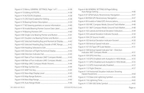
Figure 4-72 Menu, GENERAL SETTINGS, Page 1 of 7.............................4-38<br />
Figure 4-73 Editing AUTOCRS..............................................................................4-38<br />
Figure 4-74 AUTOCRS Disabled..........................................................................4-38<br />
Figure 4-75 CRS Field Enabled for Editing....................................................4-38<br />
Figure 4-76 Bearing Pointer Description.......................................................4-39<br />
Figure 4-77 NO bearing pointers or source information....................4-40<br />
Figure 4-78 Invalid Bearing Pointer Source Data Label.......................4-40<br />
Figure 4-79 Bearing Pointers OFF......................................................................4-40<br />
Figure 4-80 Single-Line Bearing Pointer and Button.............................4-41<br />
Figure 4-81 Double-Line Bearing Pointer and Button..........................4-41<br />
Figure 4-82 Selected Heading Bug and Numerical <strong>Display</strong>..............4-42<br />
Figure 4-83 Selected Heading Bug Outside of ARC Range...............4-42<br />
Figure 4-84 Heading Selected to Edit.............................................................4-42<br />
Figure 4-85 Direction of <strong>Flight</strong> Numerical <strong>Display</strong>..................................4-43<br />
Figure 4-86 Direction Indicator Fail..................................................................4-43<br />
Figure 4-87 Rate of Turn Indicator (360° Compass Mode).................4-43<br />
Figure 4-88 Rate of Turn Indicator (ARC Compass Mode)..................4-43<br />
Figure 4-89 Map (ARC Compass Mode Shown).......................................4-44<br />
Figure 4-90 Map Symbol Set................................................................................4-44<br />
Figure 4-91 MAP Hot Key........................................................................................4-45<br />
Figure 4-92 New Map <strong>Display</strong> Level ...............................................................4-45<br />
Figure 4-93 Map Range Buttons........................................................................4-45<br />
Figure 4-94 New Map Range...............................................................................4-45<br />
Figure 4-95 Auto Range Mode............................................................................4-46<br />
Figure 4-96 GENERAL SETTINGS B Page Editing<br />
Auto Range Setting...........................................................................................4-46<br />
Figure 4-97 GPS# Failure, Reversionary Navigation................................4-47<br />
Figure 4-98 RSM GPS Reversionary Navigation .......................................4-47<br />
Figure 4-99 Invalid or Failed GPS Annunciations.....................................4-48<br />
Figure 4-100 ARC Compass Mode, Ground Track Marker..................4-48<br />
Figure 4-101 360° Compass Mode, Ground Track Marker..................4-48<br />
Figure 4-102 Lateral and Vertical Deviation Indicators........................4-49<br />
Figure 4-103 Lateral Deviation Indicator Exceed.....................................4-50<br />
Figure 4-104 LDI Source Invalid..........................................................................4-50<br />
Figure 4-105 Vertical Deviation Indicator Exceed...................................4-50<br />
Figure 4-106 Vertical Speed Indicator.............................................................4-51<br />
Figure 4-107 VSI Tape Off-Scale Marker.........................................................4-51<br />
Figure 4-108 Vertical Speed Indicator Fail – Direction<br />
Indicator 360° Compass Mode...................................................................4-51<br />
Figure 4-109 GPSS Hot Key....................................................................................4-54<br />
Figure 4-110 GPSS Enabled with Autopilot in HDG Mode................4-55<br />
Figure 4-111 GPSS Disabled and Autopilot in HDG Mode................4-55<br />
Figure 4-112 GPSS Automatically Disabled.................................................4-57<br />
Figure 4-113 <strong>Flight</strong> Director..................................................................................4-57<br />
Figure 4-114 Horizontal Situation Indicator Showing<br />
Hazard Awareness ............................................................................................4-64<br />
Figure 4-115 Data Link Lightning Symbol...................................................4-65<br />
Figure 4-116 Lightning Time................................................................................4-65<br />
Figure 4-117 WX-500 Strike Symbol ...............................................................4-65<br />
091-00005-001 REV B<br />
EFD1000 PFD Pilot’s Guide<br />
Page xv


