English - Summa Online
English - Summa Online
English - Summa Online
- No tags were found...

You also want an ePaper? Increase the reach of your titles
YUMPU automatically turns print PDFs into web optimized ePapers that Google loves.
<strong>Summa</strong>Cut Series Cutters<br />
User’s Manual<br />
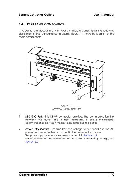
1.4. REAR PANEL COMPONENTS<br />
In order to get acquainted with your <strong>Summa</strong>Cut cutter, read the following<br />
description of the rear panel components. Figure 1-1 shows the location of the<br />
main components.<br />
FIGURE 1-1:<br />
SUMMACUT SERIES REAR VIEW<br />
1. RS-232-C Port.- This DB-9P connector provides the communication link<br />
between the cutter and a host computer. It allows bidirectional<br />
communication between the host computer and the cutter.<br />
2. Power Entry Module.- The fuse box, the voltage select board and the AC<br />
power cord receptacle are located in the power entry module.<br />
The power-up procedure is explained in detail in Section 1.6.<br />
For information on the conversion of the cutter’ s operating voltage, see<br />
Section 3.2.<br />
General Information 1-10