Hermetic Compressor - Tecumseh
Hermetic Compressor - Tecumseh
Hermetic Compressor - Tecumseh

You also want an ePaper? Increase the reach of your titles
YUMPU automatically turns print PDFs into web optimized ePapers that Google loves.
94 SERVICE HANDBOOK<br />
Starting a System with Liquid Refrigerant in the <strong>Compressor</strong><br />
When most air conditioning and commercial systems are started up for the first time each season,<br />
a large part of the system refrigerant charge is in the compressor. If there is no crankcase heater<br />
or the heat is not operating properly and the unit must be started at the time of the service, then<br />
follow these guidelines:<br />
• DO NOT attempt to heat the crankcase by applying a flame to the compressor. Not<br />
only is this process slow and likely to be ineffective, it may damage electrical wires,<br />
paint, and the oil.<br />
• If there is no evidence of a compressor electrical problem (for example, tripped breaker<br />
or blown fuse or reports of such), then “jog” the compressor. To “jog” the compressor,<br />
apply power for one to two seconds, then wait 1 to 2 minutes. After 3 or 4 jogs, apply<br />
power continuously.<br />
WARNING! Jogging a compressor that has an electrical problem can increase the<br />
likelihood of terminal venting. To reduce the risk of serious burns or death from terminal<br />
venting with ignition, you must FIRST check for a ground fault whenever you suspect an<br />
electrical problem. See “Identifying <strong>Compressor</strong> Electrical Problems” on pages 40-41 for<br />
additional information.<br />
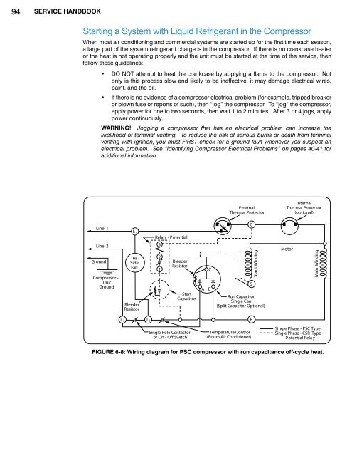
Line 1<br />
Line 2<br />
Ground<br />
<strong>Compressor</strong> -<br />
Unit<br />
Ground<br />
L 1<br />
Rela y - Potential<br />
L 2 T 2<br />
5<br />
Hi<br />
2<br />
Side<br />
Bleeder<br />
Fan<br />
Resistor<br />
1<br />
Start<br />
Capacitor<br />
Bleeder<br />
Resistor<br />
Single Pole Contactor<br />
or On - Off Switch<br />
A<br />
C<br />
B<br />
External<br />
Thermal Protector<br />
C<br />
Star t Winding<br />
Run Capacitor<br />
Single Can<br />
(Split Capacitor Optional)<br />
R<br />
Temperature Control<br />
(Room Air Conditioner)<br />
S<br />
Internal<br />
Thermal Protector<br />
(optional)<br />
Motor<br />
Main Winding<br />
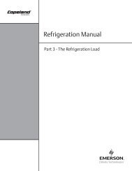
Single Phase - PSC Type<br />
Single Phase - CSR Type<br />
Potential Rela y<br />
FIGURE 6-8: Wiring diagram for PSC compressor with run capacitance off-cycle heat.