Hermetic Compressor - Tecumseh
Hermetic Compressor - Tecumseh
Hermetic Compressor - Tecumseh

You also want an ePaper? Increase the reach of your titles
YUMPU automatically turns print PDFs into web optimized ePapers that Google loves.
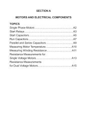
82 SERVICE HANDBOOK<br />
Service Valves<br />
As shipped with the compressors, the rotolock service valves have a small plastic dust plug inside<br />
the threaded end. Be sure to remove this plug before installing.<br />
Service valves on <strong>Tecumseh</strong> systems are “front seated” by turning the valve stem clockwise. This<br />
closes the valve and opens the gauge port.<br />
Turning the stem counter-clockwise “back seats” the valve and thus opens the system and closes<br />
the gauge port.<br />
If present, the valve port to the system control (high pressure cutout, low pressure control, fan<br />
control, etc.) is always open regardless of the position of the valve stem.<br />
If the system is to be operated with the service gauge functioning, it is necessary to “crack” the<br />
valve from its back seated position for the gauges to perform. Before removing the gauges, close<br />
the gauge port by returning the valves to their fully open position (back seated).<br />
Remember to check the packing gland nut (if present) on the stem for snugness before leaving the<br />
job. Install the cover nut over the valve stem as a secondary safeguard against leaks at the stem.<br />
Processing the System<br />
The performance and longevity of a refrigeration system is strongly influenced by how the system<br />
was “processed,” that is, how the system was prepared for operation at the time of installation.<br />
The procedure is:<br />
1. On split systems, install the liquid and suction line. See “Refrigerant Line Sizes” on<br />
pages 76-81 for recommended line sizes. A properly sized suction line accumulator is<br />
recommended. See “Accumulator Selection” on page 98 for accumulator sizing. Insulate<br />
the suction line to reduce heat exchange and excessive return gas temperatures<br />
to the compressor.<br />
2. To prevent oxidation and scale forming inside the tubes, it is good practice to flow dry<br />
nitrogen through the tubing during the soldering operations. A light flow of about ¼<br />
cubic feet per minute is sufficient.<br />
3. Install a properly sized filter-drier in the liquid line immediately ahead of the capillary<br />
tube or thermostatic expansion valve (TEV).<br />
4. A properly sized suction line filter-drier is recommended to protect the compressor. A<br />
suction accumulator must be installed on those systems having defrost cycles (heat<br />
pumps, low temperature refrigeration) or the likelihood of periodic floodbacks (bulk<br />
milk coolers, ice machines). See “Accumulator Selection” on page 98 for accumulator<br />
sizing.<br />
5. Pressure test the system for leaks using the safety precautions outlined in “System<br />
Flushing, Purging, and Pressure Testing for Leaks” on pages 4-5. Do not pressurize<br />
the system beyond 150 psig field leak test pressure.<br />
6. Use a vacuum pump (not the compressor) to draw a vacuum of 500 microns or less<br />
from both sides of the system. Entry must be made to both the high and low sides of<br />
the system to properly evacuate that portion of the system. Use a good micron gauge<br />
to measure the vacuum. An accurate reading cannot be made with a refrigeration<br />
gauge.<br />
WARNING! Never use a compressor to evacuate a system. Instead, use a high vacuum<br />
pump specifically designed for that purpose. Never start the compressor while it is<br />
under deep vacuum. Always break a vacuum with refrigerant charge before energizing<br />
the compressor. Failure to follow these instructions can damage the hermetic terminal<br />
and may result in terminal venting. As always, to reduce the risk of serious injury or<br />
death from fire due to terminal venting, never energize the compressor unless the protective<br />
terminal cover is securely fastened.