Hermetic Compressor - Tecumseh
Hermetic Compressor - Tecumseh
Hermetic Compressor - Tecumseh

Create successful ePaper yourself
Turn your PDF publications into a flip-book with our unique Google optimized e-Paper software.
25<br />
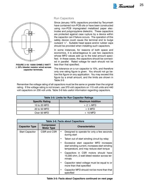
FIGURE 3-18: 15000 OHMS 2 WATT<br />
± 20% bleeder resistor wired across<br />
capacitor terminals.<br />
Run Capacitors<br />
Since January 1979, capacitors provided by <strong>Tecumseh</strong><br />
have contained non-PCB oils or have been constructed<br />
using non-PCB impregnated metallized paper electrodes<br />
and polypropylene dielectric. These capacitors<br />
are protected against case rupture by a device within<br />
the capacitor can if failure occurs. The operation of this<br />
safety device could cause the terminal end to bulge<br />
outward ½”. Suitable head space and/or rubber caps<br />
should be provided when installing such capacitors.<br />
In some instances, for reasons of both space and<br />
economics, it is advantageous to use two capacitors<br />
whose MFD values add up to the total amount specified.<br />
In these cases, the capacitors should be connected<br />
in parallel. Rated voltage for each should not be<br />
less than that specified.<br />
The tolerance on a run capacitor is 10%, and therefore<br />
only one rating figure is given. You should not go below<br />
this figure on any application. You may exceed this<br />
figure by a small amount, and the limits are shown in<br />
Table 3-5:<br />
Remember the voltage rating of all capacitors must be the same or greater than the original<br />
rating. If the voltage rating is not known, use 370 volt capacitors on 115 volt units and 440<br />
volt capacitors on 230 volt units. Table 3-6 lists useful information regarding capacitors.<br />
Table 3-5: Limits for Run Capacitor Ratings<br />
Specific Rating<br />
Maximum Addition<br />
10 to 20 MFD + 2 ½ MFD<br />
20 to 50 MFD + 5 MFD<br />
Over 50 MFD<br />
+ 10 MFD<br />
Table 3-6: Facts about Capacitors<br />
Capacitor Type<br />
<strong>Compressor</strong><br />
Motor Type<br />
Characteristics<br />
Start Capacitor CSIR and CSR • Designed to operate for only a few seconds<br />
during start<br />
• Taken out of start winding circuit by relay<br />
• Excessive start capacitor MFD increases<br />
start winding current, increases start winding<br />
temperature, and may reduce start torque<br />
• Capacitors in CSR motors should have<br />
15,000 ohm, 2 watt bleed resistor across terminals<br />
• Capacitor rated voltage must be equal to or<br />
more than that specified<br />
• Capacitor MFD should not be more than that<br />
specified<br />
Table 3-5: Facts about Capacitors continued on next page