SK-ACPE - Secura Key
SK-ACPE - Secura Key
SK-ACPE - Secura Key

You also want an ePaper? Increase the reach of your titles
YUMPU automatically turns print PDFs into web optimized ePapers that Google loves.
<strong>SK</strong>-<strong>ACPE</strong><br />
User/Installation Manual
COPYRIGHT© 2013
<strong>SK</strong>-<strong>ACPE</strong> TABLE OF CONTENTS<br />
1. INTRODUCTION.......................................................................................................1<br />
Introduction to <strong>SK</strong>-ACP<br />
Card ID Numbers and Facility Codes<br />
Setting the Facility Codes<br />
2. INSTALLATION.........................................................................................................3<br />
Physical Installation<br />
Wiring......................................................................................................................4<br />
Power and Batteries................................................................................................5<br />
Readers<br />
Inputs<br />
Chassis Ground<br />
Outputs....................................................................................................................6<br />
LED Indicators<br />
Typical Door Installation Diagram/Cable Types......................................................7<br />
RS-232 Connections.................................................................................................8<br />
Tamper Switch<br />
RS-485 Connections...............................................................................................10<br />
Ethernet<br />
Programming the <strong>SK</strong>-<strong>ACPE</strong> with <strong>SK</strong>-NET<br />
3. FACTORY SETTINGS................................................................................................11<br />
4. READERS AND CARDS............................................................................................12<br />
Using <strong>Secura</strong> <strong>Key</strong> Readers and Cards<br />
Using Non-<strong>Secura</strong> <strong>Key</strong> Readers and Cards<br />
Ordering Additional Cards<br />
Setting Facility Codes<br />
APPENDIX A – Wiring and System Configurations..................................................... A-1<br />
APPENDIX B – System Components and Specifications.............................................. B-1<br />
APPENDIX C – Connecting a Modem to <strong>SK</strong>-<strong>ACPE</strong>........................................................ C-1<br />
APPENDIX D – Connecting an <strong>SK</strong>-<strong>ACPE</strong> to a Local Area Network..............................D-1<br />
APPENDIX E – <strong>SK</strong>-<strong>ACPE</strong> Troubleshooting Guide......................................................... E-1<br />
APPENDIX F – Preventing Lightning Damage.............................................................F-1<br />
APPENDIX G –What’s new, and what has not changed in the <strong>SK</strong>-<strong>ACPE</strong> .................G-1<br />
V070213 3322346 (7742)
<strong>SK</strong>-ACPe<br />
Installation & Operating Manual<br />
INTRODUCTION<br />
The <strong>SK</strong>-<strong>ACPE</strong> Advanced Control Panel is a highly sophisticated, yet simple to use, two door access control<br />
unit with built-in Ethernet communications. The unit accepts readers of almost any technology, with a Wiegand<br />
output up to 40 bits, including Proximity, Touch Card, Wiegand, Magnetic Stripe, Bar Code, Optical, and<br />
Biometric. Each of the two passageways controlled by the unit is completely independent of the other and<br />
is configured, programmed and viewed separately.<br />
Up to 100 <strong>SK</strong>-<strong>ACPE</strong> Panels may be linked together on a twisted pair (plus signal ground) RS-485 bus. When<br />
used with <strong>SK</strong>-NET software, a highly featured, easy to use, distributed intelligence access control system<br />
can be created.<br />
Each of the two passageways controlled by the <strong>SK</strong>-<strong>ACPE</strong> has two programmable inputs which may be<br />
programmed by the user to function as a Door Monitor, Tamper Monitor, Remote Open, Remote Inactive,<br />
Bell, Arming Circuit, or User Defined Input.<br />
Each of the two passageways controlled by the <strong>SK</strong>-<strong>ACPE</strong> has two outputs. One output is the “Latch Relay,”<br />
which operates the door locking or operating device. The other “Auxiliary Output” is programmable by the<br />
user to activate under one of several possible alarm or special conditions.<br />
<strong>SK</strong>-<strong>ACPE</strong> will control access for up to 65,535 individuals in 15 weekly time schedules (Time Zones)<br />
independently for each of the two passageways. Time Zones include a holiday schedule that is followed<br />
when one of the 32 user programmable holidays occur.<br />
Any Access Card may be designated as a “Limited Use” card, and its use may be restricted to allow access<br />
for a given number of days or weeks or for a given number of times.<br />
The <strong>SK</strong>-<strong>ACPE</strong> may be programmed with a PC. Transaction information is stored by the unit and may be<br />
downloaded to a PC, or serial printer. Up to 10,000 transactions are stored.<br />
Since the <strong>SK</strong>-<strong>ACPE</strong> has nonvolatile memory, reprogramming after a power loss is unnecessary.<br />
CARD ID NUMBERS AND FACILITY CODES<br />
Access cards used with the <strong>SK</strong>-<strong>ACPE</strong> have two encoded numbers: the ID number which is different on each<br />
card, and the Facility Code, (also called a system or site code) which is normally the same for all cards at<br />
a given site. When a card is read, the system first verifies the Facility Code, then it checks the ID Number<br />
against its internal “card list” in memory to see if the card is void or valid. It also checks the Time Zone, the<br />
card’s Antipassback status, and the Limited Use count.<br />
1
<strong>SK</strong>-ACPe<br />
Installation & Operating Manual<br />
SETTING THE FACILITY (SYSTEM) CODE<br />
IMPORTANT<br />
Before programming or using a new unit,<br />
the correct Facility Code must be set.<br />
When power is first applied, or when the reset button is pushed (see Figure 3) the LED on each of the two<br />
readers will flash red and green alternately. While the LED is flashing, present an Access Card with the proper<br />
facility code to one of the readers and remove it (note LED turns solid green for about 1 second and the beeper<br />
beeps to indicate that the card has been read). The <strong>SK</strong>-<strong>ACPE</strong> will “remember” the facility code and retain it<br />
until reprogrammed. It is not necessary to present the access card to the second reader since it is automatically<br />
set for both passageways. After setting the facility code, wait for the LED to stop flashing before attempting to<br />
use the reader.<br />
To change a facility code (or to set the facility code if the LED is not flashing red/green), momentarily depress<br />
the reset button. The LED indicator will flash red and green alternately. If the reset button is pushed, but<br />
no card is presented to the reader before the LED indicator times out, the facility code will be unchanged.<br />
In some cases it may be necessary for the unit to recognize more than one facility code. Typical instances<br />
are when it is necessary to read cards that work in two independent locations that already have different<br />
facility codes or when two different reader technologies are used in the same system, each of which has a<br />
different facility code.<br />
The <strong>SK</strong>-<strong>ACPE</strong> can be set to recognize up to sixteen different facility codes. To program multiple facility codes,<br />
follow the procedure above for programming a single facility code, but present a card with the second facility<br />
code (and additional facility codes if necessary) to the reader before the red/green LED indicator times out.<br />
Note that it is not generally recommended to combine sets of cards with different facility codes,<br />
because the unit cannot distinguish between access cards having different facility codes and the<br />
same ID number.<br />
For example, if you have two sets of cards numbered 1-100, with facility codes 12345 and 23456, and you<br />
delete cards 1 - 10 from the reader’s internal “card list,” then cards 1 - 10 with either facility code will be<br />
denied entry at the reader.<br />
2
<strong>SK</strong>-ACPe<br />
Installation & Operating Manual<br />
INSTALLATION<br />
CAUTION SHOULD BE TAKEN NOT TO TOUCH CIRCUIT BOARD OR ELECTRONIC COMPONENTS PRIOR<br />
TO AND DURING INSTALLATION TO AVOID ELECTRO-STATIC DISCHARGE (ESD) DAMAGE.<br />
Installing the <strong>SK</strong>-<strong>ACPE</strong><br />
1. Select a location for the <strong>SK</strong>-<strong>ACPE</strong> unit that is secure and sheltered from weather and extreme humidity.<br />
Choose a location that facilitates access to power and is reasonably close to the doors that are to<br />
be controlled (no further than 500 feet).<br />
2. Using the unit as a template, mark on the mounting surface the location of the four mounting holes.<br />
3. Install appropriate mounting hardware (anchors, retainers, etc.) to the mounting surface if necessary.<br />
4. Screw #6 or #8 mounting screws<br />
into the top 2 mounting holes of<br />
the mounting surface, leaving<br />
about 1/4” clearance.<br />
5. Place panel top key-way mounting<br />
holes over installed mounting<br />
screws and slide panel down.<br />
6. Tighten top mounting screws.<br />
7. Install two bottom mounting screws<br />
(see figure 2).<br />
8. Route cables into the enclosure<br />
through knockouts in sides or back<br />
of box, being careful not to nick<br />
or scrape insulation on any rough<br />
edges.<br />
figure 2<br />
3
BACK<br />
<strong>SK</strong>-ACPe<br />
Installation & Operating Manual<br />
Wiring<br />
The <strong>SK</strong>-<strong>ACPE</strong> unit is organized so that the wiring for door #1 is on the right side of the panel and the wiring<br />
for door #2 is on the left side of the panel (see figure 3).<br />
For ease of installation and servicing, plug-in terminal blocks are provided.<br />
6<br />
5<br />
4<br />
3<br />
2<br />
1<br />
9<br />
8<br />
7<br />
6<br />
5<br />
4<br />
3<br />
2<br />
1<br />
6<br />
5<br />
4<br />
3<br />
2<br />
1<br />
RED LED<br />
GREEN LED<br />
14 VDC<br />
SIG GND<br />
DATA 1<br />
DATA 0 J6<br />
IN 2<br />
COM<br />
IN 1<br />
NO<br />
COM<br />
NC<br />
NO<br />
COM<br />
NC<br />
NO<br />
COM<br />
NC<br />
NO<br />
COM<br />
NC<br />
J2<br />
J4<br />
OPTIONAL<br />
WiFi MODULE<br />
RESET<br />
BUTTON<br />
GND<br />
RS-485-A<br />
RS-485-B<br />
3<br />
2<br />
1<br />
J12<br />
JP1<br />
JUMPER JP1:<br />
2 & 3 ENABLES J7 & J11<br />
1 & 2 ENABLES<br />
WiFi MODULE<br />
<strong>SK</strong>-<strong>ACPE</strong><br />
J8<br />
1<br />
J7<br />
POWER -<br />
POWER +<br />
TAMPER<br />
TXD<br />
RTS<br />
CTS<br />
RXD<br />
GND<br />
8<br />
7<br />
6<br />
5<br />
4<br />
3<br />
2<br />
1<br />
J5<br />
DATA 0<br />
DATA 1<br />
SIG GND<br />
14 VDC<br />
GREEN LED<br />
RED LED<br />
J1<br />
J3<br />
J10<br />
NC<br />
COM<br />
NO<br />
NC<br />
COM<br />
NO<br />
IN 1<br />
COM<br />
IN 2<br />
NC<br />
COM<br />
NO<br />
NC<br />
COM<br />
NO<br />
J11<br />
1<br />
2<br />
3<br />
4<br />
5<br />
6<br />
1<br />
2<br />
3<br />
4<br />
5<br />
6<br />
7<br />
8<br />
9<br />
1<br />
2<br />
3<br />
4<br />
5<br />
6<br />
RJ 45<br />
ETHERNET<br />
CHASSIS GROUND TERMINAL<br />
CONNECT TO<br />
EARTH GROUND SUCH AS<br />
A 10’ COPPER GROUND STAKE<br />
(BEST) OR AC POWER GROUND<br />
USING A 10 or 12 AWG WIRE<br />
TO EARTH<br />
GROUND<br />
RS-485<br />
TO OTHER<br />
<strong>SK</strong>-<strong>ACPE</strong>s<br />
or TO HOST<br />
14 VDC (RED)<br />
GND (BLK)<br />
RS-232<br />
TO HOST<br />
16.5-24 VAC (50-60 HZ)<br />
16-24 VDC<br />
<strong>SK</strong>-TS-CP<br />
TAMPER<br />
SWITCH<br />
COIN CELL BATTERY INFORMATION<br />
MODEL: 3V CR 1225<br />
------------------------------<br />
CHANGING OR REMOVING<br />
THE BATTERY:<br />
USING A SUITABLE TOOL, REMOVE THE<br />
BATTERY FROM THE HOLDER BY PUSHING THE<br />
COIN CELL BATTERY FROM THE BACK SIDE<br />
figure 3<br />
4
<strong>SK</strong>-ACPe<br />
Installation & Operating Manual<br />
POWER & BATTERIES<br />
The <strong>SK</strong>-<strong>ACPE</strong> unit must be connected to a source of low voltage power. The <strong>SK</strong>-<strong>ACPE</strong> should NOT be connected<br />
to the same power supply that is providing power to an electric lock or strike. To power the <strong>SK</strong>-<strong>ACPE</strong>, you<br />
must use a power supply, which is properly rated for the panel, plus any connected equipment:<br />
<strong>SK</strong>-<strong>ACPE</strong> with RK-WM / RK-WS readers<br />
<strong>SK</strong>-<strong>ACPE</strong> with <strong>SK</strong>-WLSE-MOD<br />
Add RK-WL readers to either of the above<br />
24VDC, 500 mA or 16.5VAC 40VA transformer<br />
24VDC, 500 mA or 16.5VAC 40VA transformer<br />
16.5VAC 40VA transformer<br />
The basic configuration can be powered by the <strong>SK</strong>-ACP-PS, which includes a 24VDC 1A supply and a 4AH<br />
backup battery, or by a 16.5VAC 40VA transformer (<strong>SK</strong>-XFRMR)<br />
Terminals 7 & 8 on plug “J7” must be connected to 16.5 to 24 volts, AC or DC. You may also connect the<br />
<strong>SK</strong>-<strong>ACPE</strong> to 12 VDC, but in this case you must connect your power supply to the red (+) and black (-)<br />
wire leads on the lower left corner of the panel instead of the “J7” plug. If you use 12 VDC you cannot<br />
install a standby battery in the <strong>SK</strong>-<strong>ACPE</strong>.<br />
When 16.5 – 24 volts is used to power the <strong>SK</strong>-<strong>ACPE</strong>, you may connect the red and black wires to a 12 volt<br />
standby battery. Polarity (+/-) must be observed. The, 10” X 11” <strong>SK</strong>-<strong>ACPE</strong>-LE can accommodate batteries<br />
up to 4.0 Amp-hours<br />
Do not energize the <strong>SK</strong>-<strong>ACPE</strong> until all other connections are made.<br />
READERS<br />
<strong>SK</strong>-<strong>ACPE</strong> is designed to accept any reader or keypad with a standard Wiegand interface. The reader for door<br />
#1 is connected to plug “J5”, the reader for door #2 is connected to plug “J6”. (See figure 3) SUGGESTED<br />
CABLE IS Alpha 1296C. The <strong>SK</strong>-<strong>ACPE</strong> will provide up to 400mA to power each reader. If the readers you use<br />
require more current, an external power supply must be used.<br />
INPUTS<br />
Each reader may be associated with up to two auxiliary inputs. Inputs might include remote switches, door contact<br />
sensors, vehicle presence detectors, etc. If you connect inputs to the <strong>SK</strong>-<strong>ACPE</strong> you must define those inputs using<br />
<strong>SK</strong>-NET software (see <strong>SK</strong>-NET manual, section 5.31). Note that input 1 (#7) and input 2 (#9) share a common<br />
terminal (#8) on plugs “J1” and “J2”. All inputs are configured as normally open circuits. However, in many cases a<br />
“Door Monitor” input should be a normally closed circuit. To convert any input defined as “Door Monitor” to normally<br />
closed, you must reconfigure the inputs as Normally Closed, using the <strong>SK</strong>-NET software (see <strong>SK</strong>-NET Manual.)<br />
For testing and troubleshooting purposes, LED indicators are located on the circuit board near the input terminals,<br />
just below the LED Indicator for the Latch Relay. The LED lights when the input is in the alarm (off-normal) state.<br />
CHASSIS GROUND<br />
The <strong>SK</strong>-<strong>ACPE</strong> has a chassis ground terminal at the bottom of the PCBA just to the left of J8. This terminal<br />
must be connected to a good, reliable Earth ground, to enable the on-board gas tube surge<br />
suppressors to work effectively. If this is not done, damage to the controller may result. A crimptype<br />
wire lug is supplied with the unit. Secure the lug to the terminal using the provided screw. Crimp the<br />
ground wire to 10AWG stranded, insulated wire, and connect the wire to the closest Earth ground available,<br />
such as a 10-ft buried copper grounding stake, Building Electrical Ground, or a steel cold water pipe, which<br />
must be contiguous, with no PVC or ABS sections.<br />
5
<strong>SK</strong>-ACPe<br />
Installation & Operating Manual<br />
OUTPUTS<br />
Each door controlled by the <strong>SK</strong>-<strong>ACPE</strong> has two double pole, double throw relays associated with it. The “latch<br />
relays” are located on “J1” and “J2”, terminals 1-6. The “auxiliary relays” are located on “J3” and “J4”. One<br />
pole of the latch relay is typically used to open or close a circuit to unlock a door or activate a gate operator.<br />
The other pole of the latch relay operates simultaneously and may be used to shunt an alarm contact, start<br />
a video recorder, etc. The auxiliary relay may operate according to a variety of user-defined conditions.<br />
These must be programmed using <strong>SK</strong>-NET software (see <strong>SK</strong>-NET manual, section 5.33) NOTE: Two MOVs<br />
(metal-oxide varistors) are provided with each <strong>SK</strong>-<strong>ACPE</strong>. These must be installed between the “Common” and<br />
either the “Normally Open” or the “Normally Closed” terminals where power to the electric lock or strike is<br />
being switched (See Figures 6 and 7). For testing and troubleshooting purposes, an LED indicator is located<br />
on the circuit board adjacent to each relay. The LED lights when the relay is activated.<br />
COMMUNICATIONS JUMPER<br />
The jumper on pins 2 and 3 of Jumper connector JP1 must be installed to enable RS-232 communications<br />
at Jack J11 and J7. If the <strong>SK</strong>-WLSE-MOD Wireless network module is installed at J12, this jumper must be<br />
moved to pins 1 and 2 of JP1 to enable RS-232 communications with the wireless module.<br />
LED INDICATORS<br />
The <strong>SK</strong>-<strong>ACPE</strong> features 12 LED indicators, which will assist the installer when connecting, testing and<br />
troubleshooting the readers, inputs and outputs, power and communications wiring. These indicators and<br />
their functions are described in Figure 4.<br />
LED Locations & Legend<br />
WIRELESS<br />
ADAPTER COMMS**<br />
CPU & POWER STATUS*<br />
LED 1: WIRELESS ADAPTER COMMS<br />
BLUE BLINK - SEARCHING<br />
SOLID BLUE - CONNECTED<br />
LED 2: CPU & POWER STATUS<br />
GREEN BLINK - STATUS OK<br />
AMBER BLINK - AC POWER FAIL<br />
RED BLINK - BATTERY FAIL<br />
LED 3: READER 2 POWER SHORTED<br />
LED 4: READER 1 POWER SHORTED<br />
LED5: LATCH RELAY 2 ACTIVE<br />
LED 6: LATCH RELAY 1 ACTIVE<br />
LED 7: INPUT 2-2 ACTIVE<br />
LED 8: INPUT 2-1 ACTIVE<br />
LED 9: INPUT 1-1 ACTIVE<br />
LED 10: INPUT 1-2 ACTIVE<br />
LED 11: AUX RELAY 2 ACTIVE<br />
LED 12: AUX RELAY 1 ACTIVE<br />
LED 13: RS-485 HOST COMMS<br />
READER 2<br />
SHORTED<br />
READER 1<br />
SHORTED<br />
LATCH<br />
RELAY 2<br />
ACTIVE<br />
INPUT 2-1<br />
ACTIVE<br />
INPUT 2-2<br />
ACTIVE<br />
AUX<br />
RELAY 2<br />
ACTIVE<br />
RESET<br />
BUTTON<br />
LATCH<br />
RELAY 1<br />
ACTIVE<br />
INPUT 1-1<br />
ACTIVE<br />
INPUT 1-2<br />
ACTIVE<br />
AUX<br />
RELAY1<br />
ACTIVE<br />
RS-485<br />
HOST<br />
COMMS<br />
**WIRELESS COMMS<br />
BLUE BLINK - SEARCHING<br />
SOLID BLUE - CONNNECTED<br />
*CPU & POWER STATUS<br />
GREEN BLINK - ALL OK<br />
AMBER BLINK - AC POWER FAIL<br />
RED BLINK - BATTERY FAIL<br />
figure 4<br />
6
¿<br />
¿<br />
<strong>SK</strong>-ACPe<br />
Installation & Operating Manual<br />
TYPICAL DOOR INSTALLATION<br />
2<br />
DOOR MONITOR<br />
INPUT 1-2<br />
INPUT 1-1<br />
2<br />
2<br />
5<br />
1<br />
INPUT 2-1<br />
INPUT 2-2<br />
READER<br />
INPUT 2<br />
RELAY 2-1<br />
}<br />
TO<br />
2ND DOOR<br />
2<br />
REMOTE<br />
DOOR-<br />
OPEN<br />
SWITCH<br />
READER<br />
INPUT 1<br />
5<br />
3<br />
COMMUNICATIONS<br />
TO MODEM, PC,<br />
SERIAL PRINTER.<br />
<strong>SK</strong>-<strong>ACPE</strong><br />
4<br />
TO RS-485<br />
NETWORK<br />
L<br />
A<br />
T<br />
C<br />
H<br />
RK-WM<br />
1<br />
ELECTRIC<br />
STRIKE or<br />
MAG LOCK<br />
1<br />
1<br />
6<br />
1<br />
POWER<br />
XFMR or<br />
POWER<br />
SUPPLY<br />
POWER<br />
STRIKE OR<br />
MAGLOCK<br />
SUPPLY<br />
CABLE TYPES:<br />
1<br />
2<br />
3<br />
4<br />
5<br />
6<br />
2 COND, UNSHIELDED 16-18 AWG<br />
2 COND, UNSHIELDED 18-24 AWG<br />
6 COND, SHIELDED 18-24 AWG<br />
RS-485 - CAT 5 NETWORK CABLE OR TWO TWISTED PAIR<br />
6 CONDUCTOR SHIELDED, WITH NO TWISTED PAIRS<br />
CAT 5e OR 6 ETHERNET CABLE<br />
TO LOCAL AREA<br />
NETWORK<br />
Figure 5<br />
7
<strong>SK</strong>-ACPe<br />
Installation & Operating Manual<br />
PIN NUMBER CONNECTIONS<br />
<strong>SK</strong>-ACP ADVANCED CONTROL PANEL PC OR TERMINAL PRINTER MODEM<br />
SIGNAL DESCRIPTION J7 DB-25S<br />
(FEMALE) PIN #<br />
DB-9S<br />
(FEMALE) PIN #<br />
DB-25P<br />
(MALE) PIN #<br />
DB-25P<br />
(MALE) PIN#<br />
DB-9<br />
(MALE) PIN#<br />
SIGNAL GROUND 1 1 & 7 5 1 & 7 7 5<br />
RECEIVE DATS (RXD) 2* 2 3 N/C * 3 2<br />
CLEAR TO SEND (CTS) 3 4 7 20 8 1<br />
REQUEST TO SEND (RTS) 4 * 5 8 6 & 8 4 7<br />
TRANSMIT DATA (TXD) 5 3 2 3 2 3<br />
* FOR HARD-WIRED PRINTER MODE, CONNECT TERMINAL 2 TO TERMINAL 4.<br />
RS-232<br />
FIGURE 6<br />
You may connect RS-232 communications to the <strong>SK</strong>-<strong>ACPE</strong> either by using plug “J7”, terminals 1-5, or by plugging<br />
the RS-232E cable into the J11 jack at the lower right hand side of the circuit board (See figure 3). Note that<br />
jumper J1 must be installed on pins 2 and 3 to enable RS-232 communications at J7 and J11. RS-232 requires<br />
at least 5-conductor cable. SUGGESTED CABLE IS Belden 9535. RS-232 is used to connect the COM port<br />
of a PC to a single <strong>SK</strong>-<strong>ACPE</strong>, or as a gateway to a network of <strong>SK</strong>-<strong>ACPE</strong>s. (COM ports are typically DB9 male<br />
or DB25 male jacks on the back of a personal computer.) Newer computers may not have COM ports, in<br />
which case, you must purchase the <strong>SK</strong>-USB USB-to-serial converter, which plugs into a USB port on your<br />
computer and provides a DB-9 connector, which can be connected to the <strong>SK</strong>-<strong>ACPE</strong>-LE by using an <strong>SK</strong>-PLUG9<br />
pigtail, extending the cable as long as needed, using Belden 9535 or equivalent cable. When connecting a<br />
PC via RS-232 the distance from the panel to the computer should not exceed 100’. (For longer distances,<br />
see “RS-485” below.) A serial printer may also be connected to the RS-232 port of any <strong>SK</strong>-<strong>ACPE</strong>. This will<br />
allow all system transactions to be printed as they occur. (A printer may be connected to one <strong>SK</strong>-<strong>ACPE</strong> even<br />
if a computer is connected to another <strong>SK</strong>-<strong>ACPE</strong> in the same network.) An external modem might also be<br />
connected to the RS-232 port of an <strong>SK</strong>-<strong>ACPE</strong> for dial-up applications using <strong>SK</strong>-NET-MLD software. While any<br />
Hayes compatible 56K modem may be used, we highly recommend that you use the <strong>Secura</strong> <strong>Key</strong> <strong>SK</strong>-MDM.<br />
The <strong>SK</strong>-<strong>ACPE</strong> contains the configuration data, or “setup string” which allows this modem to be configured<br />
in the field without the use of a computer and without setting DIP switches. (See Appendix C for modem<br />
instructions.) Figure 5 shows the RS-232 pin connections for a PC, printer, or modem.<br />
TAMPER SWITCH<br />
The <strong>SK</strong>-<strong>ACPE</strong> includes an input for an enclosure Tamper Switch, and it also has an onboard beeper, which<br />
can provide an audible warning if the <strong>SK</strong>-<strong>ACPE</strong> enclosure is opened. The <strong>SK</strong>-<strong>ACPE</strong> is provided with a jumper<br />
wire across J1, inputs 1 & 6, which should be removed if the tamper switch will be used. The Tamper Switch is<br />
available as an accessory, <strong>SK</strong>-TS-CP, which can be fastened to the enclosure with three screws (included) and<br />
wired to J1, inputs 1 & 6. To stop the beeper from sounding during maintenance by authorized technicians,<br />
the tamper switch can be held down for about 20 seconds, and the beeping will stop (this will be reset again<br />
after the panel is closed.)<br />
8
<strong>SK</strong>-ACPe<br />
Installation & Operating Manual<br />
Installation of Metal Oxide Varistor<br />
with Electric Strike<br />
ACCESS<br />
CONTROL<br />
UNIT<br />
N.O.<br />
COM<br />
N.C.<br />
µ<br />
INSTALL<br />
MOV HERE<br />
STRIKE<br />
+<br />
_<br />
LOCK<br />
POWER<br />
SUPPLY<br />
AC or DC<br />
Install the enclosed 40-volt MOV (Metal Oxide Varistor) across the relay contacts in the access control unit,<br />
as shown. The Access Control Unit must have its own power supply.<br />
FIGURE 7<br />
Install the enclosed 40-volt MOV (Metal Oxide Varistor) across the relay contacts in the access control unit,<br />
as shown. The Access Control Unit must have its own power supply.<br />
Installation of Metal Oxide Varistor<br />
with Magnetic Lock<br />
ACCESS<br />
CONTROL<br />
UNIT<br />
N.O.<br />
COM<br />
N.C.<br />
µ<br />
INSTALL<br />
MOV HERE<br />
MAG<br />
LOCK<br />
+<br />
_<br />
LOCK<br />
POWER<br />
SUPPLY<br />
DC<br />
FIGURE 8<br />
9
<strong>SK</strong>-ACPe<br />
Installation & Operating Manual<br />
RS-485<br />
The RS-485 bus (Connector J8) is used to link multiple <strong>SK</strong>-<strong>ACPE</strong> units into a network. Where two or more <strong>SK</strong>-<strong>ACPE</strong>s<br />
are linked, you must run cable between the “J8” plugs on each panel. Terminals 1 & 2 must be a twisted pair<br />
of wires. SUGGESTED CABLE is Belden 1585A (CAT-5e). Terminal 3 is a “signal ground”. Normally, it does not<br />
need to be connected. However, if terminal 3 is used, it may be connected to one conductor of another twisted<br />
pair. This must be an insulated conductor and it should NOT be connected to earth ground.<br />
Where the distance from the PC to any one of the <strong>SK</strong>-<strong>ACPE</strong> units is greater than 100’, you may install an RS-232<br />
to RS-485 converter (<strong>Secura</strong> <strong>Key</strong> p/n NET-CONV-P) to the COM port of the computer. If your PC does not have a<br />
COM port you will need to purchase a USB-to-serial converter (<strong>SK</strong>-USB), and then connect the RS-485 converter<br />
to the USB converter. From the converter you then run RS-485 cable and connect it anywhere along the RS-485<br />
bus. The total RS-485 cable distance, including the distance between all <strong>SK</strong>-<strong>ACPE</strong>s, may be up to 4000’.<br />
Figure 9 shows how each <strong>SK</strong>-<strong>ACPE</strong> is connected to the RS-485 bus.<br />
<strong>SK</strong>-<strong>ACPE</strong><br />
Line B<br />
¿<br />
¿<br />
Line A<br />
DC SIGNAL GROUND<br />
(OPTIONAL)<br />
Earth Grounded Shield is highly recommended in environments subject to high voltage electrical discharge (i.e.<br />
lightning). Shield should be connected to earth ground only at one end of the cable. DC Signal ground may be<br />
necessary in networks with very long wire runs. DC Ground wire is NOT to be connected to earth ground.<br />
ETHERNET<br />
FIGURE 9<br />
The RJ45 Ethernet connector, located on the lower right-hand corner of the circuit board, is used to link individual<br />
<strong>SK</strong>-<strong>ACPE</strong> panels to a Local Area Network. You can use CAT 5e or CAT6 cable terminated with RJ45 jacks to<br />
connect each panel to a router, hub, or switch located up to 300 feet away. See Appendix D for information on<br />
how to configure the <strong>SK</strong>-<strong>ACPE</strong> for use on a LAN.<br />
PROGRAMMING THE <strong>SK</strong>-<strong>ACPE</strong> WITH <strong>SK</strong>-NET<br />
The <strong>SK</strong>-<strong>ACPE</strong> must be programmed with <strong>SK</strong>-NET software. Please refer to the <strong>SK</strong>-NET manual for<br />
programming instructions. (The <strong>SK</strong>-NET manual is available at www.securakey.com)<br />
10
<strong>SK</strong>-ACPe<br />
Installation & Operating Manual<br />
FACTORY SETTINGS<br />
When shipped from the factory, the <strong>SK</strong>-<strong>ACPE</strong> has the following settings:<br />
Facility Code<br />
All Cards<br />
Settings<br />
Time Zones<br />
Door Zone<br />
Holidays<br />
None*<br />
Time Zone 0 (void)<br />
No Limited Use Cards<br />
Latch timer = 1 Second<br />
APB Timer = 0 Minutes (off)<br />
Baud Rate = 38,400*<br />
Reader ID = (none)<br />
Password = 12345*<br />
Date = Undetermined*<br />
Time = Undetermined*<br />
APB = Timed Hard*<br />
Date Restrictions = None<br />
0 = Always Void<br />
1 = Always Valid (no restriction)<br />
2 = Mon - Fri, 8am - 5:30pm<br />
3 = Mon - Fri, 6am - 6pm<br />
4 = Sat & Sun, 24 hours<br />
5 = Sat & Sun, 6am - 6pm<br />
6 = Always Valid (Timed Antipassback)<br />
7 & Up = Mon-Sun, 6am - 6pm<br />
Off For All Time Segments<br />
None Set<br />
Daylight Savings<br />
Correction Automatic*<br />
Inputs 1<br />
Door Monitor<br />
2 Disabled<br />
Auxiliary Output Disabled<br />
Anti-Passback Parameters<br />
Reader (In/Out)<br />
None<br />
Daily APB Forgive Hour 00<br />
* Common to Panel, all other settings are per reader (2 readers per panel)<br />
11
<strong>SK</strong>-ACPe<br />
Installation & Operating Manual<br />
READERS AND CARDS<br />
USING <strong>SK</strong>-<strong>ACPE</strong> WITH SECURA KEY PROXIMITY READERS AND CARDS<br />
<strong>Secura</strong> <strong>Key</strong> offers proximity and contactless smart card readers in a variety of sizes for use with the <strong>SK</strong>-<strong>ACPE</strong><br />
panel. <strong>Secura</strong> <strong>Key</strong> readers read <strong>Secura</strong> <strong>Key</strong> cards only, except for the <strong>SK</strong>-RKDT readers, which read both<br />
<strong>Secura</strong> <strong>Key</strong> and most HID Proximity cards with non-proprietary pass-through formats, such as H10203<br />
(26-bit) or HN10001 (Northern 34-bit). <strong>Secura</strong> <strong>Key</strong> cards have two encoded numbers: the ID Number<br />
which is different on each card, and the Facility Code (also called a system or site code) which is normally<br />
the same for all cards at a given site. When a card is read, the system first verifies the Facility Code, then<br />
it checks the ID Number against its internal “card list” to see if the card is void or valid. It also checks the<br />
card’s Antipassback Status, Time Zone and Limited Use count.<br />
USING <strong>SK</strong>-<strong>ACPE</strong> WITH NON-SECURA KEY CARDS AND READERS<br />
<strong>SK</strong>-<strong>ACPE</strong> will accept data from any reader with an SIA Wiegand interface. When using non-<strong>Secura</strong> <strong>Key</strong><br />
readers and devices, SIA 26-bit Wiegand format will present the least problems. Formats with ID fields<br />
longer than 16 bits will not work properly with the <strong>SK</strong>-<strong>ACPE</strong>. Custom formats are setup using the <strong>SK</strong>-NET<br />
software (see the <strong>SK</strong>-NET software manual.) Contact <strong>Secura</strong> <strong>Key</strong> technical support with questions about<br />
custom format compatibility with <strong>SK</strong>-<strong>ACPE</strong>.<br />
ORDERING ADDITIONAL CARDS FOR YOUR SYSTEM<br />
The <strong>SK</strong>-<strong>ACPE</strong> can learn up to 16 different facility codes, but it is not generally recommended that you combine<br />
sets of cards with different Facility Codes in the same system. The <strong>SK</strong>-<strong>ACPE</strong> cannot distinguish between cards<br />
which have different Facility Codes and the same ID Number. For example, if you have a card with Facility<br />
Code A1 and ID Number 15 and you have a card with Facility Code B2 and ID Number 15, and the <strong>SK</strong>-<strong>ACPE</strong><br />
has been programmed to accept both Facility Codes, it will see these as the same card.<br />
When ordering additional cards it is recommended that you place a factory order specifying the existing<br />
Facility Code and beginning with the ID Number which is one higher than the highest card already in use.<br />
RESET<br />
BUTTON<br />
<strong>SK</strong>-<strong>ACPE</strong> CIRCUIT BOARD<br />
SETTING THE FACILITY CODE<br />
When power is first applied to the <strong>SK</strong>-<strong>ACPE</strong> the LED on each of the<br />
connected readers will flash alternately Red and Green. While the LED is<br />
flashing, hold an Access Card with the correct Facility Code near a reader<br />
for about one second. The LED should show a long Green flash and the<br />
reader will beep. If an additional Facility Code is to be entered, present<br />
an Access Card with that Facility Code in the same manner. Repeat for<br />
each Facility Code to be entered. Let the LED stop flashing Red/Green<br />
before attempting to use an Access Card.<br />
To change a Facility Code (or to set a Facility Code if the LED is not<br />
flashing Red/Green) momentarily depress the reset button on the<br />
<strong>SK</strong>-<strong>ACPE</strong>. Depressing the reset button will NOT erase memory<br />
or disrupt other programming.<br />
To add an additional Facility Code to a system, while retaining the existing Facility Code, you must depress the<br />
reset button and then present a card with each Facility Code to the readers while the Red/Green flashing is<br />
occurring. If you only present a card with the “new” Facility Code the system will “forget” the old Facility Code. It<br />
is only necessary to present an Access Card to one of the two readers connected to each <strong>SK</strong>-<strong>ACPE</strong> in the system.<br />
12
<strong>SK</strong>-ACPe<br />
Installation & Operating Manual<br />
APPENDIX A<br />
wiring and system configurations<br />
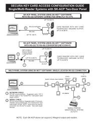
MULTI-PANEL SYSTEM USING <strong>SK</strong>-NET TM SOFTWARE- SINGLE LOCATION RS-232 CONNECTION<br />
DAISY CHAIN / MULTIDROP<br />
STAR /<br />
FANOUT<br />
<strong>SK</strong>-<strong>ACPE</strong><br />
“T”<br />
CONFIG<br />
<strong>SK</strong>-<strong>ACPE</strong><br />
<strong>SK</strong>-NET TM<br />
SOFTWARE<br />
USB<br />
¿<br />
<strong>SK</strong>-USB<br />
DB9<br />
2<br />
<strong>SK</strong>-PLUG9<br />
<strong>SK</strong>-<strong>ACPE</strong><br />
<strong>SK</strong>-<strong>ACPE</strong><br />
1<br />
<strong>SK</strong>-<strong>ACPE</strong><br />
<strong>SK</strong>-<strong>ACPE</strong><br />
<strong>SK</strong>-<strong>ACPE</strong><br />
<strong>SK</strong>-<strong>ACPE</strong><br />
¿<br />
1<br />
<strong>SK</strong>-<strong>ACPE</strong><br />
1<br />
2<br />
NETWORK CABLE:<br />
RS-485 communications. Suggested cable: CAT 5<br />
network cable or Two Twisted Pair. Total system cable<br />
length: 4,000 ft.<br />
SERIAL CABLE:<br />
RS-232 communications. Suggested cable: 6-Conductor,<br />
Shielded, with no twisted pairs. PC or serial printer. Total<br />
cable length 100 feet. NOTE: Same wire to be used for<br />
connection from <strong>SK</strong>-<strong>ACPE</strong> to reader. Total cable length<br />
500 feet. <strong>SK</strong>-USB may be required if your PC does not<br />
have a COM port.<br />
<strong>SK</strong>-<strong>ACPE</strong><br />
STUBBED<br />
¿<br />
2<br />
SERIAL PRINTER<br />
MONITORS ALL SYSTEM<br />
ACTIVITY*<br />
<strong>SK</strong>-<strong>ACPE</strong><br />
NOTE: Each <strong>SK</strong>-<strong>ACPE</strong> above can support 2 Wiegand output card readers.<br />
* See Appendix D for printer configuration.<br />
Figure A-1<br />
A-1
¿<br />
¿<br />
<strong>SK</strong>-ACPe<br />
Installation & Operating Manual<br />
MULTI-PANEL SYSTEM USING <strong>SK</strong>-NET TM SOFTWARE- SINGLE LOCATION RS-485 with CONVERTER<br />
<strong>SK</strong>-NET TM<br />
SOFTWARE<br />
¿<br />
USB<br />
<strong>SK</strong>-USB<br />
2<br />
NET-CONV-P<br />
RS-232-RS-485<br />
CONVERTER<br />
¿<br />
1<br />
<strong>SK</strong>-<strong>ACPE</strong><br />
<strong>SK</strong>-<strong>ACPE</strong><br />
1<br />
<strong>SK</strong>-<strong>ACPE</strong><br />
<strong>SK</strong>-<strong>ACPE</strong><br />
1<br />
2<br />
NETWORK CABLE:<br />
RS-485 communications. Suggested cable: CAT 5 network<br />
cable or Two Twisted Pair. Total system cable length: 4,000 ft.<br />
SERIAL CABLE:<br />
RS-232 communications. Suggested cable: 6-Conductor,<br />
Shielded, with no twisted pairs. PC or serial printer. Total cable<br />
length 100 feet. NOTE: Same wire to be used for connection<br />
from <strong>SK</strong>-<strong>ACPE</strong> to reader. Total cable length 500 feet. <strong>SK</strong>-USB<br />
may be required if your PC does not have a COM port.<br />
¿<br />
SERIAL PRINTER<br />
MONITORS ALL SYSTEM ACTIVITY*<br />
Note: When using the RS-232 to RS-485 converter, you cannot use the stubbed, star fanout or “T” configuration. All<br />
network connections from <strong>SK</strong>-<strong>ACPE</strong> to the next <strong>SK</strong>-<strong>ACPE</strong> must be in parallel with each other. The J8 connector, Pins 1<br />
and 2 must be a twisted pair. Pin 3 (Ground) is not connected.<br />
* See Appendix D for printer configuration.<br />
2<br />
MULTI LOCATION SYSTEM WITH <strong>SK</strong>-NET-MLD SOFTWARE<br />
1<br />
<strong>SK</strong>-<strong>ACPE</strong><br />
¿<br />
1<br />
¿<br />
<strong>SK</strong>-NET TM<br />
SOFTWARE<br />
NET-CONV-P<br />
MODEM<br />
TELCO LINE<br />
MODEM<br />
<strong>SK</strong>-MDM<br />
RS-232<br />
GATEWAY<br />
¿<br />
¿<br />
<strong>SK</strong>-<strong>ACPE</strong><br />
2 1<br />
¿<br />
<strong>SK</strong>-<strong>ACPE</strong><br />
<strong>SK</strong>-<strong>ACPE</strong><br />
<strong>SK</strong>-<strong>ACPE</strong><br />
<strong>SK</strong>-<strong>ACPE</strong><br />
Up to 100<br />
<strong>SK</strong>-<strong>ACPE</strong>’s<br />
A virtually unlimited number of remote locations<br />
can be set-up on one PC with <strong>SK</strong>-NET-MLD Software.<br />
See Appendix “C” setup instructions<br />
Up to 100<br />
<strong>SK</strong>-<strong>ACPE</strong>’s<br />
¿<br />
Figure A-2<br />
A-2
<strong>SK</strong>-ACPe<br />
Installation & Operating Manual<br />
MULTI-PANEL SYSTEM USING <strong>SK</strong>-NET TM SOFTWARE- SINGLE LOCATION WITH LAN CONNECTION<br />
NOTE: <strong>SK</strong>-NET-MLD software must be used when connecting more than one <strong>SK</strong>-<strong>ACPE</strong> to the LAN.<br />
<strong>SK</strong>-NET TM<br />
SOFTWARE<br />
¿<br />
NETWORK<br />
¿<br />
3<br />
DAISY CHAIN / MULTIDROP<br />
<strong>SK</strong>-<strong>ACPE</strong><br />
1<br />
<strong>SK</strong>-<strong>ACPE</strong><br />
STAR /<br />
FANOUT<br />
<strong>SK</strong>-<strong>ACPE</strong><br />
<strong>SK</strong>-<strong>ACPE</strong><br />
“T”<br />
CONFIG<br />
<strong>SK</strong>-<strong>ACPE</strong><br />
¿<br />
1<br />
<strong>SK</strong>-<strong>ACPE</strong><br />
<strong>SK</strong>-<strong>ACPE</strong><br />
<strong>SK</strong>-<strong>ACPE</strong><br />
<strong>SK</strong>-<strong>ACPE</strong><br />
1<br />
2<br />
3<br />
NETWORK CABLE:<br />
RS-485 communications. Suggested cable: CAT 5<br />
network cable or Two Twisted Pair. Total system cable<br />
length: 4,000 ft.<br />
SERIAL CABLE:<br />
RS-232 communications. Suggested cable: 6-Conductor,<br />
Shielded, with no twisted pairs. PC or serial printer. Total<br />
cable length 100 feet. NOTE: Same wire to be used<br />
for connection from <strong>SK</strong>-<strong>ACPE</strong> to reader. Total cable<br />
length 500 feet.<br />
ETHERNET CABLE:<br />
Standard Ethernet cable connector connected to<br />
existing LAN.<br />
<strong>SK</strong>-<strong>ACPE</strong><br />
STUBBED<br />
NOTE: Each <strong>SK</strong>-<strong>ACPE</strong> above can support 2 Wiegand output card readers.<br />
¿<br />
2<br />
<strong>SK</strong>-<strong>ACPE</strong><br />
SERIAL PRINTER<br />
MONITORS ALL SYSTEM<br />
ACTIVITY*<br />
* See Appendix D for printer configuration.<br />
Figure A-3<br />
A-3
<strong>SK</strong>-ACPe<br />
Installation & Operating Manual<br />
APPENDIX B<br />
SYSTEM components<br />
EQUIPMENT:<br />
ACCESSORIES:<br />
<strong>SK</strong>-<strong>ACPE</strong>:<br />
Two Door Access Control Unit with Ethernet connector<br />
NET-CONV-P — RS-232 to RS-485 Converter with<br />
Power Supply - one required per system (unless using<br />
a gateway connection)<br />
READERS/CARDS:<br />
RK-WM or RK-WS or RK-WL<br />
Proximity Readers (2 per <strong>SK</strong>-<strong>ACPE</strong>)<br />
RKCM-02 Molded Proximity Cards<br />
Specify Quantity<br />
or RKKT-02 <strong>Key</strong> Tags<br />
or RKCI-02 ISO Image-able cards<br />
ET4-WXM, ET4-WXS, ET8-RO-W-D, or ET8-RO-W-M<br />
Contactless Smart Card Reader (2 per <strong>SK</strong>-<strong>ACPE</strong>)<br />
ETCI ISO Image-able Contactless Smart Cards<br />
Specify Quantity<br />
or ETST <strong>Key</strong> Tags<br />
SOFTWARE:<br />
<strong>SK</strong>-NET — Basic Software<br />
<strong>SK</strong>-NET -MLD — Multi-Location Dial-Up Software<br />
<strong>SK</strong>-NET -MLD — C/S 2, 5,10,15<br />
Client/Server Software for Multiple Workstations<br />
<strong>SK</strong>-232E— Serial Cable Assembly<br />
For Bench Testing or field connection with a laptop<br />
<strong>SK</strong>-MDM — Modem - 56K Baud External Modem for<br />
dial-up connection to any <strong>SK</strong>-<strong>ACPE</strong> with MLD software<br />
<strong>SK</strong>-PLUG9 — Computer connector (DB9) with wire pigtail.<br />
<strong>SK</strong>-<strong>ACPE</strong>-PS — Transformer and stand by battery for<br />
<strong>SK</strong>-<strong>ACPE</strong>.<br />
<strong>SK</strong>-XFRMR – 16.5VAC 40VA Transformer for<br />
<strong>SK</strong>-<strong>ACPE</strong>-LE.<br />
<strong>SK</strong>-USB– Converts USB Port at PC to serial COM Port<br />
with DB9 connector<br />
<strong>SK</strong>-WLSE-MOD – Wireless LAN adapter, 802.11 b/g.<br />
Powered by <strong>SK</strong>-<strong>ACPE</strong>-LE. Connect at J12 and set<br />
jumpers.<br />
<strong>SK</strong>-TS-CP – Enclosure tamper switch. Connect to<br />
tamper input, J7 pin 1 & 6.<br />
<strong>SK</strong>-DCPWR- DC power supply, provides 1A@24VDC,<br />
also requires <strong>SK</strong>-XFRMR.<br />
dtk-cr - Surge protection for card readers and keypads<br />
dtk-xr - Surge protection for power, data and phone lines<br />
B-1
<strong>SK</strong>-ACPe<br />
PHYSICAL<br />
POWER REQUIREMENTS<br />
BACK-UP BATTERY<br />
CARD READERS<br />
Installation & Operating Manual<br />
SPECIFICATIONS<br />
<strong>SK</strong>-<strong>ACPE</strong>-LE<br />
Depth 3.0” (7.62 cm)<br />
Width 10.0” (25.40 cm)<br />
Height 11.0” (27.94 cm)<br />
Weight<br />
68.8 oz. (1.95 kg)<br />
Housing Material is All Steel; Color is Beige<br />
16.5-24VAC (50-60 HZ), 40 VA or 16-30 VDC, 500 mA<br />
If RK-WL readers are used, recommend a 16.5-24 VAC 40 VA transformer.<br />
A 12 VDC Power Supply may be used if connected to Battery Back-Up Leads.<br />
12 V, 4 Ah (Optional, Sold Separately)<br />
Connect two card readers with two-line Wiegand output, up to 40 bits. While the Card Data<br />
Format can vary, the Card ID bit length should not exceed 16 bits, which provides a maximum<br />
Card ID of 65,535. Provides 14 VDC, 400 mA max. power for each card reader.<br />
SOFTWARE <strong>SK</strong>-NET TM Software Version 3x or greater<br />
OUTPUTS - 2 Per Door (Total of 4) Latch & Alarm Shunt DPDT contact, 5A, up to 250 VAC or 30 VDC<br />
Auxiliary<br />
DPDT contact, 2A, up to 220 VAC or 30 VDC<br />
INPUTS - 2 Per Door (Total of 4) Auxiliary 1 Requires SPST contact closure<br />
Auxiliary 2<br />
Requires SPST contact closure<br />
COMMUNICATION RS-232 5-Wire Shielded Cable<br />
RS-485<br />
Single Twisted Pair, shielded cable with a signal ground<br />
Wiegand Input (2)<br />
Programmable up to 40 bits<br />
14 VDC @ 400 mA supplied to each reader,<br />
Modem<br />
Requires Hayes compatible - 1.2 to 38.4k baud<br />
Printer<br />
Serial Printer (or Parallel printer with serial converter)<br />
ENVIRONMENT Ambient Temperature -40° F to 158° F (-40° C to 70° C)<br />
Humidity<br />
0% to 95% relative humidity (non-condensing)<br />
OPERATIONAL Card Capacity 65,535 (Highest card number = 65,535)<br />
Time Zones<br />
15 for card access, one door unlock; full week plus<br />
holiday in one-half hour segments; 32 programmable<br />
holidays; selectable automatic daylight saving time.<br />
Facility Code Up to 16 different codes simultaneously (max. # of cards 65,535)<br />
Latch/Alarm Shunt Timer Programmable from 1/4 to 30 seconds<br />
Antipassback<br />
Real or Timed (1 to 30 minutes); hard or soft<br />
Auxiliary Inputs (2 Per Door) Programmable for door monitor, tamper monitor, remote<br />
open, remote inactive, bell, arming circuit or user defined<br />
Auxiliary Output (1 Per Door) Output is programmable to activate under one of many<br />
possible alarm conditions, time zone or card violations.<br />
Limited Use Cards<br />
65,535, programmable from 1-500 uses, days, weeks or<br />
number of days after first use.<br />
Transaction Storage<br />
10,000 events<br />
Memory<br />
Non-volatile<br />
This product complies with UL 294 Standards, CE (European Standards), and with Part 15 of Class B FCC Rules.<br />
B-2
¿<br />
<strong>SK</strong>-ACPe<br />
Installation & Operating Manual<br />
APPENDIX C<br />
CONNECTING A MODEM TO <strong>SK</strong>-<strong>ACPE</strong><br />
The <strong>SK</strong>-MDM (U.S. Robotics) has been preconfigured to work with <strong>Secura</strong> <strong>Key</strong> access control systems<br />
and <strong>SK</strong>-NET-MLD software. (NOTE: <strong>SK</strong>-NET-DM and the free download version of <strong>SK</strong>-NET do not<br />
support modem connections.) NOTE: This modem requires version 3.0 or later of <strong>SK</strong>-NET-MLD software.<br />
1. Plug the telephone cable provided into the <strong>SK</strong>-MDM and into the jack for a dedicated phone line.<br />
2. Plug the serial cable (provided) into the DB25 outlet on the <strong>SK</strong>-MDM.<br />
3. Connect the serial cable wires to the J-7 connector on the <strong>SK</strong>-<strong>ACPE</strong>.<br />
PANEL<br />
WIRE<br />
COLOR<br />
DB 25<br />
1 BLACK 7<br />
2 WHITE 3<br />
3 RED 8<br />
4 GREEN 4<br />
5 ORANGE 2<br />
4. Connect the modem power supply to the <strong>SK</strong>-MDM and plug into a 110VAC wall outlet.<br />
5. For added protection, the modem power lines, the phone line connection and the serial<br />
connection may be connected to suitable surge suppressors.<br />
6. Establish connection from the computer to the access control system using <strong>SK</strong>-NET-MLD software.<br />
(Follow instructions in the <strong>SK</strong>-NET manual.)<br />
REMOTE SITE MODEM CONFIGURATION WITH <strong>SK</strong>-<strong>ACPE</strong><br />
<strong>SK</strong>-MDM<br />
<strong>SK</strong>-<strong>ACPE</strong><br />
<strong>SK</strong>-<strong>ACPE</strong><br />
¿<br />
TELCO<br />
LINE<br />
MODEM<br />
RS-232<br />
GATEWAY<br />
RS-485<br />
NETWORK<br />
¿<br />
<strong>SK</strong>-<strong>ACPE</strong><br />
Up to 100 <strong>SK</strong>-<strong>ACPE</strong>’s<br />
¿<br />
Warranty: While <strong>Secura</strong> <strong>Key</strong> will be happy to help with modem-related problems, for best results<br />
contact a U.S. Robotics Service Center. To locate a convenient Service Center, go to www.usr.com.<br />
U.S. Robotics warrants this product for two years (detailed warranty is enclosed with the modem).<br />
Figure C-1<br />
C-1
<strong>SK</strong>-ACPe<br />
Installation & Operating Manual<br />
APPENDIX D<br />
CONNECTING AN <strong>SK</strong>-<strong>ACPE</strong> TO A LOCAL AREA NETWORK<br />
The <strong>SK</strong>-<strong>ACPE</strong>-LE control panel features a built-in Ethernet connection. The panel may be connected<br />
directly to a hub, switch or router on your Local Area Network up to 300 feet away.<br />
Alternately, you can use either the <strong>SK</strong>-WLSE-MOD Wireless Network Module (which connects with an<br />
802.11 wireless network.) This unit plugs into connector J12 on the <strong>SK</strong>-<strong>ACPE</strong>, and it receives its power<br />
from the panel. You must move the 2-pin jumper at J1 to pins 1 and 2 before installing the module.<br />
Refer to the Install/Setup documentation provided with the <strong>SK</strong>-WLSE-MOD for details on connections,<br />
IP addressing, setup and testing your network connection.<br />
To configure your system using <strong>SK</strong>-NET-MLD software, see <strong>SK</strong>-NET Manual Section 2 for instructions.<br />
NOTES:<br />
1) Always close <strong>SK</strong>-NET before closing WINDOWS ® to avoid LAN communications failures.<br />
2) The manufacturer’s instruction manual is included with the <strong>SK</strong>-WLSE-MOD. Keep this document<br />
for additional troubleshooting and setup information.<br />
Configuring IP Addresses in the <strong>SK</strong>-<strong>ACPE</strong><br />
Information you will need<br />
The <strong>SK</strong>-<strong>ACPE</strong> now has built-in Ethernet adapter which must be pre-configured with various IP addresses<br />
before connection to the LAN. Panels connected via RS232 or RS485 do not need to be<br />
configured with IP addresses.<br />
Before starting the setup procedure, contact your IT Manager or Network System Administrator for<br />
the following required information:<br />
TCP/IP Address (one for each panel connected with TCP/IP)<br />
Subnet Mask<br />
Default Gateway<br />
DNS Server<br />
Each address will consist of four groups of 3-digit numbers separated by periods (e.g.<br />
111.222.333.444)<br />
D-1
<strong>SK</strong>-ACPe<br />
Installation & Operating Manual<br />
Hardware Connection<br />
You must connect a Windows computer COM port to the J11 port on each <strong>SK</strong>-<strong>ACPE</strong>, using the<br />
RS-232E cable (or to J7 using a wire pigtail, see Figure 3). If your computer does not have a<br />
serial COM port, purchase and install the <strong>SK</strong>-USB USB-to-Serial Converter on your computer,<br />
and connect the DB9M connector on the converter to the DB9F connector on the RS-232E cable.<br />
You can configure the Ethernet adapter by either using <strong>SK</strong>-NET Terminal, which is included with<br />
the <strong>SK</strong>-NET software or by using HyperTerminal.<br />
Configuring the <strong>SK</strong>-<strong>ACPE</strong> Using <strong>SK</strong>-NET Terminal<br />
Follow these steps to configure your <strong>SK</strong>-<strong>ACPE</strong>.<br />
1. Connect your computer to the <strong>SK</strong>-<strong>ACPE</strong> being configured.<br />
2. Start <strong>SK</strong>-NET<br />
3. Right click on the Connection 1<br />
4. Select Properties<br />
5. Select the Connection tab<br />
6. Select Edit<br />
7. Select Test. The <strong>SK</strong>-<strong>ACPE</strong> Log On Screen displays (Fig D-1)<br />
8. Type in the Default Password 12345 and press Enter. The Device Configuration Screen (Fig<br />
D-2) will display: Ignore any IP addresses currently displayed – these are random values.<br />
9. At the prompt, you will enter data for items 1, 2, 3, and 4:<br />
10. Type 1, then type in the static IP address provided by the system administrator. Press Enter,<br />
then press Y to save changes.<br />
11. Type 2, then type in the subnet mask provided by the system administrator. Press Enter,<br />
then press Y to save changes.<br />
12. Type 3, then enter the default Gateway provided by the system administrator. Press Enter,<br />
then press Y to save changes.<br />
13. Type 4, then enter the DNS server provided by the system administrator.<br />
14. Press Enter, then press Y to save changes.<br />
15. Press ESC to exit, and the configuration is done. Your control panel is ready to connect to<br />
the LAN.<br />
16. Enter the IP address settings for each <strong>SK</strong>-<strong>ACPE</strong> into the <strong>SK</strong>-NET Properties screen for each<br />
Ethernet-connected panel.<br />
D-2
<strong>SK</strong>-ACPe<br />
Installation & Operating Manual<br />
Figure D-1. <strong>SK</strong>-<strong>ACPE</strong> Log-on Screen<br />
Figure D-2. <strong>SK</strong>-NET Device Configuration Screen<br />
CONFIGURING THE <strong>SK</strong>-<strong>ACPE</strong> FOR A SERIAL PRINTER<br />
A Serial Printer can be connected to any <strong>SK</strong>-<strong>ACPE</strong> in the system to monitor (print) all system transactions.<br />
The <strong>SK</strong>-<strong>ACPE</strong> must be configured for this function, using a terminal program, such as<br />
<strong>SK</strong>-NET Terminal or HyperTerminal.<br />
To configure an <strong>SK</strong>-<strong>ACPE</strong> for the serial transaction printer function:<br />
1. Follow Steps 1-7 in the previous section to display the <strong>SK</strong>-<strong>ACPE</strong> Login Screen (Figure D-1)<br />
2. Press CTRL-P (Ctrl key plus P key simultaneously), release, and then quickly press C. (These<br />
commands are non-case sensitive.)<br />
The <strong>SK</strong>-<strong>ACPE</strong> is now configured to send all system transactions to a serial printer connected at J7.<br />
D-3
<strong>SK</strong>-ACPe<br />
Installation & Operating Manual<br />
Using HyperTerminal to configure <strong>SK</strong>-<strong>ACPE</strong><br />
HyperTerminal is available free in Windows XP, but not in later Windows versions.<br />
Visit www.hilgreave.com to purchase HyperTerminal for use in Windows Vista, 7 or 8.<br />
Follow this procedure to configure HyperTerminal for the <strong>SK</strong>-<strong>ACPE</strong> TCP/IP setup:<br />
1. Connect your computer to the <strong>SK</strong>-<strong>ACPE</strong> being configured,<br />
2. Click on the Windows XP Start Button<br />
3. Select All Programs, then Select Accessories, Communications, then HyperTerminal<br />
4. The Location Information Screen will display, but it is not necessary for this setup procedure:<br />
click Cancel, then Yes to Confirm Cancel, and OK.<br />
5. The next screen is titled Connection Description. Enter a name and select any icon, then<br />
click OK.<br />
6. The Location Information Screen will redisplay, but it is not necessary for this setup procedure:<br />
click Cancel, then Yes to Confirm Cancel, and OK.<br />
7. The next screen titled Connect To: will have a parameter selection at the bottom titled<br />
“Connect Using:” Use the drop down box to select the COM port you are using to connect<br />
with <strong>SK</strong>-<strong>ACPE</strong>. Click OK<br />
8. The next screen which displays is COM x Properties which allows you to make Port Settings.<br />
Use the drop down boxes to select the following values: Bits per second = 38400, Data Bits<br />
= 8, Parity = None, Stop bits = 1, Flow Control = None, and then click OK<br />
9. The HyperTerminal main screen will display with the password prompt<br />
From this point, the configuration procedure is identical to the one used with <strong>SK</strong>-NET Terminal,<br />
described in the previous section.<br />
Consult the HyperTerminal documentation for procedures used with the Windows 7, 8 and Vista<br />
versions of HyperTerminal.<br />
D-4
<strong>SK</strong>-ACPe<br />
Installation & Operating Manual<br />
APPENDIX E<br />
<strong>SK</strong>-<strong>ACPE</strong> TROUBLESHOOTING GUIDE<br />
1.1 Cards do not work when creating a new Access Group<br />
1. Did you drag-and-drop readers into the new Access Group<br />
a. From the Explorer screen, click on All Readers.<br />
b. Drag-and-drop readers from the right side of the screen into the new Access Group.<br />
c. Click on the “+” sign next to the new Access Group to view the readers in the new group.<br />
d. Perform a Card Send, as described below.<br />
2. Did you send the cards to the Location<br />
a. Click on “Send Users Full”.<br />
1.2 New Transactions are not appearing in the Transaction Screen<br />
1. Are transactions being filtered<br />
a. From the Transaction screen, click on the Filter icon.<br />
b. Click on Defaults. Click OK.<br />
2. Are you logged in to the Location<br />
a. From the Explorer screen, open the All Readers folder to display reader icon(s). Are there<br />
Green check marks by each reader icon<br />
b. If readers do not have Green check marks (or have red lines through them), is there a Red<br />
arrow next to the Location icon<br />
c. If there is a Red arrow, but readers are not logged in, click on the Log-In icon on the toolbar.<br />
d. If there is not a Red arrow or a Green check mark, click on the location name, click on the Connect<br />
icon on the toolbar.<br />
3. Have you excluded any transactions<br />
a. Right click on All Readers.<br />
b. Click on the Transactions tab.<br />
c. View Transaction Types. If there is a check mark in the box located next to a Transaction<br />
Type, it will not be sent to your Transaction database in <strong>SK</strong>-NET.<br />
E-1
<strong>SK</strong>-ACPe<br />
Installation & Operating Manual<br />
1.3 “Invalid Facility Code” message when using newly-added cards<br />
1. Do the new cards have a different Facility Code than the previous ones<br />
a. Go to one of the <strong>SK</strong>-<strong>ACPE</strong> panels. Take a sample card with each different facility code. Press<br />
the reset button.<br />
b. Present a sample card with each Facility Code to one of the readers attached to the <strong>SK</strong>-<strong>ACPE</strong><br />
while the LED is flashing Red and Green.<br />
c. Repeat this process for each <strong>SK</strong>-<strong>ACPE</strong>. You can also send Facility codes to all panels through<br />
<strong>SK</strong>-NET, like this:<br />
d. From the Explorer screen, right click on the name of the reader that has the new Facility<br />
Code.<br />
e. Select Properties.<br />
f. Click on the Service tab. You should see the quantity of Facility Codes active in that panel.<br />
g. Under Facility Codes (Panel) click Edit.<br />
h. Click Close.<br />
i. Click Send To All.<br />
j. Click Close.<br />
k. After all cards are working, right click on All Readers.<br />
l. Select Backup. Select All Readers.<br />
1.4 Reader does not read-LED is Flashing Red or Green<br />
A slowly flashing Red LED indicates that the reader is in the Inactive mode. A slowly flashing Green LED indicates<br />
that the reader is in the Unlocked mode. These conditions exist when someone has activated a Door Control,<br />
from <strong>SK</strong>-NET, or when an input is shorted and programmed Remote Inactive or Remote Open. A flashing<br />
green LED also indicates the door has been unlocked by the Door Schedule. To check the door status:<br />
1. From the Explorer screen, right-click on the name of the reader.<br />
2. Select Properties.<br />
3. Click on the Door Controls tab.<br />
4. What is the Current Door State This will help identify why the reader is in the Inactive or<br />
Unlocked mode.<br />
5. Click on Normal if the reader shows Inactive Lock or Inactive Unlocked. This will change the Current Door State to<br />
Active Normal.<br />
6. Unlock via Door Schedule indicates the door is unlocked by the schedule. To disable the schedule<br />
click on Edit, click in the Disabled box and Send.<br />
E-2
<strong>SK</strong>-ACPe<br />
Installation & Operating Manual<br />
1.5 Lost Communications between PC and Readers<br />
1. Check Com Settings<br />
a. From the Explorer screen, right click on the Location Name.<br />
b. Select Properties.<br />
c. Click on the Connection Tab.<br />
d. Run the Connection Wizard.<br />
e. If the Wizard finds the connection, click OK and then Connect. If not, select your connection below.<br />
1. RS-232 direct connect, computer COM port to the <strong>SK</strong>-<strong>ACPE</strong> COM port. (See Section 1.6.)<br />
2. RS-232 to RS-485 converter, computer to converter to the <strong>SK</strong>-<strong>ACPE</strong>.<br />
(See Section 1.7.)<br />
3. TCP/IP connection via LAN, WAN. Contact the IT department.<br />
4. Modem connection, must have Local Connect unchecked and modem phone number provided.<br />
Try to repower the modem and <strong>SK</strong>-<strong>ACPE</strong>.<br />
2. Login Failure<br />
a. In the Explorer screen, look for a red arrow next to the Location icon. This indicates you are connected<br />
to the Location.<br />
b. Click on the “+” next to All Readers. If the reader shows a green check mark indicates the reader<br />
is logged in. An icon with a red “X” indicates lost communications with that reader. If this occurs,<br />
perform a Power Reset. (See Section 1.8)<br />
1.6 Using RS-232 Voltage Measurements to Check Communication Problems<br />
If you cannot connect, it will be necessary to take voltage measurements to identify whether the problem is<br />
with the <strong>SK</strong>-<strong>ACPE</strong> or with the computer.<br />
RS-232 Direct Connection<br />
1. From the Explorer screen, right-click on the Location.<br />
2. Select Properties.<br />
3. Click on the Connection tab.<br />
4. Uncheck the box next to “Gateway (RS-232)”<br />
5. Click on the Connect button.<br />
The system will fail to connect, but in the process it will open the computer COM port, making a voltage<br />
test possible.<br />
E-3
<strong>SK</strong>-ACPe<br />
Installation & Operating Manual<br />
1. Voltages: Measure voltages at the gateway reader’s terminal block, communications pins 1 to 5.<br />
Connect the ground lead to pin 1 (logic ground) for all measurements.<br />
a) Pin 2 (Receive Data, RXD). The voltage should read between -5 VDC to -12 VDC. This voltage comes<br />
from the PC. If the voltage is wrong or missing, disconnect the reader from the PC, and measure the<br />
voltages at the reader (should be 0.0 VDC) and at the PC (should be between -5 VDC to -12 VDC).<br />
b) Pin 3 (Clear to Send, CTS). The voltage should read between +5 VDC to +12 VDC. This voltage comes<br />
from the PC. If the voltage is wrong or missing, disconnect the reader from the PC, and measure the<br />
voltages at the reader (should be 0.0 VDC) and at the PC (should be between +5 VDC to +12 VDC).<br />
c) Pin 4 (Request to Send, RTS). The voltage should read between -5 VDC to -12 VDC. This voltage<br />
comes from the Card Reader. If the voltage is wrong or missing, disconnect the reader from the PC,<br />
and measure the voltages at the reader (should be -9.5 VDC) and at the PC (should be 0.0 VDC).<br />
d) Pin 5 (Transmit Data, TXD). The voltage should read between -5 VDC to -12 VDC. This voltage<br />
comes from the Card Reader. If the voltage is wrong or missing, disconnect the reader from the PC,<br />
and measure the voltages at the reader (should be -9.5 VDC) and at the PC (should be 0.0 VDC).<br />
After testing voltages, return to the Location/Properties/Connection box and re-check the box next to<br />
“Gateway (RS-232)”.<br />
1.7 NET-CONV Converter Connection<br />
If you cannot connect and you are connected using the NET-CONV converter, test voltages as follows:<br />
1. Measure input voltage from the converter power supply. It should be between 9 VDC and 16 VDC.<br />
2. Measure voltage between Ground (minus side of power supply) and TD (A). It should be 0 VDC.<br />
3. Measure voltage between Ground (minus side of power supply) and TD (B). It should be between<br />
2.5 VDC and 5 VDC.<br />
If these voltages are incorrect, contact <strong>Secura</strong> <strong>Key</strong> Technical Support.<br />
1.8 Power Reset<br />
Occasionally it may become necessary to perform a power reset on a <strong>SK</strong>-<strong>ACPE</strong> panel (for example, after a<br />
power surge.) The <strong>SK</strong>-<strong>ACPE</strong> has a multi-level power reset procedure, with options depending on how long<br />
you hold down the reset button following restoration of power. The Unit will beep, indicating the level of reset<br />
which has occurred.<br />
To perform a Power Reset:<br />
1. Disconnect power from the reader or panel (including any backup battery)<br />
2. Hold down the reset button.<br />
3. While holding the reset button, restore power, and continue holding the button until the unit beeps<br />
and the desired reset level occurs:<br />
One (1) beep will default the Baud rate to 38400 for the gateway (RS232), and (RS 485<br />
communications), exit the printer mode, reset password to 12345, and resend the wireless<br />
settings if being used.<br />
Two (2) beeps (3 seconds later) will change the node ID’s. This procedure will reset the node<br />
address, requiring a recovery procedure in <strong>SK</strong>-NET (see below).<br />
Three (3) beeps (15 seconds later) will perform a factory default for the panel.<br />
E-4
<strong>SK</strong>-ACPe<br />
Installation & Operating Manual<br />
Recovery Procedure:<br />
To clone the readers:<br />
1. From the Explorer screen, right click on the Location Name.<br />
2. Select New.<br />
3. Select Readers.<br />
4. Select Quick Find (with less than 20 readers), or Search if (with more than 20 readers).<br />
5. <strong>SK</strong>-NET will find the original reader(s) as new ones.<br />
6. Click OK to bring them into the system. Do not log in at this time.<br />
7. Look under All Readers and you will notice that you now have duplicate reader(s) names. The old<br />
one will still have the red X through the icon, and the new one will not.<br />
8. Drag and drop the New reader(s) on to the old reader(s) with the same name. You will be asked<br />
to Replace the reader, click Yes. This will clone the original reader settings in to the New reader.<br />
9. Right click on All Readers and select Login. Now all the readers should have a green check next to<br />
each reader.<br />
1.9 Replacing an <strong>SK</strong>-<strong>ACPE</strong><br />
When replacing or adding an <strong>SK</strong>-<strong>ACPE</strong> to a system, it is recommended to perform a “2-beep” power reset<br />
(See Sec. 1.8).<br />
NOTE: There are no changes required in <strong>SK</strong>-NET when replacing a card reader connected<br />
to the <strong>SK</strong>-<strong>ACPE</strong><br />
While replacing the <strong>SK</strong>-<strong>ACPE</strong> it is recommended that you note the serial number of the board being replaced<br />
along with the new board being used for the replacement. This will simplify the following steps used in this<br />
procedure.<br />
Note: DO NOT delete any readers from the Explorer screen!<br />
After completing the replacement of the board you need to start <strong>SK</strong>-NET, connect and login. Click on the +<br />
next to All Readers and you will notice a red X through the reader(s) icon(s) which have been replaced.<br />
1. Left click on All Readers, now it will be highlighted.<br />
2. At the top of the Explorer screen click on Explorer.<br />
3. Select View.<br />
4. Select Details. Notice that on the right hand side of the Explorer screen all of the readers are listed<br />
along with the Node ID, Logged In, Serial Number, Version, and Type.<br />
5. Right click on All Readers.<br />
6. Select New, Readers, Quick Find (for less than 20 readers) or Search (for more than 20 readers).<br />
7. After <strong>SK</strong>-NET finds the new readers, click OK to add them to the system (note that under All Readers<br />
the new readers found show the serial number as the name of the reader). Do not login.<br />
8. Look at the serial number or name of the new reader(s) and drag and drop the new one over the<br />
old one with the red X through the icon (be sure to include the “–1” or “–2” as part of the serial<br />
number).<br />
9. When asked ‘Do you wish to replace the reader’ Answer YES. <strong>SK</strong>-NET now will use the data<br />
files from the old reader and program them in to the new reader including sending cards.<br />
10. Repeat steps 8 and 9 for all readers being replaced.<br />
11. Test a card or two, the replacement is now complete.<br />
E-5
<strong>SK</strong>-ACPe<br />
Installation & Operating Manual<br />
APPENDIX F<br />
PREVENTING LIGHTNING DAMAGE<br />
SURGE PROTECTION FOR ACCESS CONTROL SYSTEMS<br />
Access Control equipment is susceptible to damage from lightning, especially when installed<br />
outdoors. Voltage spikes which travel through buried data cables, telephone lines or AC power<br />
lines can damage Access Control equipment indoors, as well.<br />
The <strong>SK</strong>-<strong>ACPE</strong>-LE is equipped with Gas Discharge Tube Surge Arrestors on the RS-485 communications<br />
lines (J8). For these devices to work properly, the <strong>SK</strong>-<strong>ACPE</strong> chassis ground (located on the circuit<br />
board, just to the left of J8) must be connected to a good Earth Ground such as a 10’ Copper<br />
Ground Stake (best) or AC Power Ground.<br />
While nothing can protect equipment from a direct lightning hit, surge protectors can help to minimize<br />
the damage caused by nearby lightning strikes. Surge protectors operate by connecting Transorbs<br />
or Varistors from data lines to ground. Surge protectors have no effect on normal circuit voltages,<br />
but can act quickly to divert large voltage spikes to ground and away from sensitive components.<br />
Although <strong>Secura</strong> <strong>Key</strong> equipment includes on-board surge suppression, properly grounded off-board<br />
devices will provide the best protection.<br />
Where to Install Surge Protection<br />
• On the AC line voltage input to the PC. (A UPS with surge protection is recommended).<br />
• On the AC line voltage input to any transformer or DC Power Supply connected to an <strong>SK</strong>-<strong>ACPE</strong> or Modem.<br />
• On RS-485 data lines connecting an <strong>SK</strong>-<strong>ACPE</strong> to a PC, or to other <strong>SK</strong>-<strong>ACPE</strong>’s.<br />
• On the power supply of a NET-CONV-P RS485 Converter (if used).<br />
• On RS-232 data lines from <strong>SK</strong>-<strong>ACPE</strong>s to PCs, Printers or Modems.<br />
• On Telephone lines connected to Modems.<br />
• On Data lines connecting card readers or keypads to the <strong>SK</strong>-<strong>ACPE</strong>s.<br />
Surge Protectors<br />
There are many manufacturers of surge protectors. Some are designed to protect a single type of<br />
circuit such as high voltage AC, low voltage DC or telephone lines. <strong>Secura</strong> <strong>Key</strong> offers two multifunction<br />
surge suppressors that are well-suited to protecting access control equipment. The DTK-XR<br />
is a good choice for protecting an <strong>SK</strong>-<strong>ACPE</strong> panel from power, data and telephone line surges. If<br />
the card readers or keypads attached to the <strong>SK</strong>-<strong>ACPE</strong> are located outdoors you may also wish to<br />
install DTK-CR protectors on each reader circuit. Wiring instructions for these surge protectors<br />
appears on pages F4 and F5.<br />
Protect Both Ends of Data Lines<br />
Surge Protectors should be installed at both ends of all Data Lines.<br />
F-1
<strong>SK</strong>-ACPe<br />
Installation & Operating Manual<br />
Wire Distance from the Surge Protector<br />
You must locate the protector at least three wire feet away from the device being protected. The<br />
additional wire resistance will dissipate the energy from leading edge of the spike. The wire can<br />
be coiled; a three-foot physical distance is not required.<br />
Grounding the Surge Protector<br />
Surge protectors must be connected to a verified good, nearby earth ground. This can be<br />
a 10’ Copper Ground Stake (best) or AC Power Ground. Run 10 AWG or 12 AWG wire as short a<br />
distance as possible, and avoid any bends in the wire.<br />
Self-grounding Surge Protectors<br />
Do not use surge protectors unless they are equipped with a separate ground wire or ground screw.<br />
Self-grounding Surge Protectors use the connector shell or Pin 1 as a ground path; however, the<br />
shell and Pin 1 are not always grounded.<br />
AC Power Surge Protectors<br />
AC Power Surge Protectors must be plugged into a properly grounded 3-wire socket. If a 3-wire<br />
socket is not available, have one installed by an electrician; do not use a 2-prong socket by cutting<br />
off the 3rd prong on the plug, or by using a 3/2 converter, or the surge protector will be rendered<br />
useless.<br />
Terminating Cable Shields<br />
Connect cable shields on data cables at one end only. You may terminate the cable shield to the<br />
same ground as the surge protector. Leave the cable shield unconnected at the opposite end.<br />
More Information<br />
For more information on lightning, including additional lightning protection methods and a US<br />
lightning density map, see <strong>Secura</strong> <strong>Key</strong> Applications Bulletin #28 on our website. (www.securakey.com)<br />
F-2
<strong>SK</strong>-ACPe<br />
Installation & Operating Manual<br />
CONNECTING THE DTK-CR (READER PROTECTION)<br />
The DTK-CR is a multi-line surge suppressor that can protect card readers and keypads from<br />
damaging power surges. It can be used between an <strong>SK</strong>-<strong>ACPE</strong> panel and any wiegand-output<br />
reader/keypad. This is especially useful where readers are located on gates and parking control<br />
equipment. It may also be used to protect standalone access control units.<br />
Locate the DTK-CR at least three (3) cable-feet away from the unit to be protected.<br />
Connect the green ground wire to a dependable earth ground, using a heavy gauge cable (12 or<br />
14 AWG recommended). Keep the wire run to the grounding location as short as possible.<br />
Wiegand-output Card Readers and <strong>Key</strong>pads<br />
Connect the Wiegand “0” and Wiegand “1” wires from the control panel to DATA IN. Connect the<br />
wiegand “0” and “1” wires from the reader to DATA OUT.<br />
Connect the reader power lines from the control panel to 5-12V IN. Connect the power wires from<br />
the reader to 5-12V OUT.<br />
Connect the “red” LED and “green” LED lines from the control panel to LED IN. Connect the “red”<br />
and “green” LED lines from the reader to LED OUT.<br />
If you are operating a 24 volt electric lock or strike, you can protect it also by connecting the lock<br />
power lines to 24V IN and OUT.<br />
F-3
<strong>SK</strong>-ACPe<br />
Installation & Operating Manual<br />
DTK-CR<br />
DIAGRAM 1<br />
EARTH<br />
GROUND<br />
J6<br />
J2<br />
J4<br />
6<br />
5<br />
4<br />
3<br />
2<br />
1<br />
9<br />
8<br />
7<br />
6<br />
5<br />
4<br />
3<br />
2<br />
1<br />
6<br />
5<br />
4<br />
3<br />
2<br />
1<br />
RED LED<br />
GREEN LED<br />
14 VDC<br />
SIG GND<br />
DATA 1<br />
DATA 0<br />
IN 2<br />
COM<br />
IN 1<br />
NO<br />
COM<br />
NC<br />
NO<br />
COM<br />
NC<br />
NO<br />
COM<br />
NC<br />
NO<br />
COM<br />
NC<br />
12 VDC<br />
GND<br />
12VDC<br />
RS-485A<br />
RS-R85B<br />
J9<br />
5<br />
4<br />
3<br />
2<br />
1<br />
RESET<br />
BUTTON<br />
WIEGAND<br />
IN<br />
<strong>SK</strong>-<strong>ACPE</strong><br />
GND<br />
A<br />
B<br />
J8<br />
3<br />
2<br />
1<br />
AC -<br />
AC+<br />
I/O<br />
TXD<br />
RTS<br />
CTS<br />
RXD<br />
GND<br />
J7<br />
8<br />
7<br />
6<br />
5<br />
4<br />
3<br />
2<br />
1<br />
DATA 0<br />
DATA 1<br />
SIG GND<br />
14 VDC<br />
GREEN LED<br />
RED LED<br />
NC<br />
COM<br />
NO<br />
NC<br />
COM<br />
NO<br />
IN 1<br />
COM<br />
IN 2<br />
NC<br />
COM<br />
NO<br />
NC<br />
COM<br />
NO<br />
J11<br />
1<br />
2<br />
3<br />
4<br />
5<br />
6<br />
1<br />
2<br />
3<br />
4<br />
5<br />
6<br />
7<br />
8<br />
9<br />
1<br />
2<br />
3<br />
4<br />
5<br />
6<br />
RS-232<br />
RJ 45<br />
ETHERNET<br />
J3<br />
J5<br />
J1<br />
24V<br />
24 LED 12 DATA<br />
DTK-CR<br />
STRIKE<br />
CARD<br />
READER<br />
CONNECTING THE DTK-XR (DATA LINE PROTECTION)<br />
The DTK-XR is a multi-line surge suppressor that can protect an <strong>SK</strong>-<strong>ACPE</strong> control panel, or other<br />
access control unit from damaging power surges.<br />
Locate the DTK-XR at least three (3) wire-feet away from the unit to be protected.<br />
Connect the green ground wire to a dependable earth ground, using a heavy gauge cable (12 or<br />
14 AWG recommended). Keep the wire run to the grounding location as short as possible.<br />
If you are using 24 volts to power the access control unit (recommended) connect the power supply<br />
to 24V IN and connect the access control unit to 24V OUT. If you are using 12 volts to power the<br />
access control unit, connect the power supply to 12V IN and connect the access control unit to<br />
12V OUT.<br />
F-4
<strong>SK</strong>-ACPe<br />
Installation & Operating Manual<br />
If the access control unit is connected to other units via RS-485 you may connect the “A” and “B”<br />
lines of the RS-485 twisted pair to 6V IN and 6V OUT.<br />
If you are using a dial-up modem, you may protect the modem by running the “Tip” (usually green)<br />
and “Ring” (usually red) phone lines to TELCO IN and connect the phone jack to TELCO OUT.<br />
DTK-XR<br />
DIAGRAM<br />
J6<br />
J2<br />
J4<br />
6<br />
5<br />
4<br />
3<br />
2<br />
1<br />
9<br />
8<br />
7<br />
6<br />
5<br />
4<br />
3<br />
2<br />
1<br />
6<br />
5<br />
4<br />
3<br />
2<br />
1<br />
RED LED<br />
GREEN LED<br />
14 VDC<br />
SIG GND<br />
DATA 1<br />
DATA 0<br />
IN 2<br />
COM<br />
IN 1<br />
NO<br />
COM<br />
NC<br />
NO<br />
COM<br />
NC<br />
NO<br />
COM<br />
NC<br />
NO<br />
COM<br />
NC<br />
12 VDC<br />
GND<br />
12VDC<br />
RS-485A<br />
RS-R85B<br />
J9<br />
5<br />
4<br />
3<br />
2<br />
1<br />
RESET<br />
BUTTON<br />
WIEGAND<br />
IN<br />
<strong>SK</strong>-<strong>ACPE</strong><br />
GND<br />
A<br />
B<br />
J8<br />
3<br />
2<br />
1<br />
AC -<br />
AC+<br />
I/O<br />
TXD<br />
RTS<br />
CTS<br />
RXD<br />
GND<br />
J7<br />
8<br />
7<br />
6<br />
5<br />
4<br />
3<br />
2<br />
1<br />
DATA 0<br />
DATA 1<br />
SIG GND<br />
14 VDC<br />
GREEN LED<br />
RED LED<br />
NC<br />
COM<br />
NO<br />
NC<br />
COM<br />
NO<br />
IN 1<br />
COM<br />
IN 2<br />
NC<br />
COM<br />
NO<br />
NC<br />
COM<br />
NO<br />
1<br />
2<br />
3<br />
4<br />
5<br />
6<br />
1<br />
2<br />
3<br />
4<br />
5<br />
6<br />
7<br />
8<br />
9<br />
1<br />
2<br />
3<br />
4<br />
5<br />
6<br />
RS-232<br />
RJ 45<br />
ETHERNET<br />
J5<br />
J1<br />
J3<br />
J11<br />
PHONE<br />
JACK<br />
DTK-XR<br />
TELCO 24V<br />
12V 6V<br />
EARTH<br />
GROUND<br />
TO NEXT PANEL<br />
TO PHONE CO.<br />
24VDC<br />
F-5
<strong>SK</strong>-ACPe<br />
Installation & Operating Manual<br />
APPENDIX G<br />
What’s new, and what has<br />
not changed in the <strong>SK</strong>-<strong>ACPE</strong><br />
The <strong>SK</strong>-<strong>ACPE</strong> is <strong>Secura</strong> <strong>Key</strong>’s replacement for the legendary <strong>SK</strong>-ACP.<br />
The “E” indicates the built-in Ethernet capability. The main reason for this<br />
upgrade is the obsoletion of the ACP’s 16-bit Hitachi main processor unit.<br />
Due to the large number of legacy systems in the field, we have designed the<br />
<strong>SK</strong>-<strong>ACPE</strong> as a drop-in replacement for the <strong>SK</strong>-ACP. While the <strong>SK</strong>-<strong>ACPE</strong> is almost<br />
functionally identical, we have also included some long-needed improvements<br />
made possible by the powerful new ARM Cortex M3, 32-bit RISC processor.<br />
1. This unit is functionally identical to the <strong>SK</strong>-ACP. It will work with older versions<br />
of <strong>SK</strong>-NET software, including Versions 3, 4 and 5.<br />
2. Connectors and their functions are identical to the <strong>SK</strong>-ACP. You can replace an<br />
older board with a new one without rewiring the connectors. Note that connectors<br />
J3 and J4 are now located on the side of the board.<br />
3. The Ethernet Adapter is now integrated into the panel. Connect to the LAN via<br />
RJ-45 connector J10 at the lower right-hand corner of the board. A separate module<br />
is not required. Multiple Ethernet connections in one system require <strong>SK</strong>-NET-MLD. IP<br />
Addresses must be configured using a terminal program (See Appendix D).<br />
4. Status LED functions and locations have been changed – see Figure 4 for details.<br />
5. The jumper that changes input circuits from NC to NO has been removed.<br />
On the <strong>SK</strong>-<strong>ACPE</strong>, this setting is now changed in the <strong>SK</strong>-NET software (Version 5.1 is<br />
required). If you do not have Version 5, the inputs will default to NC.<br />
6. A new Jumper JP1 enables RS-232 signals either at J12 or J11 and J10<br />
(See Fig. 3). Enabling RS-232 at J12 allows the use of the optional <strong>SK</strong>-WLSE-LAN<br />
wireless LAN Module. Enabling RS-232 at J11 and J10 allows the connection of a<br />
computer at the Field Service Port J11 or wiring of a serial connection to J10.<br />
The <strong>SK</strong>-WLSE-MOD is an entirely new module, and is not compatible with the<br />
<strong>SK</strong>-WLS-MOD module used with the <strong>SK</strong>-ACP.<br />
7. The RJ-11 Jack has been removed. The <strong>SK</strong>-QUICKCONN and <strong>SK</strong>-CBLSA cables<br />
cannot be used to connect a computer to the panel’s RS-232 port. A new cable,<br />
RS-232E, is required to connect a computer to the J11 Field Service Port.<br />
G-1
<strong>SK</strong>-ACPe<br />
Installation & Operating Manual<br />
8. The Reset Button has been moved – it is next to connector J2.<br />
9. AC Power is now recommended, due to a redesigned power supply. A 16.5VAC<br />
40VA transformer such as <strong>SK</strong>-XFRMR can be used to power the board. 24VDC power<br />
is also recommended, using a DC supply such as <strong>SK</strong>-DCPWR.<br />
10. Gas discharge tube surge protectors are now included on the RS-485 bus (J8)<br />
which interconnects multiple panels, and can be used to connect back to the host PC.<br />
These devices will greatly improve surge protection of the panel, but external surge<br />
protectors are still highly recommended in lightning-prone areas (see Appendix F4, F5).<br />
11. A Chassis Ground Terminal has been added to the PCBA (left of J8). To allow the<br />
on-board surge suppressors to discharge to ground, you must connect this terminal<br />
to Earth Ground, using the supplied ground lug and 10 AWG wire (see Figure 3).<br />
12. The panel now includes battery monitoring circuitry which can report low battery<br />
or AC failure conditions to <strong>SK</strong>-NET (Version 5.1 is required). These conditions are also<br />
indicated at LED 2.<br />
13. On-board memory has been increased, allowing up to 10,000 stored transactions<br />
to be buffered instead of 4800, and allowing up to 65,535 cardholders to be limited<br />
use cards instead of 4000 (<strong>SK</strong>-NET Version 5.1 is required).<br />
14. The panel now includes an enclosure tamper input (J7, pins 1&6) which can be<br />
connected to optional enclosure tamper switch <strong>SK</strong>-TS. (<strong>SK</strong>-NET Version 5.1 is required.)<br />
15. The Serial Transaction Printer function must now be configured using a Terminal<br />
Program. (See Appendix D).<br />
16. The Power Reset function has been enhanced (See Appendix E, section 1.8).<br />
G-2
<strong>SK</strong>-ACPe<br />
Installation & Operating Manual<br />
WARRANTY (U.S. and Canadian)<br />
“This product is warranted against defects in materials and workmanship for a period of 2 years from the date of<br />
purchase. <strong>Secura</strong> <strong>Key</strong> shall, at its option, replace the defective product with a new or refurbished product, if returned<br />
to us freight prepaid within the warranty period. This is subject to the equipment being installed in accordance<br />
with the instructions and used appropriately in suitable conditions. This warranty does not include freight, taxes,<br />
duties, or installation expenses. THE WARRANTY SET FORTH ABOVE IS EXCLUSIVE AND NO OTHER WARRANTY,<br />
WHETHER WRITTEN OR ORAL, IS EXPRESSED OR IMPLIED. SECURA KEY SPECIFICALLY DISCLAIMS ANY IMPLIED<br />
WARRANTIES OR MERCHANTABILITY AND FITNESS FOR A PARTICULAR PURPOSE. The remedies provided herein<br />
are the buyers’ sole and exclusive remedies. In no event shall <strong>Secura</strong> <strong>Key</strong> be liable for direct, indirect, special,<br />
incidental or consequential damages (including loss of profits), whether based on contract, tort or any other legal<br />
theory.” Contact <strong>Secura</strong> <strong>Key</strong> for Card/Tag and Export Warranty Policies. Return of 2-Year Warranty defective product is<br />
always required, and must be done within 30 days or customer account is subject to full cost of the replacement unit.<br />
Warranty Exclusions<br />
Products which have failed due to vandalism, willful damage, installation errors, inappropriate<br />
electrical loading, mis -use and “Acts of God” such as lightning, fire, flood, hurricane, etc.<br />
Cards that have been modified by third parties after sale in a manner that affects performance of the card. Reader<br />
Modules, Code Strips, Tags or Inserts that are embedded into other products - these are covered by a separate warranty<br />
– check with factory. Products where the serial number has been defaced or removed. Products not manufactured by<br />
<strong>Secura</strong> <strong>Key</strong> are covered by their own original manufacturers’ warranty. Please contact SECURA KEY Customer Service<br />
for warranty/repair instructions.<br />
INSTRUCTION TO THE USER<br />
WARNING:<br />
This equipment has been tested and found to comply with the limits for a class B digital device, pursuant to part 15 of<br />
the FCC Rules. These limits are designed to provide reasonable protection against harmful interference in a residential<br />
installation. This equipment generates, uses and can radiate radio frequency energy and if not installed and used in<br />
accordance with the instructions, may cause harmful interference to radio communications. However, there is no guarantee<br />
that interference will not occur in a particular installation. If this equipment does cause harmful interference to radio<br />
or television reception, which can be determined by turning the equipment off and on, the use is encouraged to try to<br />
correct the interference by one or more or the following measures:<br />
• Reorient or relocate the receiving antenna.<br />
• Increase the separation between the equipment and receiver.<br />
• Connect the equipment into an outlet of a circuit different from that to which the receiver is connected.<br />
• Consult the dealer or an experienced radio/TV technician for help.<br />
This equipment has been certified to comply with the limits for a class B computing device, pursuant to FCC Rules. In<br />
order to maintain compliance with FCC regulations, shielded cables must be used with this equipment. Operation with<br />
non-approved equipment or unshielded cables is likely to result in interference to radio and TV reception. The user is<br />
cautioned that changes and modifications made to the equipment without the approval of the manufacturer could void<br />
the user’s authority to operate this equipment.
20301 Nordhoff Street • Chatsworth, CA 91311<br />
Phone: 818-882-0020 • Fax: 818-882-7052<br />
TOLL FREE: 800-891-0020<br />
mail@securakey.com • www.securakey.com