Model MR Installation Manual - MTS Sensors
Model MR Installation Manual - MTS Sensors
Model MR Installation Manual - MTS Sensors

You also want an ePaper? Increase the reach of your titles
YUMPU automatically turns print PDFs into web optimized ePapers that Google loves.
<strong>Model</strong> <strong>MR</strong> Operation and <strong>Installation</strong> <strong>Manual</strong><br />
<strong>Model</strong> Number Identification - FM and CSA<br />
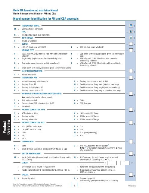
<strong>Model</strong> number identification for FM and CSA approvals<br />
Transmitter model = M 1<br />
m = Magnetostrictive transmitter<br />
Type = R 2<br />
r = Analog output liquid-level transmitter<br />
Input power = A 3<br />
a = 24 Vdc, 2-wire loop<br />
Product<br />
Overview<br />
Output = 4<br />
1 = 4-20 mA Single loop with HART 2 = 4-20 mA Dual loops with HART<br />
Housing type =<br />
a = NEMA Type 4X, 316L stainless steel with cable (intrinsically<br />
safe only)<br />
e = Dual cavity with display (explosion-proof and intrinsically<br />
safe)<br />
b = Single cavity (explosion-proof and intrinsically safe) l = NEMA Type 4X, 316L SS w/6-pin male connector<br />
(intrinsically safe only)<br />
c = Dual cavity (explosion-proof and intrinsically safe) 3 = NEMA Type 4X, 316L SS with internal terminal blocks<br />
(intrinsically safe only)<br />
d = Single cavity with display (explosion-proof and intrinsically safe)<br />
Electronics mounting =<br />
1 = Integral electronics<br />
Transmitter pipe =<br />
b = Industrial end-plug with stop collar f = Sanitary, drain-in-place, no hole, DN<br />
c = Sanitary, T-bar, TB h = Flexible w/bottom fixing hook (stainless steel only)<br />
d = Sanitary, drain-in-place, DP j = Flexible w/bottom fixing weight (stainless steel only)<br />
e = Sanitary, clean-in-place, CP k = Flexible w/bottom fixing magnet (stainless steel only)<br />
Materials of construction (wetted parts) =<br />
Note: contact factory for other materials<br />
1 = 316L stainless steel a = Teflon<br />
2 = Electropolished 316L stainless steel Ra 15 C = CRN Approved<br />
3 = Hastelloy C<br />
Process connection type =<br />
1 = NPT adjustable fitting 6 = 150 lb. welded RF flange<br />
4 = Sanitary, welded 7 = 300 lb. welded RF flange<br />
5 = Sanitary, adjustable 8 = 600 lb. welded RF flange<br />
Process connection size =<br />
A = ¾ in. (NPT for 5 /8 in. pipe) F = 3 in.<br />
B = 1 in. (NPT for 7 /8 in. hose) G = 4 in.<br />
C = 1½ in. H = 5 in. (except sanitary)<br />
D = 2 in. J = 6 in.<br />
E = 2½ in.<br />
TEMPERATURE =<br />
0 = None 2 = One RTD, customer defined position ∆<br />
1 = One RTD, fixed position 76 mm (3 in.) from the end of pipe<br />
Note: ∆ (if this option is selected, position ‘18 E’ must<br />
also be selected)<br />
unit of measurement =<br />
M = Metric (millimeters) Encode length in millimeters if using metric<br />
(XXXXX mm)<br />
U =<br />
US Customary (inches) Encode length in inches if<br />
ordering in US Customary (XXX.XX in.)<br />
length = 13-17<br />
5<br />
6<br />
7<br />
8<br />
9<br />
10<br />
11<br />
12<br />
= Order length based on unit of measurement = Teflon 508 mm (20 in.) to 6096 mm (240 in.)<br />
= Flexible transmitter: 3048 mm (120 in.) to 12,192 mm (480 in.) = Rigid/Sanitary transmitter: 508 mm (20 in.) to<br />
7620 mm (300 in.)<br />
special =<br />
s = Standard product e = Engineering special<br />
(not affecting agency controlled parts or features)<br />
18<br />
Level Plus ® Liquid-Level <strong>Sensors</strong> - M-Series <strong>Model</strong> <strong>MR</strong> Analog Transmitter<br />
Operation and <strong>Installation</strong> <strong>Manual</strong>, Document Number 550720 Revision G, 09/11 EN 6<br />
<strong>MTS</strong> <strong>Sensors</strong>