Model MR Installation Manual - MTS Sensors
Model MR Installation Manual - MTS Sensors
Model MR Installation Manual - MTS Sensors

Create successful ePaper yourself
Turn your PDF publications into a flip-book with our unique Google optimized e-Paper software.
<strong>Model</strong> <strong>MR</strong> Operation and <strong>Installation</strong> <strong>Manual</strong><br />
<strong>Installation</strong>, Mounting and Storage<br />
Flexible probe<br />
Caution:<br />
When assembling and installing the <strong>Model</strong> <strong>MR</strong> transmitter, be careful not to allow the flexible hose to kink or be coiled in less than 16 in. (406.5 mm)<br />
diameter. It is recommended that assembly and mounting of this transmitter should not be done alone. To ensure proper and safe assembly of the<br />
<strong>Model</strong> <strong>MR</strong> transmitter, a minimum of two (2) individuals are recommended. Gloves are also recommended. PPE is required for work areas such as safety<br />
shoes, safety glasses, hard hat, and fire resistant clothing.<br />
Tools Required:<br />
• 9/16 in. Socket and ratchet<br />
• Channel lock pliers<br />
• 3/16 in. Hex<br />
1. Remove the stop collar. With assistance, feed the flexible hose through the hole of the removed tank flange until the flange is<br />
positioned at the rigid section of pipe near the top of the transmitter. Insert the threaded portion of the adjustable fitting into the<br />
customer supplied flange and tighten (apply pipe thread sealant if required). Be careful not to drop flange on the flexible hose as<br />
damage may result.<br />
2. Slide the product float onto the flexible pipe. Slide the interface float (optional) onto the flexible pipe. Install stop collar 3 inches from<br />
the bottom of rigid section (see ‘Note’ below). Do not drop float(s) or allow them to free fall along the flexible pipe as damage may<br />
result.<br />
Note:<br />
The stop collar can be removed or adjusted based on the float selected for the application. Please consult the factory for more information.<br />
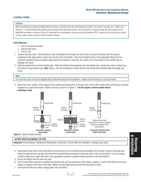
3. Mount the hook, weight, or the magnet to the welded end-plug section of the pipe (this is the bottom rigid section of the pipe) using the<br />
supplied nut, spacer and washer, tighten securely as shown in Figure 5. For the magnet, remove washer before<br />
installing in tank.<br />
Flexible pipe<br />
Flexible pipe<br />
Flexible pipe<br />
Welded<br />
end-plug<br />
Welded<br />
end-plug<br />
Welded<br />
end-plug<br />
Weight<br />
Nut<br />
Transmitter retention<br />
using weight<br />
Figure 5. Bottom fixing hardware<br />
Spacer<br />
Washer<br />
Magnet<br />
Remove<br />
washer<br />
Spacer<br />
Washer<br />
Nut<br />
Transmitter retention<br />
using magnet<br />
Bottom-fixing hook<br />
(mates with customer supplied<br />
hardware mounted in the<br />
tank bottom)<br />
Transmitter retention using<br />
bottom-fixing hook<br />
DO NOT DROP OR DAMAGE THE PIPE<br />
Important: Avoid kinking or bending the flexible pipe in less than 16 inch (406 mm) diameter or damage may result.<br />
4. Slide float(s) back down to the stop collar to prevent them from free falling during installation into the tank. Insert the flex pipe and<br />
floats through the tank riser pipe and lower the transmitter/float assembly into the tank until it rests on the bottom. If you are using<br />
a bottom-fixing hook, fasten the hook to the appropriate customer-supplied mating hardware at the tank bottom.<br />
5. Secure the flange onto the tank riser pipe.<br />
6. Pull the transmitter upward to straighten the flexible pipe until the resistance of the weight, magnet, or hook is felt without raising the<br />
weight or magnet off the floor of the tank. Tighten the adjustable fitting to hold the transmitter in place.<br />
7. Terminate the field wire cables noting proper wire orientation.<br />
<strong>Installation</strong> &<br />
Mounting<br />
<strong>MTS</strong> <strong>Sensors</strong><br />
11<br />
Level Plus ® Liquid-Level <strong>Sensors</strong> - M-Series <strong>Model</strong> <strong>MR</strong> Analog Transmitter<br />
Operation and <strong>Installation</strong> <strong>Manual</strong>, Document Number 550720 Revision G, 09/11 EN