Model MR Installation Manual - MTS Sensors
Model MR Installation Manual - MTS Sensors
Model MR Installation Manual - MTS Sensors

Create successful ePaper yourself
Turn your PDF publications into a flip-book with our unique Google optimized e-Paper software.
Electrical Connections<br />
& Wiring<br />
<strong>Model</strong> <strong>MR</strong> Operation and <strong>Installation</strong> <strong>Manual</strong><br />
Grounding and Safety Barriers<br />
Grounding<br />
Note:<br />
Grounding the transmitter through a threaded conduit connection does not provide sufficient ground.<br />
There are two methods to provide an earth ground to the earth ground of the electronics. Refer to’ Table 2’ for safety barrier references.<br />
• Run an earth ground through the conduit and connect directly to the earth ground lug inside the housing.<br />
• Run an earth ground directly to the ground lug on the outside of the housing.<br />
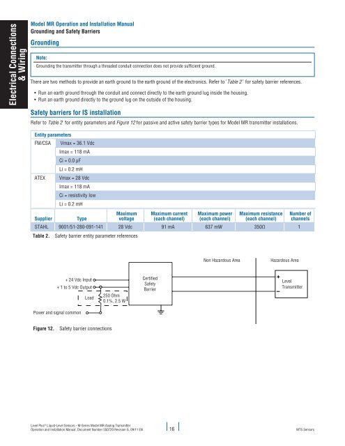
Safety barriers for IS installation<br />
Refer to Table 2 for entity parameters and Figure 12 for passive and active safety barrier types for <strong>Model</strong> <strong>MR</strong> transmitter installations.<br />
Entity parameters<br />
FM/CSA<br />
ATEX<br />
Supplier<br />
Vmax = 36.1 Vdc<br />
Imax = 118 mA<br />
Ci = 0.0 µF<br />
Li = 0.2 mH<br />
Vmax = 28 Vdc<br />
Imax = 118 mA<br />
Ci = resistivity low<br />
Li = 0.2 mH<br />
Type<br />
Maximum<br />
voltage<br />
Maximum current<br />
(each channel)<br />
Maximum power<br />
(each channel)<br />
Maximum resistance<br />
(each channel)<br />
STAHL 9001/51-280-091-141 28 Vdc 91 mA 637 mW 350Ω 1<br />
Table 2. Safety barrier entity parameter references<br />
Number of<br />
channels<br />
Non Hazardous Area<br />
Hazardous Area<br />
+ 24 Vdc Input Certified<br />
Level<br />
Safety<br />
+ 1 to 5 Vdc Output<br />
Transmitter<br />
Barrier<br />
Load<br />
250 Ohm<br />
0.1%, 2.5 W<br />
Power and signal common<br />
Figure 12. Safety barrier connections<br />
Non Hazardous Area<br />
Hazardous Area<br />
Certified<br />
Safety Bariers<br />
24 Vdc<br />
Supply-<br />
Voltage<br />
Transmitter 1<br />
I (A)<br />
4-20<br />
mA<br />
Level Plus ® Liquid-Level <strong>Sensors</strong> - M-Series <strong>Model</strong> <strong>MR</strong> Analog Transmitter<br />
Operation and <strong>Installation</strong> <strong>Manual</strong>, Document Number 550720 Revision G, 09/11 EN 16<br />
24 Vdc<br />
Supply-<br />
I.S. Ground connection<br />
Certified<br />
Safety Bariers<br />
Transmitter 2<br />
<strong>MTS</strong> <strong>Sensors</strong>