Model MR Installation Manual - MTS Sensors
Model MR Installation Manual - MTS Sensors
Model MR Installation Manual - MTS Sensors

Create successful ePaper yourself
Turn your PDF publications into a flip-book with our unique Google optimized e-Paper software.
Electrical Connections<br />
& Wiring<br />
<strong>Model</strong> <strong>MR</strong> Operation and <strong>Installation</strong> <strong>Manual</strong><br />
Electrical Connections, Wiring and Safety<br />
Electrical connections and wiring procedures<br />
A typical intrinsically safe connection for the Level Plus <strong>Model</strong> <strong>MR</strong> transmitter includes protective safety barriers, a power supply and a<br />
reading or monitoring device. Refer to Agency information for detailed information.<br />
A typical explosion proof connection for the <strong>Model</strong> <strong>MR</strong> transmitter includes a power supply and a reading or monitoring device connected<br />
using explosion proof conduit. Refer to Agency information for detailed information.<br />
Notes:<br />
For explosion proof installation, safety barriers are not required and wiring shall be installed in accordance with the National Electric Code ANSI/NFPA 70,<br />
Article 501-30 or the regional equivalent.<br />
Safety recommendations for installation<br />
Be sure to:<br />
1. Always follow applicable local and national electrical codes and observe polarity when making electrical connections.<br />
2. Never make electrical connections to the M-Series transmitter with power turned on.<br />
3. Make sure that no wire strands are loose or sticking out of the terminal block connection which could short and cause a problem.<br />
4. Make sure that no wire strands, including shield, are in contact with the electronic module enclosure.<br />
5. The electronics module enclosure is grounded through internal circuitry and is electronically isolated from the explosion-proof housing.<br />
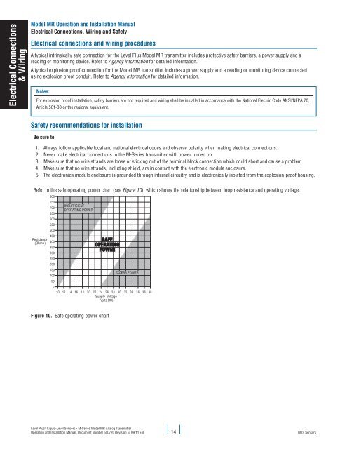
Refer to the safe operating power chart (see Figure 10), which shows the relationship between loop resistance and operating voltage.<br />
Resistance<br />
(Ohms)<br />
800<br />
750<br />
INSUFFICIENT<br />
700<br />
OPERATING POWER<br />
650<br />
600<br />
550<br />
500<br />
450<br />
400<br />
350<br />
300<br />
250<br />
200<br />
150<br />
EXCESS POWER<br />
100<br />
50<br />
0<br />
10 12 14 16 18 20 22 24 26 28 30 32 34 36 38 40<br />
Supply Voltage<br />
(Volts DC)<br />
Figure 10. Safe operating power chart<br />
Level Plus ® Liquid-Level <strong>Sensors</strong> - M-Series <strong>Model</strong> <strong>MR</strong> Analog Transmitter<br />
Operation and <strong>Installation</strong> <strong>Manual</strong>, Document Number 550720 Revision G, 09/11 EN 14<br />
<strong>MTS</strong> <strong>Sensors</strong>