Model MR Installation Manual - MTS Sensors
Model MR Installation Manual - MTS Sensors
Model MR Installation Manual - MTS Sensors

Create successful ePaper yourself
Turn your PDF publications into a flip-book with our unique Google optimized e-Paper software.
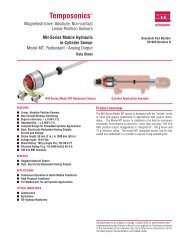
<strong>Model</strong> <strong>MR</strong> Operation and <strong>Installation</strong> <strong>Manual</strong><br />
Setup<br />
Quick start-up guide<br />
Before you begin<br />
Note:<br />
Output will vary depending on the location of the 4 and 20 mA set points.<br />
Tools Needed:<br />
• 24 Vdc linear regulated power supply<br />
• Current Meter<br />
Setup using keypad display<br />
Quick staRT-up procedure<br />
1. Connect 24 Vdc power supply<br />
2. Turn on power supply<br />
3. Connect Current Meter to test pins on the front of the puck<br />
4. Move the float to the tip of the pipe and verify 4 mA output<br />
5. Move the float to the top of the pipe and verify 20 mA output<br />
6. If using two floats, repeat steps 4 and 5 for second float<br />
7. Turn off power and disconnect power supply<br />
8. Install in tank<br />
9. Connect power and turn on<br />
Setup<br />
The <strong>Model</strong> <strong>MR</strong> transmitter can be calibrated by using the HART<br />
communications protocol or it may be manually calibrated using the<br />
optional keypad display. This section explains modes of operation<br />
and the steps you need to perform to calibrate your transmitter<br />
manually using the keypad display.<br />
Operation modes<br />
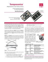
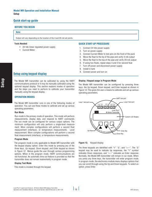
Display / Keypad usage in Program Mode<br />
The <strong>Model</strong> <strong>MR</strong> transmitter can be configured by pressing three<br />
keys, the Up keypad, Down keypad, and Enter keypad as shown in<br />
Figure 13. This gives the user a means to calibrate and set up various<br />
operating parameters.<br />
HART test port<br />
The <strong>Model</strong> <strong>MR</strong> transmitter runs in one of the following modes of<br />
operation. You can use these modes to calibrate and set up various<br />
operating parameters.<br />
Run Mode<br />
Run mode is the primary mode of operation. This mode will perform<br />
measurements, display data, and respond to HART commands.<br />
The run mode can be configured for various output options. The<br />
minimum configuration will only perform a single-level measurement.<br />
More complex configurations will perform a second float<br />
measurement (interface), or temperature measurements. Level<br />
measurement. More complex configurations will perform a second<br />
float measurement (interface), or temperature measurements.<br />
Program Mode<br />
The program mode is only applicable to <strong>Model</strong> <strong>MR</strong> transmitter with<br />
the keypad display option. Enter this mode by pressing any of the<br />
three keys, Up keypad, Down keypad, and Enter keypad as shown<br />
in Figure 12. Menus guide the user through various programming<br />
options. When in the program mode, HART communications are<br />
not functional. An automatic time out feature is provided so that the<br />
transmitter does not remain inadvertently in program mode.<br />
Display Test Mode<br />
This mode is invoked through the keypad.<br />
Loop 1 test port<br />
Up Key<br />
Loop 1 Test<br />
+ —<br />
TO REMOVE ELECTRONICS MODULE, PULLUNIT<br />
Figure 13. Keypad display<br />
HART<br />
Loop 2 Test<br />
+ —<br />
Level Plus ®<br />
M-Series Transmitter<br />
IN UPWARD DIRECTION - DO NOT TWIST ORTURN<br />
Down Key<br />
Loop 2 test port<br />
Enter Key<br />
Custom LCD Display<br />
The three keypads are identified with “∇” “∆”, and “