PCI8280 Telecom PCI Module Technical Reference Manual ... - NAT
PCI8280 Telecom PCI Module Technical Reference Manual ... - NAT
PCI8280 Telecom PCI Module Technical Reference Manual ... - NAT

Create successful ePaper yourself
Turn your PDF publications into a flip-book with our unique Google optimized e-Paper software.
<strong><strong>PCI</strong>8280</strong> – <strong>Technical</strong> <strong>Reference</strong> <strong>Manual</strong><br />
3.4 H.100 Bus Controller and Line Interfaces<br />
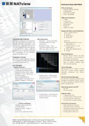
3.4.1 Block Diagramm of the TDM Structure<br />
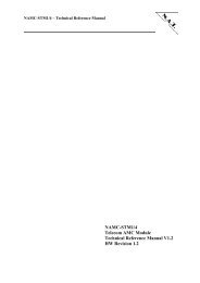
Figure 4: Local TDM Bus Organisation and Synchronisation<br />
MPC<br />
8265<br />
/<br />
MPC<br />
8280<br />
PA0<br />
LDO[0-7]<br />
LDI[0-7]<br />
LDI[0-3]<br />
L_CLK[0-1], L_FS[0-1]<br />
LDO[0-3]<br />
3.4.2 Description of the TDM Structure<br />
LREF[0-3]<br />
L_CLK[0], L_FS[0]<br />
OKI<br />
TSI<br />
Quad<br />
FALC<br />
The TDM data are routed through the ML53812-2 TSI device. Hence, any timeslot switching<br />
between H.110 bus, framers, and CPU is possible. Local TDM data lines LDI[0 – 3] and<br />
LDO[0 – 3] are routed between QuadFALC and TSI and CPU. In order to prevent data<br />
distortion the data outputs of the QuadFALC may be isolated from the TDM bus, if all 8<br />
TDM lines are to be used between TSI and CPU. The switch element connecting the<br />
QuadFALC data lines LDI[0 – 3] is enabled by programming CPU port pin PA0. Default:<br />
PA0 = 1, QuadFALC data lines LDI[0 – 3] enabled.<br />
The connection between the TDM data lines LDI[0 – 7] / LDO[0 – 7] and the corresponding<br />
TDM channels of the MPC8260 is shown in the following table:<br />
Version 1.2 © N.A.T. GmbH 17<br />
H.<br />
1<br />
1<br />
0<br />
L<br />
i<br />
n<br />
e