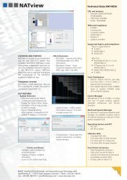
PCI8280 Telecom PCI Module Technical Reference Manual ... - NAT
PCI8280 Telecom PCI Module Technical Reference Manual ... - NAT
PCI8280 Telecom PCI Module Technical Reference Manual ... - NAT

You also want an ePaper? Increase the reach of your titles
YUMPU automatically turns print PDFs into web optimized ePapers that Google loves.
4.2.1.8 SDRAM Configuration Pins<br />
<strong><strong>PCI</strong>8280</strong> – <strong>Technical</strong> <strong>Reference</strong> <strong>Manual</strong><br />
DRTYPE0, Port pins used to set the correct multiplexing logic within Lattice U13.<br />
DRTYPE1 These pins code the size and array information of the SDRAM module<br />
installed. The correct binary value for DRTYPE1-0 has to be determined<br />
by reading the SDRAM SODIMM EEPROM contents. This EEPROM<br />
contains also further information needed to program the SDRAM controller<br />
of the MPC8280 appropriately, e.g. row start address and clock cycles<br />
needed for SDRAM access.<br />
DRTYPEx settings refer to following SODIMM organisation:<br />
Table 9: Supported SDRAM SODIMM <strong>Module</strong> Types<br />
DRTYPE1<br />
(PD22)<br />
DRTYPE0<br />
(PD23)<br />
highest<br />
column<br />
address to be<br />
multiplexed<br />
no. of<br />
SDRAM<br />
column<br />
addresses<br />
0 0 SDA7 8<br />
0 1 SDA8 9<br />
1 0 SDA9 10<br />
1 1 SDA11 11<br />
SDAx refers to SDRAM SODIMM address pin.<br />
Addresses to be programmed to be output on PowerQUICC II signals<br />
BNKSELx:<br />
Table 10: BNKSELx Programming<br />
DRTYPE1 DRTYPE0 BNKSEL2 BNKSEL1<br />
(PD22) (PD23)<br />
0 0 PB_A19 PB_A20<br />
0 1 PB_A18 PB_A19<br />
1 0 PB_A17 PB_A18<br />
1 1 PB_A16 PB_A17<br />
PB_Ax refers to PowerQUICC II address line Ax. BNKSEL0 is not used.<br />
Refer to chapter 6.3 of this manual and to the MPC8280 User’s <strong>Manual</strong> for<br />
a detailed description of how to program the Memory Controller of the<br />
MPC8280.<br />
Version 1.2 © N.A.T. GmbH 27