Catalog induSENSOR (PDF, 1.86 MB) - Micro-Epsilon
Catalog induSENSOR (PDF, 1.86 MB) - Micro-Epsilon
Catalog induSENSOR (PDF, 1.86 MB) - Micro-Epsilon

Create successful ePaper yourself
Turn your PDF publications into a flip-book with our unique Google optimized e-Paper software.
- 4 - Technology<br />
32 Technology and measuring principle<br />
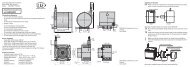
LVDT gauges and LVDT displacement sensors<br />
LVDT displacement sensors and gauges (Linear Variable Differential Transformer) are constructed<br />
with a primary and two secondary coils, which are arranged symmetrically to the primary winding.<br />
As a measurement object, a rod shaped magnetic core can be moved within the differential transformer.<br />
An electronic oscillator supplies the primary coil with an alternating current of constant<br />
frequency. The excitation is an alternating voltage with an amplitude of a few volts and a frequency<br />
between 1 and 10 kHz.<br />
Depending on the core position alternating voltages are induced in the two secondary windings.<br />
If the core is located in its “zero position“, the coupling of the primary to both secondary coils is<br />
equally large. Movement of the core within the magnetic field of the coil causes a higher voltage<br />
in one secondary coil and a lower voltage in the second coil. The difference between the two<br />
secondary voltages is proportional to the core displacement. Due to the differential design of the<br />
sensor, the LVDT series has an output signal which is very stable.<br />
Signal LVDT<br />
- Displacement<br />
100 %<br />
+ Signal<br />
100 %<br />
+ Displacement<br />
- Signal<br />
Gauging sensor<br />
Secondary coils<br />
Slide bearings<br />
Probe tip<br />
Linear measuring range<br />
Probe<br />
Magnetic core<br />
Primary coil<br />
Spring<br />
Displacement sensor<br />
Secondary coils<br />
Plunger<br />
Plunger<br />
Magnetic core<br />
Primary coil<br />
Core extension<br />
LDR displacement sensors<br />
The inductive sensors in the LDR series are constructed as half-bridge systems with centre tap.<br />
An unguided plunger moves in the interior of the sensor coil, which consists of symmetrically constructed<br />
winding compartments. The plunger is joined to the moving measurement object via a<br />
thread. Due to the movement of the plunger within the coil, an electrical signal is produced which<br />
is proportional to the displacement covered. The specific sensor configuration facilitates a short,<br />
compact design with a small diameter. Three connections are required as an interface to the sensor.<br />
Block diagram LDR series<br />
Target<br />
Measuring range<br />
Plunger<br />
Amplifier<br />
>><br />
Ue<br />
U / I a a