Manual capaNCDT 6300 / 6310 (PDF, 1.74 MB) - Micro-Epsilon
Manual capaNCDT 6300 / 6310 (PDF, 1.74 MB) - Micro-Epsilon
Manual capaNCDT 6300 / 6310 (PDF, 1.74 MB) - Micro-Epsilon
- No tags were found...

Create successful ePaper yourself
Turn your PDF publications into a flip-book with our unique Google optimized e-Paper software.
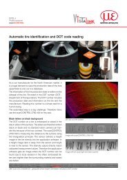
Safety1. SafetyKnowledge of the operating instructions is a prerequisite for equipment operation.1.1 Symbols UsedThe following symbols are used in this instruction manual:i1.2 WarningsIndicates a hazardous situation which, if not avoided, may result in minor or moderateinjury.Indicates a situation which, if not avoided, may lead to property damage.Indicates a user action.Indicates a user tip.Disconnect the power supply before touching the sensor surface.> > Danger of injury> > Static dischargeConnect the power supply and the display/output device in accordance with the safety regulations for electricalequipment.> > Danger of injury> > Damage to or destruction of the sensor and/or controllerAvoid shock and vibration the sensor and controller.> > Damage to or destruction of the sensor and/or controllerThe power supply may not exceed the specified limits.> > Damage to or destruction of the sensor and/or controller<strong>capaNCDT</strong> <strong>6300</strong> / <strong>6310</strong>Page 5
SafetyProtect the sensor cable against damage> > Destruction of the sensor> > Failure of the measuring device1.3 Notes on CE IdentificationThe following applies to the <strong>capaNCDT</strong> <strong>6300</strong>/<strong>6310</strong>: EMC regulation 2004/108/ECProducts which carry the CE mark satisfy the requirements of the EMC regulation 2004/108/EC ‘ElectromagneticCompatibility’ and the European standards (EN) listed therein.The EC declaration of conformity is kept available according to EC regulation, article 10 by the authoritiesresponsible atMICRO-EPSILON Messtechnik GmbH & Co. KGKönigbacher Straße 15D-94496 OrtenburgThe system is designed for use in industry and satisfies the requirements of the standards:--DIN EN 61326-1: 2006-10--DIN EN 61326-2-3: 2007-05The systems satisfy the requirements if they comply with the regulations described in the instruction manualfor installation and operation.1.4 Proper Use--The <strong>capaNCDT</strong> <strong>6300</strong>/<strong>6310</strong> measuring system is designed for use in industrial areas. It is used for• displacement, distance, thickness and movement measurement• position measuring of parts or machine components--The system may only be operated within the limits specified in the technical data, see Chap. 2.3.The system should only be used in such a way that in case of malfunction or failure personnel or machineryare not endangered.Additional precautions for safety and damage prevention must be taken for safety-related applications.<strong>capaNCDT</strong> <strong>6300</strong> / <strong>6310</strong>Page 6
Safety1.5 Proper Environment--Operating temperature:• Sensor:-50 ... +200 °C (-58 to +392 °F)• Sensor cable:-50 ... +150 C (-58 to +302 °F)• Controller, preamplifier: +10 ... +50 °C (-50 to +122 °F)--Humidity: 5 - 95 % (non condensing)--Ambient pressure: atmospheric pressure--EMC: according to DIN EN 61326-1: 2006-10DIN EN 61326-2-3: 2007-05--Storage temperature: 0 ... +75 °C (0 to +167 °F)--The space between the sensor surface and the target must have an unvarying dielectric constant.--The space between the sensor surface and the target may not be contaminated (for example water,rubbed-off parts, dust, et cetera)<strong>capaNCDT</strong> <strong>6300</strong> / <strong>6310</strong>Page 7
Functional Principle, Technical Data<strong>capaNCDT</strong> <strong>6300</strong> / <strong>6310</strong>2. Functional Principle, Technical Data2.1 Measuring PrincipleThe principle of capacitive distance measurement with the <strong>capaNCDT</strong> system is based on the principle of theparallel plate capacitor. For conductive targets, the sensor and the target opposite form the two plate electrodes.If a constant AC current flows through the sensor capacitor, the amplitude of the AC voltage at the sensor isproportional to the distance between the capacitor electrodes. The AC voltage is demodulated, amplified andoutput as an analog signal.The <strong>capaNCDT</strong> system evaluates the reactance X Cof the plate capacitor which changes strictly in proportionto the distance.1X c = ; capacitance C = * *jCr oiareadistanceA small target and bent (uneven) surfaces cause a non-linear characteristic.This theoretical relationship is realized almost ideally inpractice by designing the sensors as guard ring capacitors.The linear characteristic of the measuring signal isachieved for electrically conductive target materials(metals) without any additional electronic linearization.Slight changes in the conductivity or magnetic propertiesdo not affect the sensitivity or linearity.The <strong>capaNCDT</strong> system also measures reliably againstinsulating materials. The linear behavior for this categoryof targets is achieved by special electronic circuitry. Aconstant relative dielectric of the material is, however, aprerequisite for accurate measurement.GroundScreening electrodeMeasuring electrodeElectrical conductorFig. 1 Functional principle of the guard ringcapacitorPage 8
Functional Principle, Technical Data2.2 StructureThe non-contact, single-channel measuring system installed in an aluminum housing, consists of:--Sensor,--Sensor cable--Preamplifier (DT<strong>6310</strong> only)--Preamplifier cable (DT6319 only)--ControllerTwo versions with different kind of preamplifier are available:--DT<strong>6300</strong>: Controller with integrated preamplifier, distance sensor and controller: 1 m--DT<strong>6310</strong>: Controller with external preamplifier, distance sensor and controller: up to 20 mController: DT<strong>6300</strong>Controller: DT<strong>6310</strong>OscillatorOscillatorPower supplyIn-/OutputsSensorcableSensorPower supplyIN-/OutputsPreamplifierPreamplifiercableDemodulatorPreamplifierDemodulatorSensorcableSensorPower supply PS300/15Power supply PS300/15Fig. 2 Block diagram <strong>capaNCDT</strong> <strong>6300</strong> Fig. 3 Block diagram <strong>capaNCDT</strong> <strong>6310</strong><strong>capaNCDT</strong> <strong>6300</strong> / <strong>6310</strong>Page 9
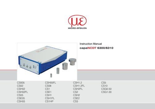
Functional Principle, Technical Data<strong>capaNCDT</strong> <strong>6300</strong> / <strong>6310</strong>2.2.1 SensorsFor this measurement system, several sensors can be used.In order to obtain accurate measuring results, keep the surface of the sensor clean and free from damage.The capacitive measuring process is area-related. A minimum area (see table) is required depending on thesensor model and measuring range. In the case of insulators the dielectric constant and the target thicknessalso play an important role.Sensors for electrical conducting targets (metals)Sensor model Measuring range Min. target diameterCS005 0.05 mm 3 mmCS02 0.2 mm 5 mmCSH02 0.2 mm 7 mmCSH02FL 0.2 mm 7 mmCS05 0.5 mm 7 mmCSE05 0.5 mm 6 mmCSH05 0.5 mm 7 mmCSH05FL 0.5 mm 7 mmCS08 0.8 mm 9 mmCS1 1 mm 9 mmCSE1 1 mm 8 mmCSH1 1 mm 11 mmCSH1FL 1 mm 11 mmCS1HP 1 mm 9 mmCSH1.2 1.2 mm 11 mmCSH1.2FL 1.2 mm 11 mmCSH2FL 2 mm 17 mmCS2 2 mm 17 mmCSH2 2 mm 17 mmCSE2 2 mm 14 mmCS3 3 mm 27 mmPage 10
Functional Principle, Technical DataCS5 5 mm 37 mmCS10 10 mm 57 mmCSG0.50 0.5 mm ca. 7 x 8 mmCSG1.00 1.00 mm ca. 8 x 9 mmSensors for insulating targets materials.The sensors also measure reliable against insulating materials. The linear behavior for this category of targetsis achieved by special linearization, see Chap. 5.4. The measuring ranges of the respective sensors dependon the e rof the target.<strong>capaNCDT</strong> <strong>6300</strong> / <strong>6310</strong>Page 11
Functional Principle, Technical Data2.2.2 Sensor CableThe sensor and controller respectively sensor and preamplifier are connected by a special, double screened,1 m (3 ft) long sensor cable.Do not shorten or lengthen these special cables.Usually, a damaged cable can not be repaired.Switch off the device when plugging and removing connectors.i Do not crush the sensor cable.Do not modify to the sensor cable.The sensors of type CSH have integrated a 1.4 long sensor cable. Cable lengths of 2.8 m are available too ifrequired.Model Cable length 2 axial connector 1x axial + 1x 90 ° For sensors Minimum bending radius:CC1C 1 m x 0.05 - 0.8 mmCC2C 2 m x 0.05 - 0.8 mm 10 mm (once)CC3C 3 m x 0.05 - 0.8 mm 38 mm (permanently)CC4C 4 m x 0.05 - 0.8 mmCC1C/90 1 m x 0.05 - 0.8 mmCC2C/90 2 m x 0.05 - 0.8 mmCC3C/90 3 m x 0.05 - 0.8 mmCC4C/90 4 m x 0.05 - 0.8 mmCC1B 1 m x 1 ... 10 mmCC2B 2 m x 1 ... 10 mmCC3B 3 m x 1 ... 10 mmCC4B 4 m x 1 ... 10 mmCC1B/90 1 m x 1 ... 10 mmCC2B/90 2 m x 1 ... 10 mmCC3B/90 3 m x 1 ... 10 mmCC4B/90 4 m x 1 ... 10 mm<strong>capaNCDT</strong> <strong>6300</strong> / <strong>6310</strong>Page 12
Functional Principle, Technical Data2.2.3 Preamplifier (DT<strong>6310</strong> only)The preamplifier is necessary as connector between sensor and controller. With this preamplifier it is possibleto deal with greater distances between sensor and controller. The sensor cable length is fixed at1 m (4 m with additional adjustment of the controller) and must not be modified by the user.Fig. 4 Preamplifier CP60012.2.4 Preamplifier Cable (DT<strong>6310</strong> only)The cable carriers capable preamplifier cable connect the preamplifier with the controller. It is possible tohandle a distance of up to 20 m.The user may not shorten or lengthen these special cables. Usually, a damaged cable can not be repaired.Model Cable length Min. bending radius, permanentCA5 5 mCA10 10 mCA20 20 m33 mmCA25 25 m<strong>capaNCDT</strong> <strong>6300</strong> / <strong>6310</strong>Page 13
Functional Principle, Technical Data2.2.5 ControllerThe controller principally consists of an oscillator- and a demodulator unit. Both are stored in an aluminumhousing.POWER IN SENSOR/CP SIGNAL OUT POWER/SYNCSTATUSZERO LIN GAINRANGEZEROFig. 5 Front view DT<strong>6300</strong>/<strong>6310</strong>Fig. 6 Rear view DT<strong>6300</strong>/<strong>6310</strong>OscillatorThe oscillator supplies the sensor with constant frequency and amplitude-stable alternating current. Thefrequency is 31 kHz.DemodulatorDemodulation, linearization and amplifying of the distance-dependent measuring signal are tasks of the demodulatorunit. The three trim-pots, see Fig. 5, allow a special--Linearity--Gain--Zeroadjustment of the complete measuring channel, see Chap. 5.3, see Chap. 5.4.Output voltage can achieve up to 14 VDC, if the sensor is disconnected respectively exceedance ofmeasuring range.i<strong>capaNCDT</strong> <strong>6300</strong> / <strong>6310</strong>Page 14
Functional Principle, Technical Data2.3 Technical DataController typeResolution staticResolution dynamicLimit frequencyLimit frequency adjustableLinearityMax. sensitivity deviationLong term stabilitySynchronous operationInsulator measurementFSO = Full Scale Output<strong>capaNCDT</strong> <strong>6300</strong> / <strong>6310</strong>DT<strong>6300</strong>/DT<strong>6310</strong>0.001 % FSO0.01 % FSO (8 kHz)8 kHz20 Hz / 1 kHz / 8 kHz±0.2 % FSO (all sensors interchangeable without calibration)Option LC: ±0.1 % FSO (tuned to one sensor)±0.1 % FSO≤ 0.02 % FSO / monthTemperature stability ±0.01 % FSO / °CTemperature range (operation) +10 … +50 °CTemperature range (storage) -10 … +75 °CSupplyOutputSuitable for sensorsSensor cable standardSensor cable (matched)Proper environment sensorProtection classyesyes±15 VDC (±2 %) / ±150 mA0 - 10 VDC (max. 10 mA short circuit proof)4 ... 20 mA (load max. 500 Ω)all sensors≤ 1 mup to 4 mHumidity 5 to 95 % (non condensing)IP 54 (Controller and sensors)Electromagnetic compatibility (EMC) DIN EN 61326-1: 2006-10 and DIN EN 61326-2-3: 2007-5Page 15
Delivery3. Delivery3.1 Unpacking 3.2 Storage1 Controller Storage temperature: 0 °C up to +75 °C (+32 °F to +167 °F)1 Plug (if PC3/8 was not ordered)Humidity:0 - 95 % RH (non condensing)+ 1 plug for 4-pole signal output1 Instruction manualOptional accessories, separately packed:1 Sensor 1 Preamplifier (DT<strong>6310</strong> only)1 Sensor cable with plug 1 Preamplifier cable (DT<strong>6310</strong> only)1 Power and output cable PC3/8Remove the parts of the system carefully from the packaging and transport them in such a way that theyare not damaged.Check for completeness and shipping damages immediately after unpacking. In case of damage ormissing parts, please contact the manufacturer or supplier.<strong>capaNCDT</strong> <strong>6300</strong> / <strong>6310</strong>Page 16
Installation and Assembly4. Installation and Assembly4.1 Precautionary MeasuresNo sharp-edged or heavy objects may get into contact with the sensor cable sheath.iProtect the cable against pressure loads in pressurised rooms.Avoid kinks in any case.Check the connections for tight fit.A damaged cable cannot be repaired.4.2 SensorThe sensors may be mounted free-standing or flush.When assembling, make sure that the polished sensor surface is not scratched.4.2.1 Radial Point Clamping with Grub Screw, Cylindric SensorsThis simple type of fixture is only recommended for a force and vibration-free installation position. The grubscrew must be made of plastic so that it cannot damage or deform the sensor housing.Grub screwFig. 7 Radial point clamping with grub screwDo not use metal grub screws!> > Danger of damaging the sensor<strong>capaNCDT</strong> <strong>6300</strong> / <strong>6310</strong>Page 17
Installation and Assembly4.2.2 Circumferential Clamping, Cylindric SensorsThis sensor mounting option offers maximum reliability because the sensor is clamped around its cylindricalhousing. It is absolutely necessary in difficult installation environments, for example on machines, productionplants et cetera.Mounting withclamping ringFig. 8 Circumferential clampingiTension at the cable is inadmissible!4.2.3 Flat SensorsFlat sensors are mounted by means of a tap hole for M2 (in case of sensors 0.2 and 0.5 mm) or by a throughhole for M2 screws. The sensors can be bolted on top or below.Screwing from aboveScrewing from bottom<strong>capaNCDT</strong> <strong>6300</strong> / <strong>6310</strong>Page 18
Installation and Assembly4.2.4 Dimensional Drawings SensorsCS005ø3 (0.118 dia.)8 1 (.315)11 (.433)ø6f7 (.236 dia.)12(.472)Connector sideCS2M=1:2ø20h7 (.79 dia.)20 1 (.787)CS028 1 (.315)ø6f7 (.236 dia.)24 -0.2(.945) -0.08CS3M=1:2Connector side12(.472)ø30h7 (1.18 dia.)16.5 1 ( .649)ø20h7 (.79 dia.)CS058 1 (.315)12(.472)ø8f7 (.314 dia.)24 -0,2(.945) -0.08CS5M=1:2ø40h7 (1.58 dia.)CS0815 (.590)ø10f7 (.394 dia.)16.5 1 ( .649)ø20h7 (.79 dia.)24 -0,2(.945) -0.081) Adjustment area for radial point respectively circumferential clampingCS1HP15 1 (.590)20 -0,2(.787 -008 )ø10f7 (.394 dia.)M=1:2CS10ø60h7 (2.36 dia.)ø20h7 (.79 dia.)CS121 -0 2(.826 -008 )17 1 (.669)ø10f7 (.394 dia.)16.5 124 -0,2Dimension6e76h66f78f710f720h730h740h760h7Fittolerance-20-320-8-1022-13-28-13-280-210-210-250-30<strong>capaNCDT</strong> <strong>6300</strong> / <strong>6310</strong>1 µm = 0.001 mm= 1 micronPage 19
Installation and AssemblyCSE059 (.35)12 (.47)ø5.7 (.22)ø6f7(.24 dia.)CSE1ø8f7 (0.31 dia.)ø7.7 (0.30 dia.)9 (0.35)12 (0.47)CSE2ø14h7 (0.55 dia.)ø13.7 (0.54 dia.)18.5 (0.73)22 (0.87)Connector sideCSG0.50-CAm2.0 and CSG1.00-CAm2.020.2 (0.80)Sensor structuresThickness 0.9 -0.05 (0.04 -0.002 ) Sensor structures200 (7.87)216 (8.5)9.9 (0.39)1 (0.04)15(0.59)R24.2 (0.17)2.9(0.11)5.4(0.21)4.5(0.18)4.2 (0.17)6.2 (0.24)4.4(0.17)3.85(0.15)CSG0.50-CAm2.0 CSG1.00-CAm2.0 Dimensions in mm (inches), not to scale<strong>capaNCDT</strong> <strong>6300</strong> / <strong>6310</strong>Page 20
Installation and AssemblyCSH02, CSH05ø8g6 (.315 dia.)ca. 9.4 (.37)CSH1, CSH1.2ø12g6 (.473 dia.)ca. 9.4 (.37)10 1 (.39)14(.39)ø7.5(.30 dia.)33(1.30)ca. 37 (1.46)10 1 (.39)14(.39)ø11.5(.45 dia.)33(1.30)ca. 37 (1.46)ø2.2 (.09 dia.)ø2.2 (.09 dia.)Dimensions in mm (inches), not to scale1) Adjustment area for radial point respectively circumferential clamping<strong>capaNCDT</strong> <strong>6300</strong> / <strong>6310</strong>Page 21
Installation and Assembly33 (1.3)CSH2ø20g6(0.79 g6 dia.)ca. 9.4 (.37)Clamparea10(.39)14(.55)ø19.5(.77 dia.)ca. 37 (appr. 1.46)ø2.2(.09 dia)Dimensions in mm (inches), not to scale<strong>capaNCDT</strong> <strong>6300</strong> / <strong>6310</strong>Page 22
Installation and AssemblyCSH02FL, CSH05FL4 (.16)0.1 (.003)3.5(.14)4(.16)ø3(.12 dia.)M2R4 (.16)1.75(.07)5.5(.22)6.5(.25)ca. 9.4 (.37)ca. 37 (1.46)ø4(.16 dia.)CSH1FL, CSH1.2FL4 (.16)0.1(.003)4.5(.18)5(.20)ø2.5(.10)ø3(.12 dia.)R6(.24)2.25(.09)7.5(.29)11 (.43)ca. 9.4 (.37)ca. 37 (1.46)ø2.2(.09 dia.)ø2.2(.09 dia.)Dimensions in mm (inches), not to scale<strong>capaNCDT</strong> <strong>6300</strong> / <strong>6310</strong>Page 23
Installation and Assembly5 (.20)1.6 (.06)ø4 (.16 dia)ø2.2(.09 dia)0.1(.004)7.6 (.30)CSH2FL20 (.79)15.5 (.61)15.5 (.61)20 (.79)ø3(.12 dia.)ca. 9.4 (.37)ca. 37 (1.46)ø2.2(0.09 dia.)Dimensions in mm (inches), not to scale<strong>capaNCDT</strong> <strong>6300</strong> / <strong>6310</strong>Page 24
Installation and Assembly4.3 Sensor CableThe sensor is connected to the controller by the sensor cable. The connection is made by simple plugging.The connector locks automatically. The tight fit can be checked by pulling the connector housing (cablebushing). The lock can be released and the connector can be opened by pulling the knurled housing sleeveof the cable bushing.Ø5.4 (.21)Ø6 (.24)8.6 (.34)13.7 (.54)17.5 (.69)Sensor cable CCxCØ3.2Cable length x27 (1.06)37 (1.46)Ø7 (.28)Ø9.6 (.38)16.9 (.67)Sensor cable CCxC/9016 (10.08)8 (.31)13.1(.52)Ø6 (.24)Ø5.4 (.21)Sensor cable CCxBØ3.2(.13)Cable length x27 (1.06)37 (1.46)Ø7 (.28)Ø9.5 (.37)20.5 (.81)30.5 (1.20)Sensor cable CCxB/9025 (.98)<strong>capaNCDT</strong> <strong>6300</strong> / <strong>6310</strong>Dimensions in mm (inches), not to scaleMinimum bending radius: 10 mm (once) X = 1 or 4 m38 mm (permanently)Model 2 axial connectors 1x axial + 1x 90 ° for sensorsCCxC • < 1 mmCCxC/90 • < 1 mmCCxB • ≥ 1 mmCCxB/90 • ≥ 1 mmØ7 (.28)Ø10 (.39)Page 25
Installation and Assembly4.4 Preamplifier CP600134.6(1.36)8 (.36)4.5 (.18)114 (4.49)53)73 (2.87)42 (1.65)85.6 (3.37)Sensor ControllerFig. 9 Preamplifier CP6001, dimensions in mm, not to scaleMounting preamplifier with mounting device (CP6001)Remove the four black protecting caps at the housing screws, dimension 73.Remove the four housing screws.Fix the both mounting devices at the preamplifier. Use the screws contained in the delivery.<strong>capaNCDT</strong> <strong>6300</strong> / <strong>6310</strong>Page 26
Installation and Assembly19.3( 8)7(.3)2.5 (.1) x 45°ø3.2 (.13)R2 ( 08)25 (1.0)2(.08)61.4 (2.4) 15( 6)73 (2.9)84.6 (3.3)8.5(.34)4.2(.16)ø4.2(.16)5.8 (.23)9.8 (.38)78.8 (3.1)Fig. 10 Mounting device for preamplifier, dimensions in mm, not to scale<strong>capaNCDT</strong> <strong>6300</strong> / <strong>6310</strong>Page 27
Installation and Assembly4.5 Preamplifier CableØ 8.9 (.35 dia.)x = cable length 5 ... 25 m (standard 5 m)~35~25SW8Ø 4.3±3 mm(.19 dia.)Dimensions in mm Inches), not to scaleModel Cable length Min. bending radius, permanentCA5 5 mCA10 10 mCA20 20 m33 mCA25 25 m<strong>capaNCDT</strong> <strong>6300</strong> / <strong>6310</strong>Page 28
Installation and Assembly4.6 Controller44.7 (1.76) 13(.51)175 (6.89)155 ((6.10)4(.16)POWER N SENSOR/CP SIGNAL OUT POWER/SYNC4x Mounting holes forscrews M4 x 45 (min.)97 (3.82)110 (4.33)ø4.6 (.18)ø8 (.32)Dimensions in mm (inches), not to scale<strong>capaNCDT</strong> <strong>6300</strong> / <strong>6310</strong>Page 29
Installation and Assembly4.7 Ground Connection, EarthingMake sure you have a sufficient grounding of the measuring object, for example connect it with the sensoror the supply ground.Non-contact target earthingIn several applications, the target earthing is difficult or even impossible.Different to other systems, with <strong>capaNCDT</strong> systems is no target earthing necessary.Two synchronized <strong>capaNCDT</strong> sensors, measuring against a mill, are shown, see Fig. 11. Due to the uniquesynchronizing technique of <strong>Micro</strong>-<strong>Epsilon</strong> in most cases a special target earthing is not needed.SensorSensorControllersync.ControllerNo target grounding requiredwith two <strong>capaNCDT</strong> sensors!Fig. 11 Position and unbalance measurement with two systems4.8 Power Supply, the Display/Output Device and SynchronizationThe power supply and the signal output are located at the backside of the controller. Regarding jacks andplugs for the cable are included in the standard scope of delivery for customized cable assembling.Furthermore, several controller DT<strong>6300</strong>/<strong>6310</strong> can be synchronized and supplied with the PSCC30.In this case, use the cable SCAC3/4 for signal output only.<strong>capaNCDT</strong> <strong>6300</strong> / <strong>6310</strong>Page 30
Installation and AssemblySensorCP6001(<strong>capaNCDT</strong><strong>6310</strong>)Externaldisplayz.B. CC1Bz.B. CA5SCAC3/4POWER IN SENSOR/CP SIGNAL OUT POWER/SYNC POWER IN SENSOR/CP SIGNAL OUT POWER/SYNCPC3/8PS100/230/15±15 VDC/500 mAPSCC30Fig. 12 System assembly and synchronization with a second controllerSynchronization in multi-channel modeSeveral measuring systems <strong>capaNCDT</strong> <strong>6300</strong>/<strong>6310</strong> can simultaneously be used as multi-channel system. Withthe synchronization of the systems, a mutual influence to the sensors is avoided:Plug the synchronize cable PSCC30 (accessory) into the jack POWER/SYNC at controller 1.Plug the second end of PSCC30 into the jack POWER IN at the second controller.--The oscillator of controller 2 switches automatically into sychronization, this means, depending on theoscillator of controller 1.--An influence of poor earthed target is excepted.Where necessary, synchronize more measuring systems with the cable PSCC30.iAutomatic synchronization. Every controller can be master.<strong>capaNCDT</strong> <strong>6300</strong> / <strong>6310</strong>Page 31
Installation and Assembly4.9 Pin AssignmentPin AssignmentColor PC 3/8Inner cable Outer cable1 Sync In white2 +15 VDC brown3 U OUT, (Load min. 10 kOhm) green4 -15 VDC yellow5 Supply ground grey6 NC green7 Analog ground blue8 I OUT, (Load max. 500 Ohm) red1) In addition the following should be noted when assembling theuser-side connecting cable:- Use a double screened cable!- Outer screening mesh surrounds all cable wires- Inner screening mesh surrounds signal wires PIN 3, 7, 8- Inner screening mesh at pin 7Total screen via connector housing to housing ground- Recommended conductor cross-section 0.14 mm 2The EMC regulations, see Chap. 1.3, are only satisfied if these basicconditions have been observed.PC3/8 1 is a 3 m (9.84 ft) long, preassembled8-wire power supply andoutput cable. It is supplied as anoptional accessory.POWER IN SENSOR/CP SIGNAL OUT POWER/SYNCFig. 13 Power supply input at controller,8-wire DIN-plug (DIN 45326)- black: outer screen- bare: inner screen (connect withPin 7, blue)6 78134 52View on solder pin side, 8-pole DINfemale cable connector<strong>capaNCDT</strong> <strong>6300</strong> / <strong>6310</strong>Page 32
Installation and AssemblyPin AssignmentConductor colorSCAC 3/41 U OUT, (Load min. 10 kOhm) brown2 I OUT, (Load max. 500 Ohm) yellow3 Analog ground grey4 Analog ground whiteAnalog ground connected internally.SCAC3/4 is a 3 m (9.84 ft) long, pre-assembled 4-wiremulti-channel output cable. It is supplied as an optionalaccessory.POWER N SENSOR/CP SIGNAL OUT POWER/SYNCFig. 14 Signal output at the controller, 4-wire plugU OUTI OUTAGNDAGNDView on solder pin side, 4-pole male cable connector<strong>capaNCDT</strong> <strong>6300</strong> / <strong>6310</strong>Page 33
Installation and AssemblyPin AssignmentWire color PSCC 30Inner cable Outer cable1 Sync OUT white2 +15 VDC brown3 NC green4 -15 VDC yellow5 Supply ground green6 NC green7 Analog ground blue8 NC redPSCC 30 is a 0,3 m (0.98 ft) long, pre-assembledpower and synchronization cable.It is supplied as an optional accessory.POWER IN SENSOR/CP SIGNAL OUT POWER/SYNCFig. 15 Outputs for synchronization, 8-poleDIN-jack (DIN 45326)37861View on solder pinside, 8-pole DINmale cable connector5246 78134 52View on solder pinside, 8-pole DINfemale cable connector<strong>capaNCDT</strong> <strong>6300</strong> / <strong>6310</strong>Page 34
Operation5. Operation5.1 Starting UpConnect the the display/output devices through the signal output socket, see Chap. 4.8, see Chap. 4.9,before connecting the device to the power supply and switching on the power supply.Allow the measuring system to warm up before the first measurement or calibration:i DT <strong>6300</strong>: ca. 10 min.DT <strong>6310</strong>: ca. 30 min.5.2 Basic SettingsThe gain, zero and linearity point of the measuring channel are adjusted with the ’GAIN’, ’ZERO’ and ’LIN’trimmer potentiometers, see Fig. 16, (the setting range is approximately 15 turns per potentiometer).The end settings at the left and right stops are recognizable by a slight click.LED Color FunctionZero point Linearity AmplificationController failureSTATUSorange Controller OK<strong>capaNCDT</strong> <strong>6300</strong> / <strong>6310</strong>ZERO LIN GAINSTATUSRANGEZERORANGEZEROFig. 16 Control elements at the controllerDisconnect the power supply before touching the sensor surface.> > Static discharge> > Danger of injuryThe potentiometer are ex works at the right stop (maximum level).greenredredTarget in measuring rangeTarget out of measuring rangeFactory settingController operates with changedfactory settingPage 35
OperationTrimmer SettingZero: Shifts the output signal in negative direction to left.Lin: Reduce the quadrate component by turning the trimmer to left.Gain: Reduce the characteristic line slope by turning the trimmer to left.Lin and Gain only are active by insulating measurement.Position 1Choice of targetChoose with a slide switch, see Fig. 17, between conductingand nonconducting target.In position 2 zero point setting with the zero trim-pot is activeonly. Gain is set to 0 up to 10 V through the whole measuringrange.Position 1 (Insulator), non-conductingPosition 2Position 2 (Metal), conductingFig. 17 Electronics in the controller<strong>capaNCDT</strong> <strong>6300</strong> / <strong>6310</strong>Page 36
Operation5.3 Calibration with Metal TargetsPreconditions:--Specific resistance of the target < 1 kΩcm.--Slide switch on the demodulator in position 2 (metals, see Fig. 17).For metallic targets the demodulator´s linearization function is switched off since a linear characteristic isalready available automatically on account of the measuring principle and sensor construction.The measuring device is set to a sensitivity of 10 Volts corresponding to the measuring range of each sensormodel.The electrical zero point can be set across the whole measuring range with the .zero. potentiometer of thedemodulator module. The start of the measuring range (= mechanical zero point) is on the front face of thesensor.A tilted sensor or measuring object results in a reduced measuring range and zero point shifting according tothe tilting.Curved target surfaces cause linearity reductions if the distance between the sensor and the target is small.Also with small target surfaces losses in linearity and sensibility occur.Extension of the measuring range:The sensor measuring ranges by metal measurement can be extended considerably (by a factor of 2-3) withsome loss in linearity and sensitivity.To do this, move the slide switch on the demodulator board to position 1.Make the necessary linearity adjustment, see Chap. 5.4.In step 1 here the following potentiometer setting is assumed:--zero: right stop--gain: left stop--linearity: right stopCarry out the complete calibration up to step 4.<strong>capaNCDT</strong> <strong>6300</strong> / <strong>6310</strong>Page 37
Operation5.4 Linearity Adjustment and Calibration with Insulator TargetsPreconditions:--Specific resistance of the target > 10 6 Ωcm.--Slide switch on the demodulator in position 1The measuring channel must be individually linearized and calibrated prior to measurements against insulatortargets. Adjustment takes place at defined distances which are prescribed by a reference. A specialmicrometer calibration device with a non-rotating micrometer spindle (for example MC25 from MICRO-EPSI-LON) has proved to be particularly suitable. Spacer discs are not suitable.The following parameters influence the calibration. Later operating conditions should be simulated as accuratelyas possible for the calibration. If one of these parameter changes, recalibration is recommended:--Resistivity of the target--Dielectric constant of the target--Shape and thickness of the insulator--With thin targets, metal behind the target may influence the propagation of the field lines.The greater the relative dielectric constant, the higher is the sensitivity of the measurement system.Step 1:Settings: .zero. right stop, .gain. middle, .linearity. middleRecord the measuring curve of the sensor at least10 points.Choose a range of low and as constant as possiblecurvature from this curve and determine the points:- A Start of measuring range- B Centre of measuring range- C End of measuring rangeThe output signal at point C should not exceed 10 V in thechosen measuring range. If necessary, the sensitivity canbe reduced with the .gain. potentiometer.SignalCC-BBC-AB-AADisplacementFig. 18 Define the active measuring range<strong>capaNCDT</strong> <strong>6300</strong> / <strong>6310</strong>Page 38
OperationStep 2: LinearityThe measured value differences B-A and C-B are calculated from the fixed measuring points A B C andcompared with each other. The setting of the .linearity. potentiometer is now altered until B-A and C-B areidentical.If the setting is not valid, you can do the following:Add with the trimmer .linearity. a quadratic component to the characteristic, which compensates thephysical not linear element of insulators.In position zero (left stop) no quadratic component is added.If the value C exceeds 10 V reduce the sensitivity (.gain.).If the .linearity. potentiometer is at the stop and B-A and C-B are still not equal, points A and C have probablybeen badly chosen.Start again with step 1.Step 3: SensitivityIn order to set a practicable sensitivity, first form the signal difference C-A and select a sensitivity whichmatches the measuring range (for example 1 V/mm).Calculate the required measured value C’ and set the distance point C.C’ = C E(C - A)E ... desired signal span point A to CC ... signal value at distance point CA ... signal value at distance point AIf C’ is not more than 10 V, set it with the .gain. potentiometer.As a final check, run through the whole measuring curve and document it.<strong>capaNCDT</strong> <strong>6300</strong> / <strong>6310</strong>Page 39
OperationStep 4: Zero pointThe electrical zero point can now be shifted without affectingthe linearity and sensitivity.1/1Signal00 0.51/1Measuring rangeSensorTargetFig. 19 Signal behavior of the output voltage5.5 Changing Limit FrequencyThe controller operates with a limit frequency of 8 kHz (factory setting). In the case that the limit frequencyis reduced, the output signal is filtered more efficiently and the resolution is therefore improved. At the sametime the dynamic of the system is reduced.Procedure for changing the limit frequency:Open the controller.Set the requested limit frequency usingthe micro-switch, see Fig. 20.Close the controller.<strong>capaNCDT</strong> <strong>6300</strong> / <strong>6310</strong>Fig. 20 Limit frequencyPage 40
Measurement6. MeasurementWith the <strong>capaNCDT</strong> either the deflection or the compensation method of measurement can be applied.--Deflection method for fast events, tolerance monitoring and for insulators:Put the zero point in the centre of the measuring range, the output signal is then in proportion to the distance.Fast events are displayed on a suitable external recorder (oscilloscope, recorder, transient recorder).--Compensation method for constant or slowly changing distances.Compensation is carried out with the .zero. potentiometer until the output signal is 0 Volt. Sensitivity is notaffected by doing this.7. Operation and MaintenancePlease take care of the following:Make sure that the sensor surface is always clean.Switch off the power supply before cleaning.Clean with a damp cloth; then rub the sensor surface dry.Changing the target or very long operating times can lead to slight reductions in the operating quality (longterm errors). These can be eliminated by recalibration, see Chap. 5.3, see Chap. 5.4.Disconnect the power supply before touching the sensor surface.> > Static discharge> > Danger of injuryIn the event of a defect in the controller, the sensor or the sensor cable, the parts concerned must be sentback for repair or replacement. In the case of faults the cause of which is not clearly identifiable, the wholemeasuring system must be sent back for repair or replacement toMICRO-EPSILON MESSTECHNIK GmbH & Co. KGKönigbacher Straße 1594496 Ortenburg<strong>capaNCDT</strong> <strong>6300</strong> / <strong>6310</strong>Page 41
Warranty8. WarrantyAll components of the device have been checked and tested for perfect function in the factory. In the unlikelyevent that errors should occur despite our thorough quality control, this should be reported immediately to<strong>Micro</strong>-<strong>Epsilon</strong>.The warranty period lasts 12 months following the day of shipment. Defective parts, except wear parts, will berepaired or replaced free of charge within this period if you return the device free of cost to <strong>Micro</strong>-<strong>Epsilon</strong>.This warranty does not apply to damage resulting from abuse of the equipment and devices, from forcefulhandling or installation of the devices or from repair or modifications performed by third parties.No other claims, except as warranted, are accepted.<strong>Micro</strong>-<strong>Epsilon</strong> will specifically not be responsible for eventual consequential damage. The terms of the purchasingcontract apply in full.<strong>Micro</strong>-<strong>Epsilon</strong> always strives to supply the customers with the finest and most advanced equipment.Development and refinement is therefore performed continuously and the right to design changes withoutprior notice is accordingly reserved.For translations in other languages, the data and statements in the German language operation manual areto be taken as authoritative.9. Decommissioning, DisposalDisconnect the cable for electrical power and output signal on the controller.Disconnect the cable between sensor and controller.The <strong>capaNCDT</strong> <strong>6300</strong>/<strong>6310</strong> is produced according to the directive 2002/95/EC („RoHS“).Do the disposal according to the legal regulations (see directive 2002/96/EC).<strong>capaNCDT</strong> <strong>6300</strong> / <strong>6310</strong>Page 42
Accessories, Service10. Accessories, ServiceAccessoriesMC2.5 <strong>Micro</strong>meter calibration fixture, range 0-2.5 mm / 0-0.1 inch, division 1 µmfor sensors CS005 ... CS2MC25DPC3/8CSP 301SCAC3/4PSCC30SWHDigital micrometer calibration fixture,Range 0-25 mm / 0-1 inch,adjustable offset (zero), for all sensorsPower and output cable, 3 m (9.84 ft) length, 8-wireDigital signal processing unit with display for synchronous processing of two channelsOutput cable for multi-channel operation necessarySupply- / synchronization cable for multi-channel operation necessaryVacuum feed through34 (1.34)2 (.08)SW12ø8.8 (.35)M10x0.75ø14(.55 dia.)9(.35)max. 17(.67)Dimensions in mm (inches), not to scaleServiceFunction and linearity check-out, inclusive 11-point protocol with graphic and post-calibration.<strong>capaNCDT</strong> <strong>6300</strong> / <strong>6310</strong>Page 43
MICRO-EPSILON MESSTECHNIK GmbH & Co. KGKönigbacher Str. 15 · 94496 Ortenburg / GermanyTel. +49 (0) 8542 / 168-0 · Fax +49 (0) 8542 / 168-90info@micro-epsilon.de · www.micro-epsilon.comX9751161-A061063HDRMICRO-EPSILON MESSTECHNIK*X9751161-A06*