Manual optoNCDT 1402 - Micro-Epsilon
Manual optoNCDT 1402 - Micro-Epsilon
Manual optoNCDT 1402 - Micro-Epsilon

Create successful ePaper yourself
Turn your PDF publications into a flip-book with our unique Google optimized e-Paper software.
Instruction <strong>Manual</strong><strong>optoNCDT</strong> <strong>1402</strong>ILD<strong>1402</strong>-5ILD<strong>1402</strong>-10ILD<strong>1402</strong>-20ILD<strong>1402</strong>-50ILD<strong>1402</strong>-100ILD<strong>1402</strong>-200ILD<strong>1402</strong>-250VTILD<strong>1402</strong>-400ILD<strong>1402</strong>-600ILD<strong>1402</strong>-5SCILD<strong>1402</strong>-10SCILD<strong>1402</strong>-20SCILD<strong>1402</strong>-50SCILD<strong>1402</strong>-100SCILD<strong>1402</strong>-200SCILD<strong>1402</strong>-250SCILD<strong>1402</strong>-600SC
Intelligent laser optical displacement measurementMICRO-EPSILONMESSTECHNIKGmbH & Co. KGKönigbacher Strasse 1594496 Ortenburg / GermanyTel. +49 (0) 8542 / 168-0Fax +49 (0) 8542 / 168-90e-mail info@micro-epsilon.dewww.micro-epsilon.comCertified acc. to DIN EN ISO 9001: 2008Software-V1.003
Contents1. Safety........................................................................................................................................... 71.1 Symbols Used..................................................................................................................................................... 71.2 Warnings............................................................................................................................................................. 71.3 CE Compliance................................................................................................................................................... 81.4 Proper Use.......................................................................................................................................................... 81.5 Proper Environment............................................................................................................................................ 82. Laser Class ................................................................................................................................. 93. Functional Principle, Technical Data........................................................................................ 113.1 Functional Principle ......................................................................................................................................... 113.2 Functions........................................................................................................................................................... 113.2.1 Fitting the Measurement Range....................................................................................................................... 113.2.2 Exposure Control.............................................................................................................................................. 123.2.3 Peak Select....................................................................................................................................................... 123.2.4 Trigger, Time-based Measurement Value Output............................................................................................. 123.2.5 Error Behavior................................................................................................................................................... 123.2.6 Averaging.......................................................................................................................................................... 123.2.7 Sensor Emulation (Compatibility)..................................................................................................................... 123.2.8 Command Compatibility................................................................................................................................... 123.2.9 Video Signal...................................................................................................................................................... 133.2.10 Programmable Search Threshold.................................................................................................................... 133.3 Technical Data ILD <strong>1402</strong>-x................................................................................................................................ 143.4 Technical Data ILD <strong>1402</strong>-xSC .......................................................................................................................... 163.5 Control and Indicator Elements ILD <strong>1402</strong>-x...................................................................................................... 184. Delivery ..................................................................................................................................... 194.1 Scope of Delivery.............................................................................................................................................. 194.2 Storage ............................................................................................................................................................. 19<strong>optoNCDT</strong> <strong>1402</strong>
5. Installation and Mounting......................................................................................................... 205.1 Sensor Mounting ILD <strong>1402</strong>-x ........................................................................................................................... 205.2 Sensor Mounting ILD <strong>1402</strong>-xSC ...................................................................................................................... 215.3 Pin Assignment ILD <strong>1402</strong>-x............................................................................................................................... 225.3.1 Switching off the Laser...................................................................................................................................... 235.3.2 Input for Analog Scaling and Triggering........................................................................................................... 235.3.3 Error Output ILD<strong>1402</strong>-x..................................................................................................................................... 245.4 Pin Assignment ILD <strong>1402</strong>-xSC.......................................................................................................................... 255.5 Pin Assignment for RS422 Interface................................................................................................................. 266. Operation .................................................................................................................................. 276.1 Getting Ready for Operation ............................................................................................................................ 276.2 Output Scaling.................................................................................................................................................. 286.2.1 Output Scaling via the “Select“ Key................................................................................................................. 306.2.2 Output Scaling via the Hardware Input, “Teach in“.......................................................................................... 316.3 Average ............................................................................................................................................................ 326.3.1 Averaging Number N ....................................................................................................................................... 326.3.2 Moving Average (Default Setting) .................................................................................................................... 326.3.3 Median ............................................................................................................................................................. 336.4 Measurement Rate and Output Rate ............................................................................................................... 336.5 Timing ............................................................................................................................................................... 356.6 Triggering on ILD <strong>1402</strong>-x................................................................................................................................... 367. Measurement Value Output...................................................................................................... 377.1 Current Output.................................................................................................................................................. 377.2 Digital Value Output ......................................................................................................................................... 387.2.1 Data Protocol ILD1401...................................................................................................................................... 387.2.2 Data Protocol ILD<strong>1402</strong>...................................................................................................................................... 397.3 Digital Error Codes............................................................................................................................................ 398. Serial Interface RS422.............................................................................................................. 408.1 Interface Parameter........................................................................................................................................... 418.2 Data Format for Measurement Values and Error Codes ................................................................................. 418.2.1 Binary Format ................................................................................................................................................... 418.2.2 ASCII Format ................................................................................................................................................... 428.2.3 Request the Data Protocol................................................................................................................................ 428.3 Data Protocol ILD1401...................................................................................................................................... 438.3.1 Setup of the Commands .................................................................................................................................. 438.3.2 Overview of Commands................................................................................................................................... 44<strong>optoNCDT</strong> <strong>1402</strong>
8.3.3 Reading the Sensor Parameters, INFO............................................................................................................ 458.3.4 Reading the Software Version, VERSION......................................................................................................... 468.3.5 Average On/Off, MEDIAN.................................................................................................................................. 468.3.6 Digital or Analog Data Output, OUTPUTCHANNEL......................................................................................... 478.3.7 Sensor Behavior in Error Case, SAVELASTMV................................................................................................ 488.3.8 Reset Sensor, BOOT......................................................................................................................................... 498.3.9 Changing Data Protocol, SET_CIMODE_<strong>1402</strong> ................................................................................................ 498.3.10 Request Data Protocol, GET_CI_MODE........................................................................................................... 508.4 Data Protocol ILD<strong>1402</strong>...................................................................................................................................... 508.4.1 Setup of the Commands................................................................................................................................... 508.4.2 Communication without Error........................................................................................................................... 518.4.3 Communication with Error................................................................................................................................ 518.4.4 Overview............................................................................................................................................................ 528.4.5 Reading the Sensor Parameters, GET_INFO................................................................................................... 538.4.6 Reading the Sensor Settings, GET_SETTINGS............................................................................................... 558.4.7 Average Type and Average Number, SET_AV ................................................................................................. 598.4.8 Stopping the Measurement Value Output, DAT_OUT_OFF............................................................................. 608.4.9 Starting the Measurement Value Output, DAT_OUT_ON................................................................................. 608.4.10 Digital or Analog Data Output, SET_OUTPUT_CHANNEL .............................................................................. 618.4.11 Characteristics for Digital or Analog Data Output, SET_OUTPUTMODE ....................................................... 628.4.12 Set Output Time, SET_OUTPUTTIME_MS ...................................................................................................... 638.4.13 Error Output (Analog output), SET_ANALOG_ERROR_HANDLER ................................................................. 648.4.14 Set Baud Rate, SET_BAUDRATE ..................................................................................................................... 658.4.15 Set Measurement Rate, SET_SCANRATE ....................................................................................................... 668.4.16 Input for Scaling and Trigger, SET_EXT_INPUT_MODE ................................................................................. 678.4.17 Peak Detection with Video Signal, SET_PEAKSEARCHING ........................................................................... 688.4.18 Search Threshold, SET_THRESHOLD............................................................................................................. 698.4.19 Switching off the Laser (External), LASER_OFF............................................................................................... 708.4.20 Change Data Format, ASCII_OUTPUT............................................................................................................. 718.4.21 Key Lock, SET_KEYLOCK ................................................................................................................................ 728.4.22 Reset Sensor, RESET_BOOT............................................................................................................................ 738.4.23 Set Default Setting, SET_DEFAULT ................................................................................................................. 738.4.24 Save Settings in RAM or FLASH, SET_SAVE_SETTINGS_MODE................................................................... 758.4.25 Scaling Values for the Analog Output, SET_TEACH_VALUE........................................................................... 768.4.26 Reset Scaling Values for the Analog Output, RESET_TEACH_VALUE............................................................ 778.4.27 Changing Data Protocol, SET_CIMODE_1401................................................................................................. 788.4.28 Request Data Protocol, GET_CI_MODE........................................................................................................... 79<strong>optoNCDT</strong> <strong>1402</strong>
9. Instructions for Operating ....................................................................................................... 809.1 Reflection Factor of the Target Surface............................................................................................................ 809.2 Error Influences................................................................................................................................................. 809.2.1 Light from other Sources ................................................................................................................................. 809.2.2 Color Differences.............................................................................................................................................. 819.2.3 Temperature Influences ................................................................................................................................... 819.2.4 Mechanical Vibrations ...................................................................................................................................... 819.2.5 Movement Blurs................................................................................................................................................ 819.2.6 Surface Roughness.......................................................................................................................................... 819.2.7 Angle Influences .............................................................................................................................................. 819.3 Optimizing the Measuring Accuracy................................................................................................................. 829.4 Cleaning the Protective Glasses....................................................................................................................... 8310. Default Setting........................................................................................................................... 8411. ILD<strong>1402</strong> Tool.............................................................................................................................. 8512. Software Support with MEDAQLib........................................................................................... 8613. Warranty .................................................................................................................................... 8714. Service, Repair ......................................................................................................................... 8715. Decommissioning, Disposal .................................................................................................... 8716. Free Space for Optics............................................................................................................... 8816.1 ILD <strong>1402</strong>-x......................................................................................................................................................... 8816.2 ILD <strong>1402</strong>-xSC.................................................................................................................................................... 8917. Available Cables........................................................................................................................ 9018. Input /Output Circuit................................................................................................................. 9219. Converter RS422-USB............................................................................................................... 93<strong>optoNCDT</strong> <strong>1402</strong>
Safety1. SafetyKnowledge of the operating instructions is a prerequisite for sensor operation.1.1 Symbols UsedThe following symbols are used in this instruction manual:i1.2 WarningsIndicates a hazardous situation which, if not avoided, may result in minor or moderateinjury.Indicates a situation which, if not avoided, may lead to property damage.Indicates an user action.Indicates an user tip.Avoid unnecessary laser exposure to the human body--Turn off the sensor for cleaning and maintenance.--Turn off the sensor for system maintenance and repair if the sensor is integrated into a system.Caution - use of controls or adjustments or performance of procedures other than those specified may causeharm.Connect the power supply and the display/output device in accordance with the safety regulations for electricalequipment.> > Danger of injury, damage to or destruction of the sensorThe power supply may not exceed the specified limits.> > Danger of injury, damage to or destruction of the sensorAvoid shock and vibration to the sensor.Damage to or destruction of the sensorAvoid continuous exposure to fluids.> > Damage to or destruction of the sensor<strong>optoNCDT</strong> <strong>1402</strong>Avoid contact with aggressive materials (washing agent, penetrating liquids or similar).> > Damage to or destruction of the sensorPage 7
Safety1.3 CE ComplianceThe following applies to the <strong>optoNCDT</strong><strong>1402</strong>: EMC regulation 2004/108/ECProducts which carry the CE mark satisfy the requirements of the EMC regulation 2004/108/EC ‘ElectromagneticCompatibility’ and the European standards (EN) listed therein. The EC declaration of conformity is keptavailable according to EC regulation, article 10 by the authorities responsible atMICRO-EPSILON Messtechnik GmbH & Co. KGKönigbacher Straße 1594496 Ortenburg / GermanyThe sensor is in compliance with the following standards--EN 61 326-1: 2006-10--DIN EN 55011: 2007-11 (Group 1, class B)--EN 61000-6-2: 2006-03The sensor fulfills the specification of the EMC requirements, if the instructions in the operating manual arefollowed.1.4 Proper Use--The series <strong>optoNCDT</strong><strong>1402</strong> measuring system is designed for use in industrial areas.--It is used• for measuring displacement, distance, position and thickness• for in-process quality control and dimensional testing--The measuring system may only be operated within the limits specified in the technical data, see Chap.3.3, see Chap. 3.4.--The sensor should only be used in such a way that in case of malfunctions or failure personnel or machineryare not endanged.--Additional precautions for safety and damage prevention must be taken for safety-related applications.1.5 Proper Environment--Protection class sensor: IP 67 (IP 69K 1 for ILD<strong>1402</strong>SC)<strong>optoNCDT</strong> <strong>1402</strong>1) Temperature of the cleaning agent temporarily 80 °CPage 8
Safety--Optical surfaces are excluded from protection class. Contamination of the lenses leads to impairment orfailure of the function.--Operating temperature: 0 to +50 °C (+32 to +122 °F)--Storage temperature: -20 to +70 °C (-4 to +158 °F)--Humidity: 5 - 95 % (no condensation)--Pressure: atmospheric pressure--EMC: According to EN 61 326-1: 2006-10iDIN EN 55011: 2007-11 (Group 1, class B)EN 61000-6-2: 2006-03The protection class is limited to water (no penetrating liquids or similar)!2. Laser ClassThe sensors operate with a semiconductor laser with a wavelength of 670 nm (visible/red). The laser emits apermanent beam. The maximum optical power is ≤ 1 mW. The sensors are classified for Laser Class 2 (II).The laser warning labels for Germany have already been applied. Those for other non German-speakingcountries an IEC standard lable is included in delivery and the versions applicable to the user’s country mustbe applied before the equipment is used for the first time.Attach the following warning labels on the sensor housing front side:LASER RADIATIONDo not stare into the beamCLASS 2 LASER PRODUCTIEC 60825-1: 2007P≤1mW; =670 nm<strong>optoNCDT</strong> <strong>1402</strong>iIEC labelOnly for USAIf both warning labels are disguised in operation mode the user must add additional warning labels.Page 9
Laser ClassDuring operation of the sensor the pertinent regulations acc. to IEC 60825-1: 2007 on „radiation safety oflaser equipment“ must be fully observed at all times. The sensor complies with all applicable laws for themanufacturer of laser devices.Do not look directly intothe laser beam!Possible injury of theeyes. Close your eyesor turn away promptlyif laser radiation strikesyour eyes.teach inlaser onstate<strong>optoNCDT</strong>LASER RADIATIONDo not stare into the beamCLASS 2 LASER PRODUCTIEC 60825-1: 2007P≤1mW; =670 nmLaser spotFig. 1 True reproduction of the sensor with its actual location of the warning labelsLaser operation is indicated by LED.Although the laser output is low looking directly into the laser beam must be avoided. Due to the visible lightbeam eye protection is ensured by the natural blink reflex.The housing of the optical sensors <strong>optoNCDT</strong><strong>1402</strong> may only be opened by the manufacturer, see Chap. 14..For repair and service purposes the sensors must always be sent to the manufacturer.<strong>optoNCDT</strong> <strong>1402</strong>Page 10
Functional Principle, Technical Data3. Functional Principle, Technical Data3.1 Functional PrincipleThe sensor uses the principle of optical triangulation,i.e. a visible, modulated point of light is projectedonto the target surface.The diffuse element of the reflection of the light spotis imaged by a receiver optical element positionedat a certain angle to the optical axis of the laserbeam onto a high-sensitivity resolution element(CCD), in dependency on distance.The controller calculates the measured value fromthe CCD-array. An internal closed-loop controlenables the sensor to measure against differentsurfaces.A LED on the sensor indicates:--In range--Out of Range (upper and lower range values),poor target (unfit or no object)--Mid rangeMeasuring range SMRteach inLASER RADIATIONDo not tare into the beamCLASS 2 ASER PRODUCTEC 60825-1: 2007P≤1mW; =670 nmlaser onstate<strong>optoNCDT</strong>CurrentDigitaloutputvalue3.75 mA 163724 mA (SMR) 16112 mA (MR) 818420 mA (EMR) 162073.75 mA 16374<strong>optoNCDT</strong> <strong>1402</strong>Fig. 2 Definiton of terms, output signalSMR = Start of measuring range | MR = Midrange | EMR = End of measuring range3.2 Functions3.2.1 Fitting the Measurement RangeThe analog measuring range can be reduced with aid of the “Teach“ function, see Chap. 6.2. This enablesyou to scale only a part of the measuring range to the full scale current output. Thus the resolution of analogevaluation systems like displays or PLCs will be used better.Page 11
Functional Principle, Technical Data3.2.2 Exposure ControlDark or shining objects to be measured may require a longer exposure time. However, the controller is notcapable of providing exposure which is any longer than permitted by the measurement rate. For a longer exposuretime, therefore, the measurement rate of the sensor has to be reduced, see Chap. 6.4, by command.3.2.3 Peak SelectFor measurements on mirroring or transparent surfaces like glass plates or plastic layers spurious reflectionsfrom the front or rear side can be suppressed by command, see Chap. 8.4.17.3.2.4 Trigger, Time-based Measurement Value OutputSingle measurements can be output via the trigger input. You can also output the measurements in a programmabletiming period, see Chap. 8.4.12.3.2.5 Error BehaviorThe sensor may replace or hold up to 99 consecutive errors by the last valid value. In addition, all error valuesat the analog output can be replaced by the last valid value.Details about the behaviour of the analog output, see Chap. 8.4.13.3.2.6 AveragingThe sensor enables an averaging of the measured values with the median or moving average, before they areoutput. This does not reduce the measurement rate.3.2.7 Sensor Emulation (Compatibility)For a replacement or retrofitting, the ILD<strong>1402</strong> can also be operated in the configuration of the previous typeILD1401. This reduces the data word width of 14 to 12 bit and the functions of the ILD1401 are usable only.3.2.8 Command CompatibilityThe sensor ILD<strong>1402</strong> uses the same commands (Stop, Info, etc.) for the same functions as the type ILD1700.This means that existing programs of the ILD1700 can be easily adapted.More informations, see Chap. 8.4.4.<strong>optoNCDT</strong> <strong>1402</strong>Page 12
Functional Principle, Technical Data3.2.9 Video SignalThe sensor can use different peaks in the CCD array for displacement measuring.This function is auxiliary, if the sensor measures against glass or transparent targets, see Chap. 8.4.17 also.IntensityCCD arraySMRDisplacement 1Displacement 2Measuring rangeFig. 3 Video signal3.2.10 Programmable Search ThresholdThe sensor can use different thresholds to detect a valid peak in the CCD array for displacement measuring.IntensityHighestHigher than StandardStandardLower than StandardCCD arrayParameters, see Chap. 8.4.18 (for parameter setting):--lower than standard--Standard--higher than standard--highestChanging the threshold from factory default (standard)may influence linearity and resolution.i<strong>optoNCDT</strong> <strong>1402</strong>Page 13
Functional Principle, Technical Data3.3 Technical Data ILD <strong>1402</strong>-xModel ILD <strong>1402</strong>-5 <strong>1402</strong>-10 <strong>1402</strong>-20 <strong>1402</strong>-50 <strong>1402</strong>-100 <strong>1402</strong>-200 <strong>1402</strong>-250VT <strong>1402</strong>-400 <strong>1402</strong>-600Measuring range mm 5 10 20 50 100 200 250 400 600Start of range mm 20 20 30 45 50 60 100 200 200Midrange mm 22,5 25 40 70 100 160 225 400 500End of range mm 25 30 50 95 150 260 350 600 800LinearityResolutionMeasurement rate, programmableLight sourceAveraged over64 values, µmdynamic, µm1.5 kHzµm 5 ... 9 5 ... 18 7 ... 36 12 ... 90 20 ... 180 40 ... 360 50 ... 1200 120 ... 2000 120 ... 3000digital≤ 0.18 % FSO≤ 0.5 % FSO0.6 1 2 5 10 13 32 80 801 ... 3 2 ... 5 5 ... 10 6 ... 25 12 ... 50 13 ... 100 32 ... 300 80 ... 480 80 ... 6000.02 ... 0.05 % FSO 0.02 ... 0.12 % FSO14 bit1.5 kHz; 1 kHz; 750 Hz; 375 Hz; 50 HzSemiconductor laser 1 mW, 670 nm (red)Laser class Class 2 (II) acc. to IEC 60825-1: 2007Spot diameterSMR, µm 110 110 210 1100 1400 2300 5000 2.6 x 5 mm 2.6 x 5 mmMR, µm 380 650 530 110 130 2200 5000 2.6 x 5 mm 2.6 x 5 mmEMR, µm 650 1200 830 1100 1400 2100 5000 2.6 x 5 mm 2.6 x 5 mmProtection class IP 67Vibration15 g / 10 Hz ... 1 kHzShock 15 g / 6 ms (DIN EN 60068-2-29)20 g / 10 Hz... 1 kHzWeight (without cable) approx. 83 g approx. 130 gTemperature stability 0.03 % FSO/°C 0.08 % FSO/°COperation temperature 0 ... 50 °C15 g/ 10 Hz ... 1 kHz<strong>optoNCDT</strong> <strong>1402</strong>Page 14
Functional Principle, Technical DataModel ILD <strong>1402</strong>-5 <strong>1402</strong>-10 <strong>1402</strong>-20 <strong>1402</strong>-50 <strong>1402</strong>-100 <strong>1402</strong>-200 <strong>1402</strong>-250VT <strong>1402</strong>-400 <strong>1402</strong>-600Storage temperature -20 °C ... 70 °CMeasurement valueanalog4 ... 20 mA 12 bit (1 ... 5 V with cable PC <strong>1402</strong>-3/U) oroutputdigitalRS422Supply11 ... 30 VDC, typical 24 VDC / 50 mAControllerElektromagnetic compatibility (EMC)integral signal processorEN 61 326-1: 2006-10DIN EN 55011: 2007-11 (Group 1, class B)EN 61000-6-2: 2006-03The specified data apply to a white, diffuse reflecting surface (Reference: Ceramic).FSO = Full Scale OutputSMR = Start of measuring range MMR = Midrange EMR = End of measuring rangeILD<strong>1402</strong>-250VT: 20 g, especially shock and vibration-resistant design for use on motor vehicles<strong>optoNCDT</strong> <strong>1402</strong>Page 15
Functional Principle, Technical Data3.4 Technical Data ILD <strong>1402</strong>-xSCModel ILD <strong>1402</strong>-5SC <strong>1402</strong>-10SC <strong>1402</strong>-20SC <strong>1402</strong>-50SC <strong>1402</strong>-100SC <strong>1402</strong>-200SC <strong>1402</strong>-250SC <strong>1402</strong>-600SCMeasuring range mm 5 10 20 50 100 200 250 600Start of measuringrangemm 20 20 30 45 50 60 100 200Midrange mm 22.5 25 40 70 100 160 225 500End of measuringrangemm 25 30 50 95 150 260 350 800Linearityµm 5 ... 9 5 ... 18 7 ... 36 12 ... 90 20 ... 180 40 ... 360 50 ... 1200 120 ... 3000% FSO ≤ 0.18 ≤ 0.5averaged with 0.6 µm 1 µm 2 µm 5 µm 10 µm 13 µm 32 µm 80 µmaveragingResolution 1)factor 640.01% d.M.dynamic 1 ... 3 µm 2 ... 5 µm 5 ... 10 µm 6 ... 25 µm 12 ... 50 µm 13 ... 100 µm 32 ... 300 µm 80 ... 600 µm1.5 kHz0.02 ... 0.05 % FSO 0.02 ... 0.12 % FSOMeasuring rate, programmable1.5 kHz; 1 kHz; 750 Hz; 375 Hz; 50 HzExposure rate, programmable0.6 ms; 1 ms; 1.3 ms; 2.6 ms; 20 msLight sourceSemiconductor laser < 1 mW, 670 nm (red)Laser safety class Class 2 IEC 60825-1: 2007MBA, µm 110 110 210 1100 1400 2300 5000 2.6 x 5 mmSpot diameterMBM, µm 380 650 530 110 130 2200 5000 2.6 x 5 mmMBE, µm 650 1200 830 1100 1400 2100 5000 2.6 x 5 mmProtection classIP 69 KVibration 15 g / 10 Hz …1 kHz 20 g / 10 Hz ... 1 kHzShock 15 g / 6 ms (IEC 60068-2-29)<strong>optoNCDT</strong> <strong>1402</strong>Page 16
Functional Principle, Technical DataModel ILD <strong>1402</strong>-5SC <strong>1402</strong>-10SC <strong>1402</strong>-20C <strong>1402</strong>-50SC <strong>1402</strong>-100SC <strong>1402</strong>-200SC <strong>1402</strong>-250SC <strong>1402</strong>-600SCWeight (without cable) approx. 173 g 180 gTemperature stability FSO/°C 0.03 % 0.08 %Operation temperature 0 … +50 °CStorage temperature -20 ... +70 °COutputControl I/OPower supplyControllerSoftwareanalogElectromagnetic compatibility (EMC)4...20 mA (1...5 V with cable PC <strong>1402</strong>-3/U); free scalable within the normal rangedigital RS422 / 14 bit1x open collector output (switching output, switch, error); 1x input (trigger)11...30 VDC, 24 VDC / 50 mAIntegrated signal processorFree setup and aquisition tool + SDK (software development kit)EN 61 326-1: 2006-10DIN EN 55011: 2007-11 (Group 1, class B)EN 61000-6-2: 2006-03FSO = Full scale output All specifications apply for a diffusely reflecting matt white ceramic target1) Resolution digital output 14 bitSMR = Start of measurement range; MMR = Midrange; EMR = End of measuring range<strong>optoNCDT</strong> <strong>1402</strong>Page 17
Functional Principle, Technical Data3.5 Control and Indicator Elements ILD <strong>1402</strong>-xLED State Color Select key LED “state“Measuring object within measurement rangeMidrangeError - e.g. poor target or out of rangeLaser turned offgreenyellowredoffThe touch key “select” is used to scale the sensor 1 . By factory default this key is only active for the first 5minutes after the power up. After that it will be automatically locked. Via the software tool the auto lock featurecan be disabled. With the select key you spread the analog output over a part of the nominal measuringrange.<strong>optoNCDT</strong> <strong>1402</strong>1) The sensor ILD <strong>1402</strong>-xSC is fitted without a touch key. The scaling of the sensor measuring range is exclusivelyeffected by software via the RS422 interface.Page 18
Delivery4. Delivery4.1 Scope of Delivery1 Sensor <strong>optoNCDT</strong><strong>1402</strong>1 Assembly instructions5 Sealing screws for connector1 CD with driver and demo programOptional accessory, packed separately:--1 PC<strong>1402</strong>-x/I cable carriers suitable interface and supply cable for current output, one end of the cable hasa molded M12 female connector, the other end has free leads with ferrules.--1 PC<strong>1402</strong>-x/U cable carriers suitable interface and supply cable for voltage output (250 Ohm load, Uout= 1 … 5 V), one end of the cable has a molded M12 female connector, the other end has free leads withferrules.A full list of all available cables, see Chap. 17..X45.4 Twisted screening,covered with head shrinktube, ferrule50 ±2ø15M12x1 coupling, screenedwith vibration protection,12-pinLabel,2 lines printedCable:Li12YC11Y-OB5x2x0.25 mm², screenedouter casing: PURcolor: greyFerruleswire insulation: TPECheck for completeness and shipping damage immediately after unpacking. In case of damage or missingparts, please contact the manufacturer or supplier.4.2 Storage<strong>optoNCDT</strong> <strong>1402</strong>Storage temperature: -20 up to +70 °C (-4 to +158 °F)Humidity : 5 - 95 % (no condensation)Page 19
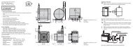
Installation and Mounting5. Installation and MountingThe sensor is an optical sensor for measurements with micrometer accuracy.iMake sure it is handled carefully when installing and operating.5.1 Sensor Mounting ILD <strong>1402</strong>-xMount the sensor via 2 screws M4.Mount the sensor in such a way thatthe laser beam is directed perpendicularlyonto the surface of the target.In case of misalignment it is possiblethat the measurement results will notalways be accurate, see Chap. 9..also.20 (.79)14 (.55)48 (1.89)12 (.47)PossibleconnectororientationMinimum bending radius PC<strong>1402</strong>-x--once: 39 mm--continuous: 78 mm--cable ø PC <strong>1402</strong>-x: 8 mmRotate the connector:Loosen the 4 screws M2 and rotatethe male connector.Fasten the male connector. Use newsealing screws M2. Connector issealed (IP 67) waiting 12 hours.Fig. 4 Dimensional drawing ILD<strong>1402</strong>-x,dimensions in mm (inches), not to scale65 (2.56)50 (1.97)40 (1.57)5(.20)2 Mounting holesø4.3/5.8Laser beam16 (.63)57 (2.24)65 (2.56)80 (3.15)4(.16)M12x1<strong>optoNCDT</strong> <strong>1402</strong>Page 20
Installation and Mounting5.2 Sensor Mounting ILD <strong>1402</strong>-xSCMount the sensor via 2 screws M4.Mount the sensor in such a way that the laser beam is directed perpendicularly onto the surface of thetarget. In case of misalignment it is possible that the measurement results will not always be accurate,see Chap. 9. also.Minimum bending radius PC<strong>1402</strong>-xSC--once: 39 mm--continuous: 78 mm57 (2 24)20 (.79)50 (1 97)40 (1.57)M12x148 (1.89)Laser beam65 (2.56)80 (3.15)16(.63)Fig. 5 Dimensions ILD<strong>1402</strong>-xSC, dimensions in mm (inches), not to scale<strong>optoNCDT</strong> <strong>1402</strong>Page 21
Installation and Mounting5.3 Pin Assignment ILD <strong>1402</strong>-xPin DescriptionColor codePC<strong>1402</strong>-x/ISpecification3 RS422 Rx+ greenSerial input4 RS422 Rx- yellowInternally terminated with 120 Ohm5 RS422 Tx+ greySerial output6 RS422 Tx- pinkTerminate externally with 120 Ohm7 +UBred 11 ... 30 VDC, typical 24 VDC / 50 mA8 Laser offblack Laser is active, if pin 8 is connected with GNDSwitch input9 Teach in violet Connected to GND for at least 30 msOpen-Collector (NPN), I = 100 mA, U = 30 VDC,max max10 Error Switch output brown short circuit proof, turn off the power supply to reset theshort circuit protection11 IOUT4 ... 20 mA whiteR = 250 W results U 1 ... 5 V with U > 11 VLoad OUT BR = 500 W results U 2 ... 10 V with U > 17 VLoad OUT B12 GND blue Supply and signal ground1/2 n.c.The shield of the cable is connected with the housing of the connector. The supplyand output cable PC<strong>1402</strong>-x/I is cable carriers suitable.One end of the cable has a molded M12 female connector, the other end has freeleads with ferrules.Fig. 6 Front view male sensor connector9 18101271165423<strong>optoNCDT</strong> <strong>1402</strong>Page 22
Installation and Mounting5.3.1 Switching off the LaserConnect pin 8 with pin 12 to switch on the laser.If you open this connection--the laser switches off,--the error output switches on,--the “State“ LED switches off.+3.3 VILD<strong>1402</strong>Laser offTeach inPin 8Pin 9Pin 12330 OhmGNDFig. 7 Circuit for laser off, analog scaling and trigger input5.3.2 Input for Analog Scaling and TriggeringIf pin 9, see Fig. 7, is selected as input to scale the analog output in the sensor configuration, see Chap.8.4.16, and if pin 9 is connected with pin 12 more than 2 sec, the scaling of the analog output starts, seeChap. 6.2. The minimum pulse duration is 30 ms, see Fig. 14.This external input can be configured as a trigger input to output the measurements also. If pin 9 is connectedwith pin 12 measurements are output at the serial or analog output. The maximum trigger frequency is500 Hz.Trigger conditions:Wiringconnect with ground, e.g. a relay or open-collector (NPN)<strong>optoNCDT</strong> <strong>1402</strong>Page 23
Installation and Mounting5.3.3 Error Output ILD<strong>1402</strong>-xThe error message is generated by:--no measuring object or measuring object beyond measuring range--poor target (reflectivity to small, transparent or mirroring object) or laser offILD<strong>1402</strong>Tmax.100 mA+24 VDC10 kOhmPin 10U = 30 VDCCE max.No error: T lockedError: T conductiveThe error output is low-active and short circuit proof.iFig. 8 External wiring for the error outputWith a user defined output scaling, see Chap. 6.2, you can use the hysteresis-free error output as aprogrammable limit switch.<strong>optoNCDT</strong> <strong>1402</strong>Page 24
Installation and Mounting5.4 Pin Assignment ILD <strong>1402</strong>-xSCPinDescriptionColor codePC<strong>1402</strong>SC-x/IPC<strong>1402</strong>SC/90-x/I1 IOUT4 ... 20 mA whiteSpecificationRLoad = 250 W results U OUT 1 ... 5 V with U B > 11 VRLoad = 500 W results U OUT 2 ... 10 V with U B > 17 V2 Error Switch output brownOpen-Collector (NPN), I = 100 mA, U = 30max maxVDC, short circuit proof, Turn off the power supply toreset the short circuit protection.3 RS422 Rx+ Serialgreen4 RS422 Rx- inputyellowInternally terminated with 120 Ohm.5 RS422 Tx+ Serialgrey6 RS422 Tx- outputpinkTerminate externally with 120 Ohm.7 GND blue Supply and signal ground8 +UBred 11 ... 30 VDC, typ. 24 VDC / 50 mA- Twisted screening black ---The laser is active in the sensor, if the power supply at the sensor is on.The shield of the cable is connected with the housing of the connector. The supply andoutput cable PC<strong>1402</strong>-xSC/I is cable carriers suitable.One end of the cable has a molded M12 8-pole female connector, the other end hasfree leads with ferrules.Fig. 9 Pin side male sensor connector76581 243<strong>optoNCDT</strong> <strong>1402</strong>Page 25
Installation and MountingError Output ILD<strong>1402</strong>-xSCThe error message is generated by:--no measuring object or measuring object beyond measuring range--poor target (reflectivity to small, transparent or mirroring object) or laser offILD<strong>1402</strong>-xSCTmax.100 mA+24 VDC10 kOhmPin 2U = 30 VDCCE max.No error: T lockedError: T conductiveThe error output is low-active and short circuit proof.iFig. 10 External wiring for the error outputWith a user defined output scaling, see Chap. 6.2, you can use the hysteresis-free error output as aprogrammable limit switch.5.5 Pin Assignment for RS422 InterfaceThe lines have to be crossed for the connection between sensor and PC.Sensor Terminal (USB converter) Colors PC<strong>1402</strong>-x/ITx+ (Pin 5) Rx+ (Pin 3) greyTx - (Pin 6) Rx - (Pin 4) pinkRx+ (Pin 3) Tx+ (Pin 2) greenRx - (Pin 4) Tx - (Pin 1) yellowGND (Pin 12, 7 1 ) GND (Pin 5)blueiDisconnect or connect the D-sub connection between RS422 and USB converter when the sensor isdisconnected from power supply only.1) For ILD<strong>1402</strong>-xSC sensors<strong>optoNCDT</strong> <strong>1402</strong>Page 26
Operation6. Operation6.1 Getting Ready for OperationInstall and assemble the <strong>optoNCDT</strong><strong>1402</strong> in accordance with the instructions set out, see Chap. 5.1 andconnect it with the indicator or monitoring unit and the power supply, having full regard to the connectioninstructions set out, see Chap. 5.3.The laser diode in the sensor ILD <strong>1402</strong>-x can only be activated if--the input “Laser on/off“ (Pin 9) or--the black wire in the PC<strong>1402</strong> sensor cableis connected to GND.The laser diode in the sensor ILD <strong>1402</strong>-XSC is activated automatically with applying the operating voltage.Once the operating voltage has been switched on the sensor runs through an initialization sequence. Thesensor ILD <strong>1402</strong>-x indicates this by the momentary activation of the “State” LED. If initialization has beenfinished, the sensor transmits the info string once in ASCII format via the serial interface independent of theselected interface. The initialization including the info string transmission takes up to 5 seconds. Within thisperiod, the sensor neither executes nor replies commands.To be able to produce reproducible measurements the sensor typically requires a start-up time of 15 minutes.Once this has elapsed the sensor will be in measurement mode and, in accordance with the factory settings,only the “State“ LED on ILD <strong>1402</strong>-x sensor is illuminated.If the “State“ LED on the sensor ILD <strong>1402</strong>-x is off, this means that--either there is no operating voltage or--the laser has been switched off.Operating Voltage--Nominal value: 24 VDC (11 ... 30 V, max. 50 mA).--Use the power supply unit for measurement instruments only, and not for drive units or similar sources ofpulse interference at the same time.Switch on the power supply unit, if wiring is done.<strong>optoNCDT</strong> <strong>1402</strong>Page 27
Operation<strong>optoNCDT</strong> <strong>1402</strong>6.2 OutputScalingThe “teaching” scalesthe analog output (4 to20 mA) for a part of themeasuring range. Thisallows you to optimizethe resolution for theanalog measurementrange. Only the currentand error output will beaffected by the 2 pointcalibration. Thereforeyou define a new startand end for the measurementrange. This“teaching” procedurecan be performed livevia the select key or viapin 9 of the connector.iWith a user definedoutput scalingyou can usethe error output,see Chap. 5.3.3,as a programmablelimit switch.iOutput scalingwith the sensorILD<strong>1402</strong>-xxxSC isonly possible viathe serial interface.20 mAAnalogoutput4 mA3 mADigital valueLED “state”Erroroutput20 mAAnalogoutput4 mA3 mADigital valueLED “state”Erroroutput16372Error16372Error0SMR161SMRDefault characteristicUser definedcharacteristicTeach 116380 3883Measuring objectMeasuring object within rangeTeach 211184Measuring objectwithin rangeEMR Measuring range16207 16368 16374ErrorEMR16382 16374ErrorPage 28
Operation20 mAAnalogoutputUser defined characteristic4 mA3 mASMRTeach 2 Teach 1Measuring objectEMRDigital value1637216380 38831118416382 16374LED “state”ErrorErrorErroroutputMeasuring objectwithin rangeFig. 11 Reverse user defined characteristicThe minimum distance of the teach values 1/2 to one other is 10 % of the measurement range.The teaching process requires a valid measuring signal. The teaching process is terminated at „no target“,„target not evaluated“, „to close to the sensor“ - beyond SMR“ or „to far from the sensor - beyond EMR“.<strong>optoNCDT</strong> <strong>1402</strong>Page 29
Operation6.2.1 Output Scaling via the “Select“ KeyKeyselectMeasuringStartteachingPosition themeasuringobject to 4 mATeach-in 1min.30 msPosition themeasuringobject to 20 mATeach-in 2 Measuringmin.30 msLEDGreen, red, yellow,depends onmeasuring positionredflashes redapprox. 2 Hzyellowflashes greenapprox. 2 Hzyellowt 0 5 min t 1 2 s t 2 30 s t 3 t 4 t 5 30 s t 6 t 7 t 8Color accordingto measuringpositionFig. 12 Timing for the output scalingThe scaling is also available via the software tool.KeyselectMeasuringHold the keyMeasuringLEDGreen, red, yellow,depends onmeasuring positionredFlashes red approx. 2 HzyellowColor accordingto measuringpositionError200 ms t 5 - t 3 = 2 st 0 5 min t 1 2 s t 2 5 st 3 t 4 t 5Fig. 13 Timing for the reset of the output scalingThe output scaling with ILD<strong>1402</strong>SC is only possible via the serial interface.<strong>optoNCDT</strong> <strong>1402</strong>Page 30
Operation6.2.2 Output Scaling via the Hardware Input, “Teach in“Pin 9MeasuringStartteachingPosition themeasuring objectto 4 mAmin.1 msTeach-in 1min.30 msPositon themeasuringobject to 20 mATeach-in 2 Measuringmin.30 msLEDGreen, red, yellow,depends onmeasuring positionredflashes redapprox. 2 Hzyellowflashes greenapprox. 2 HzyellowColor accordingto measuringpositionErrort 0 5 min t 1 2 s t 2 t 3 30 s t 4 t 5 2 s t 6 30 s t 7 t 8 2 s t 9Fig. 14 Timing for the output scalingThe scaling is also available via the software tool.Pin 9MeasuringMeasuringLEDErrorGreen, red, yellow,depends onmeasuring positionredflashes red approx. 2 Hzyellowt 0 5 min t 1 2 s t 2 5 st 3 t 4 t 5Color accordingto measuringposition200 ms t 5 - t 3 = 2 sFig. 15 Timing for the reset of the output scalingThe output scaling with ILD<strong>1402</strong>SC is only possible via the serial interface.<strong>optoNCDT</strong> <strong>1402</strong>Page 31
Operation6.3 AverageThe <strong>optoNCDT</strong><strong>1402</strong> is supplied ex factory with the default setting „moving averaging, number of averagingN = 1“ (no averaging activated).Implemented averaging methods in the sensor:--Moving average--MedianThe purpose of averaging is to:--Improve the resolution--Eliminate signal spikes--“Smooth out“ the signal.Averaging has no effect on linearity. A combination of the two averaging methods is not possible. The averagingis recommended for static measurements or slowly changing measurement values.6.3.1 Averaging Number NIn every measurement cycle (at a measurement rate of 1.5 kHz every 0.66 ms) the internal average is calculatedanew. The averaging number N indicates the number of consecutive measurement values to be averagedin the sensor.Averaging does not affect the measurement rate or data rates in digital measurement value output.6.3.2 Moving Average (Default Setting)The selected number N of successive measurement values (window width) is used to generate the movingaverage value M on the basis of the following formula:glM = glNMW (k)k=1NMW = Measuring value,N = Averaging number,k = Running indexM = Averaging value respectively output valuegl<strong>optoNCDT</strong> <strong>1402</strong>Mode:Each new measurement value is added and the first (oldest) measurement value from the averaging process(from the window) taken out again. This results in short transient recovery times for jumps in measurementvalues.Page 32
OperationExample: N = 4... 0, 1, 2, 2, 1, 3... 1, 2, 2, 1, 3, 4Measurement valuesi2, 2, 1, 34= M (n)gl2, 1, 3, 44= M (n+1)glOutputThe moving average in the <strong>optoNCDT</strong><strong>1402</strong> can only be generated for up to a maximum of 128 values.6.3.3 MedianThe median is generated from a pre-selected number of measurement values. To do so, the incoming measurementvalues (3, 5, 7 or 9 measurement values) are resorted again after every measurement. The averagevalue is then given as the median. In generating the median in the controller, 3, 5, 7 or 9 measurement valuesare taken into account, i.e. there is never a median of 1. This permits individual interference pulses to berepressed, but the measurement value curve is not smoothed to any great extent.Example: Average from five measurement values... 0 1 2 4 5 1 3 Sorted measurement values: 1 2 3 4 5 Median(n)= 3... 1 2 4 5 1 3 5Sorted measurement values: 1 3 4 5 56.4 Measurement Rate and Output RateMedian = 4(n+1)The measurement rate defines the number of measurements performed by the sensor per second. The measurementrate may be 1.5 kHz, 1.0 kHz, 750 Hz, 375 Hz or 50 Hz. Details of how to change the measurementrate, see Chap. 8.4.15.The output rate gives the actual number of measurement values at the sensor output per second. The maximumoutput rate can never exceed the measurement rate.<strong>optoNCDT</strong> <strong>1402</strong>Page 33
OperationRecommendations:--Use a high measurement rate for light colored and matt objects to be measured.--Use a low measurement rate for dark or shiny objects to be measured (e.g. surfaces covered in blacklacquer), for better measurement results.Output Maximum output rate The sensor continues to measure internally butCurrent Measurement rateholds back the output until the last measurementvalue has been issued in full. The next measurementvalue is the last valid value, with other valuesOutput rate £ Measurement rate;RS422Dependent on the transmission ratebetween being lost.(baud rate) and data format (ASCIIcode).Fig. 16 Output rates for the output typesCalculation of the output rate using the RS422 serial interface:Output rate = Measuring rate / nAbbreviations used:n = Partial factorint = Integral part of ( )b = Byte/measurement value (binary format b=2,ASCII b=6)MR = Measurement rate [Hz]n = int (b * 10 * MR / BR) + 1BR = Baud rate [Baud]Example:Measurement rate = 750 Hz, ASCII-Format (b=6), Baud rate = 115200 Baud--> n = int (0.39) + 1 = 1--> Output rate = 750 Hz / 1 = 750 Hz.<strong>optoNCDT</strong> <strong>1402</strong>Page 34
Operation6.5 TimingThe controller operates internally with real time cycles in a pipeline mode:1. Exposure: Charging the image detector in the receiver (measurement).2. Reading: Reading out of the imaging device and converting into digital data.3. Computation: Measurement computation.4. Controlling.The output through the analog and digital interface starts with the beginning of every new cycle. The analog value and digital switchoutputs are updated immediately and the digital output starts with the start bit.Each cycle takes 666 μs at a measuring rate of 1.5 kHz. The measured value N is available after each cycle with a constant lag of fourcycles in respect to the real time event. The delay between the input reaction and the signal output is therefore 2 up to 2.7 ms. Theprocessing of the cycles occurs sequentially in time and parallel in space (pipelining, see Fig. 17). This guarantees a true constant realtime data stream.Cycle 1. 2. 3. 4. 5. 6.Time max. 5 s 666 µs 1322 µs 1998 µs 2664 µs 3330 µs 3996 µsInitialisationincluding theoutput of theinfo stringExposure N Reading N Computation N Controlling N Output NExposure N+1 Reading N+1 Computation N+1 Controlling N+1 Output N+1First exposure after power up of the sensorExposure N+2 Reading N+2 Computation N+2 Controlling N+2 ...Exposure N+3 Reading N+3 Computation N+3 ...Fig. 17 Sensor timing at a measurement rate of 1.5 kHziThe sensor needs time until measuring values are available according to the set averaging number N.Exposure N+4 Reading N+4 ...... ...<strong>optoNCDT</strong> <strong>1402</strong>Page 35
Operation6.6 Triggering on ILD <strong>1402</strong>-xThe ILD<strong>1402</strong> measurement output is controllable through an external signal on the trigger input. Thereforethe external input “Teach in“ must be configured for triggering, see Chap. 8.4.16. This can be done with the“ILD<strong>1402</strong> Tool“ (“Configuration“ > “General Settings“ > “Digital Input: trigger acquisition“) also.Basics, procedure:--The sensor measures and calculates also, if no trigger pulses are pending.--The data output starts with a falling edge of the trigger signal.--Sensor outputs the measurement value with a delay T Tof 1.4 up to 2 ms.--A new trigger pulse can be sent.+5 VTrigger signalPin 9Output+2 V+0.8 V0 VHighLowt > 5 µsNtI > T TValue 1 Value 2TimetNtITTNon-pulse periodPulse intervalDelay timeT = 1.4 … 2 msTtrue for a measurementrate of 1.5 kHzand a baud rate of115.200 BaudT = 1.4 ... 2 ms T T= 1.4 ... 2 msTMaximum trigger rate:appr. 500 HzFig. 18 TimingYou get a digital measurement value on the output for each trigger signal, see Chap. 8.4.10, see Chap. 8.4.11(data output). The analog output is actualized with any trigger signal, if you use the analog output.iAn averaging of the measuring values has no effect on the delay time T T. Consider certainly, that thecontroller needs time for the averaging, until measuring values are available according to the set averagingnumber N.<strong>optoNCDT</strong> <strong>1402</strong>Page 36
Measurement Value Output7. Measurement Value OutputThe <strong>optoNCDT</strong><strong>1402</strong> can issue the measurement values either via the analog output or the RS422 serial interface.The two different types of output cannot be used concurrently. When using the cable PC<strong>1402</strong>-x / U, thevoltage output is 1 ... 5 V, see Chap. 5.3.7.1 Current OutputMax. range4 mA ... 20 mAOutput amplification I 16 mA = 100 % Measuring rangeOUTError value:3.75 mA (±10 µA)20 mAAnalogoutput4 mA3 mADigital value 163720SMR161Default characteristicMeasuring objectEMRMeasuring ange16207 16368 16374Proceed as followsto set the sensor intooperation after a shortcircuiton the analogoutput:Switch off thesensor’s powersupply.Wait appr. 3 s.Switch on thesensor’s powersupply.Fig. 19 Current signal outputCalculation of measurement value x in mm from analog currentReference value SMRReference value MMR:MR [mm]MR [mm]x [mm] = (I OUT - 4 mA)* x [mm] = (I OUT - 4 mA)*- MR/216 [mA]16 [mA]Example: Measuring range = 10 mm, I = 12 mA; Result: x = 5 mm or x = 0 mmOUT<strong>optoNCDT</strong> <strong>1402</strong>Page 37
Measurement Value Output7.2 Digital Value Output7.2.1 Data Protocol ILD1401The digital measurement values are issued as unsigned digital values (raw values).Digital value Used for0 ... 39 SMR back-up40 ... 4055 Measurement range4056 ... 4095 EMR back-upCalculation of a measurement value in mm from digital output:Reference value Start of Measuring Range:Reference value Midrangex [mm] = (digital OUT *1.024096- 0.01) * MR [mm]x [mm] = (digital OUT *1.024096- 0.51) * MR [mm]Example: MR =10 mm, digital value = 2048, measurement value = 5 mm or 0 mmNote: A digital value can be calculated from a measurement value (millimeter) as follows:x [mm]digitalOUT= + 0.01 *MR [mm]40961.02<strong>optoNCDT</strong> <strong>1402</strong>Page 38
Measurement Value Output7.2.2 Data Protocol ILD<strong>1402</strong>The digital measurement values are issued as unsigned digital values (raw values).Digital value Used for Digital value Used for0 ... 16367 Value range 16208 ... 16367 EMR back-up (1 %)0 ... 160 SMR back-up (1 %) 16370 ... 16383 Error codes161 ... 16207 Measurement rangeCalculation of a measurement value in mm from digital output:Reference value Start of Measuring Range:Reference value Midrange1.02x [mm] = (digital OUT *16368- 0.01) * MR [mm]x [mm] = (digital OUT *1.02- 0.51) * MR [mm]16368Example: MR =10 mm, digital value = 8184, measurement value = 5 mm or 0 mmNote: A digital value can be calculated from a measurement value (millimeter) as follows:x [mm]digitalOUT= + 0.01 *MR [mm]163681.02<strong>optoNCDT</strong> <strong>1402</strong>7.3 Digital Error CodesDigital error codes are issued in the same way as measurement values.Value range for error codes: 16370 ... 16384 (digital ) OUT--16370 no object detected--16372 too close to the sensor--16374 too far from the sensor--16376 target can not be evaluated--16378 external laser off--16380 target moves towards the sensor--16382 target moves away from sensor--16383 internal errorPage 39
Serial Interface RS4228. Serial Interface RS422PC<strong>1402</strong>-x/IF2008ILD<strong>1402</strong> IF2008 PCFig. 20 System structure to operate the interface card IF2008Pin Signal Signal PinSensor 1,Sensor 312-pol.connectorSensor 2,Sensor 412-pol.connector7 (8 1 ) 24 V +24 V supply3 Rx + (Input) Sensor 1/3 TxD+ 24 Rx - (Input) Sensor 1/3 TxD - 15 Tx + (Output) Sensor 1/3 RxD+ 46 Tx - (Output) Sensor 1/3 RxD - 312 (7 1 ) GND 0 V supply 5Sensor 1/3 TRG+ 6Sensor 1/3 TRG - 7Sensor 2/4 TRG+ 8Sensor 2/4 TRG - 97 (8 1 ) 24 V +24 V supply 103 Rx + Sensor 2/4 TxD+ 124 Rx - Sensor 2/4 TxD - 115 Tx + Sensor 2/4 RxD+ 146 Tx - Sensor 2/4 RxD - 1312 (7 1 ) GND 0 V supply 5Fig. 21 Pin assignment PC<strong>1402</strong>-x/IF2008Pin assignment IF2008IF2008,X1 und X2,15-pol.Sub-DRequired cables and programroutines--IF2008RS422 interface card, for1 to 4 laser-optic sensorsfrom the ILD<strong>1402</strong> seriesand 2 encoders, includingMEDAQlib programminginterface.--PC<strong>1402</strong>-x/IF2008Power supply and outputcable,x = length with 3, 6 or 8 m.Alternatively, data can betransferred with the demosoftware (ILD<strong>1402</strong> Tool) and aRS422 converter to USB, seeChap. 11..1) For the ILD<strong>1402</strong>-xSC sensorsresp. the PC<strong>1402</strong>SC-x/IF2008 cables.<strong>optoNCDT</strong> <strong>1402</strong>Page 40
Serial Interface RS4228.1 Interface ParameterThe <strong>optoNCDT</strong><strong>1402</strong> comes with a RS422 serial interface to enable the sensor to be operated from a standardcomputer and measurement values and error codes to be transferred.The sensor can operate with two different data protocols:--Data protocol ILD1401--Data protocol ILD<strong>1402</strong>Default settings Data protocol ILD1401 Data protocol ILD<strong>1402</strong>Baud rate 38400 115200ParitynoneData bits 8Start/stop bit 18.2 Data Format for Measurement Values and Error Codes8.2.1 Binary FormatThe data word is comprised of two consecutive bytes (H-byte/L-byte). One flag bit in each byte differentiatesa high from a low byte.Start 1 7 Bit MSB Stop Start 0 7 Bit LSB StopConversion of the binary data format:For conversion purposes the high and low bytes must be identified on the basis of the first bit (flag bit), theflag bits deleted and the remaining 2 x 7 bits compiled into 14 bit data word.Reception:H-Byte 1 D13 D12 D11 D10 D9 D8 D7L-Byte 0 D6 D5 D4 D3 D2 D1 D0Result of conversion0 0 D13 D12 D11 D10 D9 D8 D7 D6 D5 D4 D3 D2 D1 D0<strong>optoNCDT</strong> <strong>1402</strong>Page 41
Serial Interface RS422iIf the sensor operates with the ILD1401 data protocol, the measurement value is a 12 bit word, e.g. thebits D12 and D13 are 0.Replies with a length of 4 Bytes must be swapped according to the following rule:Reception: 0 1 2 3 4 5 6 7Conversion: 3 2 1 0 7 6 5 4This rule does not apply to values.8.2.2 ASCII FormatOutput of 5 characters (digits) in ASCII code for the digital value + 1 tag „CR“ (= 0x0D), i.e. a total of 6 characters.Digital values with just 3 or 4 digits are preceded by blank characters.Example: Digital value 2099Transfer: “_2099“ (preceded by 1 blank character) „CR“ASCII code (Hex.) 0x20 0x32 0x30 0x39 0x39 0x0DCharacters SP 2 0 9 9 CRiASCII characters can be easily shown using a terminal program.8.2.3 Request the Data ProtocolPC transmits “---R”.Sensor replies“---14CI1“ Sensor operates with the ILD1401 data protocol or“---14CI2“ Sensor operates with the ILD<strong>1402</strong> data protocol.<strong>optoNCDT</strong> <strong>1402</strong>Page 42
Serial Interface RS4228.3 Data Protocol ILD14018.3.1 Setup of the CommandsThe commands for the sensor are transmitted in full duplex mode. Each instruction has a head, the ID, thecommand, the quantity and data if required (parameter, if quantity > 0).The head contains 4 bytes to identify a connection towards the sensor. The ID consists of 2 bytes, the commandand quantity) consists of 1 byte. The complete string (without parameter) has a length of 8 bytes. Thequantity is a equivalent of the subsequent bytes.Each complete command is returned by the sensor. The answer contains the 2 ID bytes (equivalent to thetransmitted ID), the modified command byte, the quantity and response informations. The modified commandbyte = command OR masked with 0x80 if the command was transmitted successful. If an error happensthe modified command byte = command OR masked with 0xC0 . In the case of an error the quantityhexhexis 1 and contains the error code.Byte 1 Byte 2 Byte 3 Byte 4 Byte 5 Byte 6 Byte 7 Byte 8 Byte 9Head ID Command Quantity ParameterFig. 22 Set-up of a command in the transmitterByte 1 Byte 2 Byte 3 Byte 4 Byte 5ID Command OR masked with 0x80 hex Quantity ParameterFig. 23 Set-up of a command in the receiver, error-free transmittedByte 1 Byte 2 Byte 3 Byte 4 Byte 5ID Command OR masked with 0xC0 hex Quantity = 1 Error codeFig. 24 Set-up of a command in the receiver, faulty transmissionError codeDescription Bytes ValueCommand error 1 2Faulty number of parameters 1 3Time out 1 4<strong>optoNCDT</strong> <strong>1402</strong>Page 43
Serial Interface RS4228.3.2 Overview of CommandsInformation commands0x0900 Chap. 8.3.4 VERSION Shows the software version0x0C00 Chap. 8.3.3 INFO Shows the sensor dataFilter0x1001 Chap. 8.3.5 MEDIAN Median filter over 3 values, on/offMeasurement value output0x0E01 Chap. 8.3.6 OUTPUTCHANNEL Output analog / digitalError output (analog output)0x0F01 Chap. 8.3.7 SAVELASTMV Behavior of the analog output in case of errorsReset0x0100 Chap. 8.3.8 BOOT Reboots the sensorSwitch data protocol ILD1401 / ILD<strong>1402</strong>0x1100 Chap. 8.3.9 SET_CIMODE_<strong>1402</strong> Sensor operates with data protocol ILD<strong>1402</strong>0x2D2D2D52hChap. 8.3.10 GET_CI_MODERequests the command interpreter state ofthe sensor<strong>optoNCDT</strong> <strong>1402</strong>Page 44
Serial Interface RS4228.3.3 Reading the Sensor Parameters, INFOName:Description:INFOSupplies the info string.Format Byte 1 Byte 2 Byte 3 Byte 4 Byte 5 Byte 6 Byte 7 Byte 8 Byte 9“+” “+” “+” 0x0D „I“ „L“ 0x0C 0x00 noneReply Byte 1 Byte 2 Byte 3 Byte 4 Byte 5„I“ „L“ 0x8C Quantity 1 Info stringByte 1 Byte 2 Byte 3 Byte 4“I“ “L“ 0x8C 0x89Info is a readable ASCII stringArticle 4120154Option 000Series 1234570MR 50SoftVer 1.001Date 09/01/23Out Channel analogAnlog Error error valueFilter offCommand error-freeByte 1 Byte 2 Byte 3 Byte 4 Byte 5“I“ “L“ 0xCC 0x01 Error codeFaulty command1) Number of bytes depends on the content of the response.<strong>optoNCDT</strong> <strong>1402</strong>Page 45
Serial Interface RS4228.3.4 Reading the Software Version, VERSIONName:Description:VERSIONThe sensor transmitts the software version.Format Byte 1 Byte 2 Byte 3 Byte 4 Byte 5 Byte 6 Byte 7 Byte 8 Byte 9“+” “+” “+” 0x0D „I“ „L“ 0x09 0x00 noneReply Byte 1 Byte 2 Byte 3 Byte 4 Byte 5„I“ „L“ 0x89 Quantity Info stringCommand error-freeByte 1 Byte 2 Byte 3 Byte 4“I“ “L“ 0x89 0x07Version is a readable ASCII string: 1.001Default setting:Median offFaulty command Byte 1 Byte 2 Byte 3 Byte 4 Byte 5“I“ “L“ 0xC9 0x01 Error code8.3.5 Average On/Off, MEDIANName:MEDIANDescription: Switches between „Averaging on“ and „Averaging off“. The median is generated from a presetnumber of measurement values. Here the inputted measurement values (3 measurement values) are resortedafter each measurement. The average value is then outputted as the median. When the median is generatedin the controller only 3 measurement values are taken into account, i.e. a 0 median is not possible. Thismeans that individual interference pulses can be suppressed. The measurement value curve is not smoothedto a great extent.Byte 9 = 0; Median offByte 9 = 1; Median on<strong>optoNCDT</strong> <strong>1402</strong>Page 46
Serial Interface RS422Format Byte 1 Byte 2 Byte 3 Byte 4 Byte 5 Byte 6 Byte 7 Byte 8 Byte 9“+” “+” “+” 0x0D „I“ „L“ 0x10 0x01 Median ON/OFFDefault setting:analog outputReply Byte 1 Byte 2 Byte 3 Byte 4 Byte 5„I“ „L“ 0x90 0x00 noneCommand error-freeByte 1 Byte 2 Byte 3 Byte 4 Byte 5“I“ “L“ 0xD0 0x01 Error codeFaulty command8.3.6 Digital or Analog Data Output, OUTPUTCHANNELName:OUTPUTCHANNELDescription: Selects the output channel (analog / digital) for the sensor. If the digital output is selected theserial interface transmits measured values with a data rate of 1.5 kHz. If the analog output is selected the serialinterface transmits the commands and the responses only.Byte 9 = 0; analogByte 9 = 1; digitalFormat Byte 1 Byte 2 Byte 3 Byte 4 Byte 5 Byte 6 Byte 7 Byte 8 Byte 9“+” “+” “+” 0x0D „I“ „L“ 0x0E 0x01 ChannelReply Byte 1 Byte 2 Byte 3 Byte 4 Byte 5„I“ „L“ 0x8E 0x00 noneCommand error-freeByte 1 Byte 2 Byte 3 Byte 4 Byte 5“I“ “L“ 0xCE 0x01 Error codeFaulty command<strong>optoNCDT</strong> <strong>1402</strong>Page 47
Serial Interface RS422Default setting:„Error code“, also3.75 mA on the analogoutput8.3.7 Sensor Behavior in Error Case, SAVELASTMVName:Description:SAVELASTMVSwitches between „Hold last value“ and „Error code“ of the analog output.Format Byte 1 Byte 2 Byte 3 Byte 4 Byte 5 Byte 6 Byte 7 Byte 8 Byte 9“+” “+” “+” 0x0D „I“ „L“ 0x0F 0x01 Output typeReply Byte 1 Byte 2 Byte 3 Byte 4 Byte 5„I“ „L“ 0x8F 0x00 noneCommand error-freeByte 1 Byte 2 Byte 3 Byte 4 Byte 5“I“ “L“ 0xCF 0x01 Error codeFaulty commandOutput typeDescription Bytes ValueOutput type = „Hold last value“ (in the case of an error the last valid measured value isshown on the analog output)1 0Output type = „Error code“ (in the case of an error a value < 4 mA is output) 1 1<strong>optoNCDT</strong> <strong>1402</strong>Page 48
Serial Interface RS4228.3.8 Reset Sensor, BOOTName:BOOTDescription: The sensor makes a software reset. The default settings for output and filter are used.--Current output: error code--Median offThe response is sent before the reset is done.Format Byte 1 Byte 2 Byte 3 Byte 4 Byte 5 Byte 6 Byte 7 Byte 8 Byte 9“+” “+” “+” 0x0D „I“ „L“ 0x01 0x00 noneReply Byte 1 Byte 2 Byte 3 Byte 4 Byte 5„I“ „L“ 0x81 0x00 noneCommand error-freeByte 1 Byte 2 Byte 3 Byte 4 Byte 5“I“ “L“ 0xC1 0x01 Error codeFaulty command8.3.9 Changing Data Protocol, SET_CIMODE_<strong>1402</strong>Name:SET_CIMODE_<strong>1402</strong>Description: Switches the sensor into the ILD<strong>1402</strong> data protocol. The sensor replies with the ILD1401 dataprotocol, after sending the reply the sensor switches to the mode and maintains a reset.Format Byte 1 Byte 2 Byte 3 Byte 4 Byte 5 Byte 6 Byte 7 Byte 8 Byte 9“+” “+” “+” 0x0D „I“ „L“ 0x11 0x00 noneReply Byte 1 Byte 2 Byte 3 Byte 4 Byte 5„I“ „L“ 0x91 0x00 noneCommand error-freeByte 1 Byte 2 Byte 3 Byte 4 Byte 5“I“ “L“ 0xD1 0x01 FehlercodeFaulty command<strong>optoNCDT</strong> <strong>1402</strong>Page 49
Serial Interface RS4228.3.10 Request Data Protocol, GET_CI_MODEName:Description:GET_CI_MODERequests the state of the sensors command interpreter.Format: 31 24 23 16 15 8 7 0 hex„-“ „-“ „-“ „R“ 0x2D2D2D52Reply: 31 24 23 16 15 8 7 0 hex„-“ „-“ „-“ „1“ 0x2D2D2D31„4“ „C“ „I“ 0x3X 0x3443493XOptions for X:X = 1, the command interpreter of the sensor operates with the ILD1401 data protocol.X = 2, the command interpreter of the sensor operates with the ILD<strong>1402</strong> data protocol. Note: The sensoruses a different protocol!8.4 Data Protocol ILD<strong>1402</strong>8.4.1 Setup of the CommandsThe commands for the sensors are comprised of command data which are transmitted in full duplex mode.Each command packet is comprised of a whole number multiple of 32 bit words, see Fig. 25.<strong>optoNCDT</strong> <strong>1402</strong>31 24 23 16 15 8 7 0 Contents1 Header Start word2 IDSensor identifier, Command header (2 words)e.g. “ILD1“3 Command (16 Bit) Package length (16 Bit) Command code Data word quantity n+24 Data 1 1 st Data word (4 Bytes)5 ... ...6 Data (n) n th Data word (4 Bytes)Fig. 25 Structure of a command packetPage 50
Serial Interface RS422Since most serial interfaces use an 8 bit data format, 4 consecutive bytes are combined into a 32 bit word.Each command packet has a header consisting of two 32 bit words followed by the command and, if required,other data as well. The top two bits (No. 31 and 30) are always “0“ in the transmitted command.8.4.2 Communication without ErrorNo start word is transmitted if the sensor replies to a command. The 1st word is then the sensor identifier. Thesecond word is the command with set MSB (Bit 31 = 1, corresponding an OR operation of the command with0x8000) and the new package length if there was no error during communication. With longer answers (e.g.GET_INFO) the package length is larger according to the quantity of data words to be transmitted. A firm32 bit word 0x20200D0A forms the conclusion of the answer. The conclusion word is not a data word.8.4.3 Communication with ErrorIf the sensor detects an error during the execution of a command, the second highest bit (bit 30) of the commandis also set (the command is OR operated with 0xC000). Additionally a command error code is transferredas data word, see Fig. 26. The resulting package length now amounts to 3 data words. The reply isfinished with a 32 bit word 0x20200D0A (2 blank charecters + CR + LF).Error Code X Description1 Command unknown2 Incorrect parameter value3 Invalid parameter4 Time out5 Command failed6 Warning for averaging type and averaging number 1Fig. 26 Command error codes1), see Chap. 8.4.7<strong>optoNCDT</strong> <strong>1402</strong>Page 51
Serial Interface RS4228.4.4 OverviewInformation command0x20490002 Chap. 8.4.5 GET_INFO Shows sensor data0x204A0002 Chap. 8.4.6 GET_SETTINGS Shows sensor settingsAverage0x207F0004 Chap. 8.4.7 SET_AV Sets average type and valueMeasurement value output0x20760002 Chap. 8.4.8 DAT_OUT_OFF Stops measurement value output0x20770002 Chap. 8.4.9 DAT_OUT_ON Permanent measurement value output0x20F40003 Chap. 8.4.11 SET_OUTPUTMODE Output mode0x20F50003 Chap. 8.4.12 SET_OUTPUTTIME_MS Output time in msSwitch output settings0x20900003 Chap. 8.4.10 SET_OUTPUT_CHANNEL Output: current or RS422Speed0x20800003 Chap. 8.4.14 SET_BAUDRATE 115.2 / 57.6 / 38.4 / 19.2 / 9.6 kBaud0x20850003 Chap. 8.4.15 SET_SCANRATE Measurement rate: 1.5 kHz; 1.0 kHz; 750 Hz; 375 HzError output (analog output)0x20810003 Chap. 8.4.13 SET_ANALOG_ERROR_HANDLER Behavior of the analog output in the case of an errorExternal input0x20F80003 Chap. 8.4.16 SET_EXT_INPUT_MODE Scaling, triggeringSwitching off the laser (external)0x20870002 Chap. 8.4.19 LASER_ON Switches the laser on0x20860002 Chap. 8.4.19 LASER_OFF Switches the laser offMeasurement value data format0x20880003 Chap. 8.4.20 ASCII_OUTPUT Options: ASCII / BinaryKey lock0x20600003 Chap. 8.4.21 SET_KEYLOCK Key enabled / locked / auto lockReset0x20F10002 Chap. 8.4.23 SET_DEFAULT Reset to default factory settings0x20F00002 Chap. 8.4.22 RESET_BOOT Reboot the sensor<strong>optoNCDT</strong> <strong>1402</strong>Page 52
Serial Interface RS422Memory mode0x20F70003 Chap. 8.4.24 SET_SAVE_SETTINGS_MODE Volatile / nonvolatileScaling values0x20F90004 Chap. 8.4.25 SET_TEACH_VALUE Sets T1 + T2 0 ... 163680x20FA0002 Chap. 8.4.26 RESET_TEACH_VALUE Sets T1 = 0 / T2 = 16368Search algorithm0x20FB0003 Chap. 8.4.17 SET_PEAKSEARCHING First peak, last peak, global maximumThreshold0x20FC0003 Chap. 8.4.18 SET_THRESHOLDLower than standard, standard, higher than standard,highestSwitch data protocol0x20F20002 Chap. 8.4.27 SET_CIMODE_1401 Sensor operates with ILD1401 data protocol0x2D2D2D52 Chap. 8.4.28 GET_CI_MODE Requests the command interpreter state of the sensor8.4.5 Reading the Sensor Parameters, GET_INFOName: GET_INFODescription: Supplies the info string. This shows all parameters currently stored in the sensor.Format: 31 24 23 16 15 8 7 0 hex„+“ „+“ „+“ 0x0d („CR“) 0x2B2B2B0D„l“ „L“ „D“ „1“ 0x494C44310x20 0x49 0x00 0x02 0x20490002<strong>optoNCDT</strong> <strong>1402</strong>Page 53
Serial Interface RS422Reply: 31 24 23 16 15 8 7 0 hex„l“ „L“ „D“ „1“ 0x494C44310xA0 0x49 0x00 0xxx 0xA04900xxInfo string is a readable ASCII character string:ILD <strong>1402</strong>: StandardA/N: 4120154O/N: 000S/N: 1234570MR: 50SoftVer: 1.001.796BootVer: 1.001.16Date: 09/01/23Out Channel: analog | digitalAnalog Error: last value | error value | error value after cycles xx //xx is 2 up to 99Filter Type: moving average | medianFilter Number: xx //with moving average xx is 1 up to 128, with median xx is 7, 5, 7 or 9Scanrate: xxHz //xx is 1500 Hz, 1000 Hz, 750 Hz, 375 Hztype of digital output: binary | asciimode of analog/digital output: continuous | time | triggeroutput time: xx //xx is time in ms 1key status: unlock | lock | auto lockmode of save setting: no save | save at each timemode of extern input: as teach in | as output triggerpeak searching: global maximum | first peak | last peakTeach value 1: xx //(xx is 1.0 up to 16368.0Teach value 2: xx //xx is 1.0 up to 16368.00x20 0x20 0x0D 0x0A 0x20200D0A| = separates variants from each other// = beginning of a comment1) Output time is available only, if ”mode of analog/digital output“ is set to ”time”<strong>optoNCDT</strong> <strong>1402</strong>Page 54
Serial Interface RS4228.4.6 Reading the Sensor Settings, GET_SETTINGSName: GET_SETTINGSDescription: Supplies the current sensor settings.Swap the received bytes according, see Chap. 8.2.1.These are as follows:Output channel--0 = Current--1 = DigitalTeach value 10.0 … 16368.0e. g. float: 3027.426 = hexadecimal: 0x453d36d1Teach value 20.0 … 16368.0e. g. float: 11068.851 = hexadecimal: 0x462cf367Analog error handler--0 = hold last value--1 = error output--2…99 hold last value for 2…99 images respectively cyclesAverage type--0 = moving average--1 = MedianAverage value--1…128 moving average, if average type = 0--3, 5, 7, 9 Median, if average type = 1Measurement rate--0 = 1500 Hz--1 = 1000 Hz--2 = 750 Hz--3 = 375 Hz--4 = 50 HzBaud rate--0 = 115200 Baud--1 = 57600 Baud--2 = 38400 Baud--3 = 19200 Baud--4 = 9600 BaudDigital output type--0 = Binary--1 = ASCIIAnalog, digital output mode--0 = continuously each measurement, depending on baud rateand the measuring frequency;delay = (Bit quantity / Baud rate) * measuring frequency [Hz](if delay < 0, delay = delay +1)delay = number of cycles with no serial output--1 = time-based, see output time [ms]--2 = trigger controlled, see external input modeOutput time [ms]1…65535Key lock--0 = key enabled--1 = key locked--2 = automatic key lock after 5 min power is on<strong>optoNCDT</strong> <strong>1402</strong>Page 55
Serial Interface RS422Save settings mode--0 = transmitted settings are stored in the RAM and are valid until power off--1 = transmitted settings are stored in the FLASH and are valid, even after power off/onExternal input type--0 = external input is used for scaling--1 = external input is used as trigger input (trigger controlled output)Peak searching--0 = peak with global maximum--1 = first peak, direction pixel 0 up to pixel 127, left to right--2 = last peak, direction pixel 0 up to pixel 127, left to rightThreshold--0 = lower than standard--1 = standard--2 = higher than standard--3 = highestMeasuring range [mm]--XXX X = 1 ...65535Reserved 1Reserved 2Reserved 3Reserved 4<strong>optoNCDT</strong> <strong>1402</strong>Page 56
Serial Interface RS422Format: 31 24 23 16 15 8 7 0 hex„+“ „+“ „+“ 0x0d („CR“) 0x2B2B2B0D„l“ „L“ „D“ „1“ 0x494C44310x20 0x4A 0x00 0x02 0x204A0002Reply: 31 24 23 16 15 8 7 0 hex„l“ „L“ „D“ „1“ 0x494C44310xA0 0x4A 0x00 0x17 0xA04A0017Output channel0x00 0x00 0x00 0x0X 0x0000000XTeach value 10xXX 0xXX 0xXX 0xXX 0xXXXXXXXXTeach value 20xXX 0xXX 0xXX 0xXX 0xXXXXXXXXAnalog error handler0x00 0x00 0x00 0xXX 0x000000XXAverage type0x00 0x00 0x00 0x0X 0x0000000XAverage value0x00 0x00 0x00 0xXX 0x000000XXMeasurement rate0x00 0x00 0x00 0x0X 0x0000000XBaud rate0x00 0x00 0x00 0x0X 0x0000000XDigital output type0x00 0x00 0x00 0x0X 0x0000000XAnalog digital output mode0x00 0x00 0x00 0x0X 0x0000000XOutput time0x00 0x00 0xXX 0xXX 0x0000XXXX<strong>optoNCDT</strong> <strong>1402</strong>Page 57
Serial Interface RS422Key lock0x00 0x00 0x00 0x0X 0x0000000XSave settings mode0x00 0x00 0x00 0x0X 0x0000000XExternal input type0x00 0x00 0xXX 0xXX 0x0000XXXXPeak searching0x00 0x00 0x00 0x0X 0x0000000XThreshold0x00 0x00 0x00 0x0X 0x0000000XMeasuring range0x00 0x00 0xXX 0xXX 0x0000XXXXReserved 10x00 0x00 0x00 0x0X 0x00000000Reserved 20x00 0x00 0xXX 0xXX 0x00000000Reserved 30x00 0x00 0x00 0x0X 0x00000000Reserved 40x00 0x00 0x00 0x0X 0x00000000Last data word0x20 0x20 0x0D 0x0A 0x20200D0A<strong>optoNCDT</strong> <strong>1402</strong>Page 58
Serial Interface RS422Default setting:moving average 1, thusno averaging8.4.7 Average Type and Average Number, SET_AVName:SET_AVDescription: Sets the average type and the average number N.Parameter:--Average type• X = 0 --> Moving average• X = 1 --> Median--Average number• XX = 1 ... 128 --> Moving average, if average type = moving average• XX = 3, 5, 7, 9 --> Median, if average type = MedianFormat: 31 24 23 16 15 8 7 0 hex„+“ „+“ „+“ 0x0d („CR“) 0x2B2B2B0D„l“ „L“ „D“ „1“ 0x494C44310x20 0x7F 0x00 0x04 0x207F00040x00 0x00 0x00 0x0X 0x0000000X0x00 0x00 0x00 0xXX 0x000000XXReply: 31 24 23 16 15 8 7 0 hex„l“ „L“ „D“ „1“ 0x494C44310xA0 0x7F 0x00 0x02 0xA07F00020x20 0x20 0x0D 0x0A 0x20200D0A<strong>optoNCDT</strong> <strong>1402</strong>Page 59
Serial Interface RS4228.4.8 Stopping the Measurement Value Output, DAT_OUT_OFFName:DAT_OUT_OFFDescription: Switches off the digital output for the measurement values. This has no effect on communicationwith the sensor via the digital interface. This command has a higher priority in trigger mode. The commandis volatile. Therefore data out is on after power on.Format: 31 24 23 16 15 8 7 0 hex„+“ „+“ „+“ 0x0d („CR“) 0x2B2B2B0D„l“ „L“ „D“ „1“ 0x494C44310x20 0x76 0x00 0x02 0x20760002Reply: 31 24 23 16 15 8 7 0 hex„l“ „L“ „D“ „1“ 0x494C44310xA0 0x76 0x00 0x02 0xA07600020x20 0x20 0x0D 0x0A 0x20200D0A8.4.9 Starting the Measurement Value Output, DAT_OUT_ONName:DAT_OUT_ONDescription: Switches on the digital data output for the measurement values. The output channel (outputtype) must also be set to the digital output, otherwise the measurement data cannot be received from thesensor.Format: 31 24 23 16 15 8 7 0 hex„+“ „+“ „+“ 0x0d („CR“) 0x2B2B2B0D„l“ „L“ „D“ „1“ 0x494C44310x20 0x77 0x00 0x02 0x20770002Reply: 31 24 23 16 15 8 7 0 hex„l“ „L“ „D“ „1“ 0x494C44310xA0 0x77 0x00 0x02 0xA07700020x20 0x20 0x0D 0x0A 0x20200D0A<strong>optoNCDT</strong> <strong>1402</strong>Page 60
Serial Interface RS422Default setting:analog output8.4.10 Digital or Analog Data Output, SET_OUTPUT_CHANNELName:Description:SET_OUTPUT_CHANNELSets the output type for the measurement values.Parameter:--X = 0 --> Analog output (4 ... 20 mA)--X = 1 --> Digital output (RS422)Format: 31 24 23 16 15 8 7 0 hex„+“ „+“ „+“ 0x0d („CR“) 0x2B2B2B0D„l“ „L“ „D“ „1“ 0x494C44310x20 0x90 0x00 0x03 0x209000030x00 0x00 0x00 0x0X 0x0000000XReply: 31 24 23 16 15 8 7 0 hex„l“ „L“ „D“ „1“ 0x494C44310xA0 0x90 0x00 0x02 0xA09000020x20 0x20 0x0D 0x0A 0x20200D0A<strong>optoNCDT</strong> <strong>1402</strong>Page 61
Serial Interface RS422Default setting:continuously8.4.11 Characteristics for Digital or Analog Data Output, SET_OUTPUTMODEName:SET_OUTPUTMODEDescription: Sets the output characteristics.--X = 0 --> continuously each measurement, depending on baud rate and the measuring frequency;delay = (Bit quantity / Baud rate) * measuring frequency [Hz], if delay < 0, delay = delay +1)delay = number of cycles with no serial output--X = 1 --> time-based, see Chap. 8.4.12.--X = 2 --> trigger controlled, see Chap. 8.4.16.Format: 31 24 23 16 15 8 7 0 hex„+“ „+“ „+“ 0x0d („CR“) 0x2B2B2B0D„l“ „L“ „D“ „1“ 0x494C44310x20 0xF4 0x00 0x03 0x20F400030x00 0x00 0x00 0x0X 0x0000000XReply: 31 24 23 16 15 8 7 0 hex„l“ „L“ „D“ „1“ 0x494C44310xA0 0xF4 0x00 0x02 0xA0F400020x20 0x20 0x0D 0x0A 0x20200D0A<strong>optoNCDT</strong> <strong>1402</strong>Page 62
Serial Interface RS422Default setting:500 ms8.4.12 Set Output Time, SET_OUTPUTTIME_MSName:Description:SET_OUTPUTTIME_MSSets the output time for the analog or digital output value to be updated.Will be applicable at time-based measurement value output, see Chap. 8.4.11.Parameter:--XXXX = 1 … 65535 [ms].Format: 31 24 23 16 15 8 7 0 hex„+“ „+“ „+“ 0x0d („CR“) 0x2B2B2B0D„l“ „L“ „D“ „1“ 0x494C44310x20 0xF5 0x00 0x03 0x20F500030x00 0x00 0x00 0x0X 0x0000000XReply: 31 24 23 16 15 8 7 0 hex„l“ „L“ „D“ „1“ 0x494C44310xA0 0xF5 0x00 0x02 0xA0F500020x20 0x20 0x0D 0x0A 0x20200D0A<strong>optoNCDT</strong> <strong>1402</strong>Page 63
Serial Interface RS422Default setting:error value8.4.13 Error Output (Analog output), SET_ANALOG_ERROR_HANDLERName:Description:SET_ANALOG_ERROR_HANDLERHold or not hold last measurement value.Parameter:--X = 0 --> hold last measurement value--X = 1 --> error value (3.75 mA)--X = 2 … 99 --> hold last measurement value for 2 … 99 images respectively cyclesThis command only affects the analog output. If set to X = 0, the last valid measurement value will continueto be issued if an error occurs (no object, invalid object, object outside the measurement range or laserturned off). If set to X = 1, an error signal will be generated for the current output that has an error value of3.75 mA. If set to X = 2 ... 99, the last valid measurement value will continue to be issued for X measuringcycles before an error signal is generated on the analog output.Format: 31 24 23 16 15 8 7 0 hex„+“ „+“ „+“ 0x0d („CR“) 0x2B2B2B0D„l“ „L“ „D“ „1“ 0x494C44310x20 0x81 0x00 0x03 0x208100030x00 0x00 0x00 0x0X 0x0000000XReply: 31 24 23 16 15 8 7 0 hex„l“ „L“ „D“ „1“ 0x494C44310xA0 0x81 0x00 0x02 0xA08100020x20 0x20 0x0D 0x0A 0x20200D0A<strong>optoNCDT</strong> <strong>1402</strong>Page 64
Serial Interface RS422Default setting:115200 Baud8.4.14 Set Baud Rate, SET_BAUDRATEName:Description:Parameter:--X = 0 --> 115200--X = 1 --> 57600--X = 2 --> 38400--X = 3 --> 19200--X = 4 --> 9600SET_BAUDRATESets the transmission rate.The sensor still sends the reply with the old baud rate and only switches to the new baud rate once the replyhas been sent. The output rate reduces automatically when the baud rate is changed because individualmeasurement values are skipped.Do not forget to change your programs baud rate.iFormat: 31 24 23 16 15 8 7 0 hex„+“ „+“ „+“ 0x0d („CR“) 0x2B2B2B0D„l“ „L“ „D“ „1“ 0x494C44310x20 0x80 0x00 0x03 0x208000030x00 0x00 0x00 0x0X 0x0000000XReply: 31 24 23 16 15 8 7 0 hex„l“ „L“ „D“ „1“ 0x494C44310xA0 0x80 0x00 0x02 0xA08000020x20 0x20 0x0D 0x0A 0x20200D0A<strong>optoNCDT</strong> <strong>1402</strong>Page 65
Serial Interface RS422Default setting:1500 Hz8.4.15 Set Measurement Rate, SET_SCANRATEName:SET_SCANRATEBeschreibung: Sets the measurement rate [Hz].Parameter:--X = 0 --> 1500 - X = 3 --> 375--X = 1 --> 1000 - X = 4 --> 50--X = 2 --> 750Procedure: The sensor replies and then reboots. The string of the boot message contains “CI140x“, “CR““LF“ and the answer of “GET_INFO“.Format: 31 24 23 16 15 8 7 0 hex„+“ „+“ „+“ 0x0d („CR“) 0x2B2B2B0D„l“ „L“ „D“ „1“ 0x494C44310x20 0x85 0x00 0x03 0x208500030x00 0x00 0x00 0x0X 0x0000000XReply: 31 24 23 16 15 8 7 0 hex„l“ „L“ „D“ „1“ 0x494C44310xA0 0x85 0x00 0x02 0xA08500020x20 0x20 0x0D 0x0A 0x20200D0A<strong>optoNCDT</strong> <strong>1402</strong>Page 66
Serial Interface RS422Default setting:Scaling8.4.16 Input for Scaling and Trigger, SET_EXT_INPUT_MODEName:Description:SET_EXT_INPUT_MODEDefines the function of the switching input “Teach in“ (Pin 9 on the sensor connector).Parameter:--X = 0 --> external input operates as scaling input--X = 1 --> external input operates as trigger controlled input for the data outputFormat: 31 24 23 16 15 8 7 0 hex„+“ „+“ „+“ 0x0d („CR“) 0x2B2B2B0D„l“ „L“ „D“ „1“ 0x494C44310x20 0xF8 0x00 0x03 0x20F800030x00 0x00 0x00 0x0X 0x0000000XReply: 31 24 23 16 15 8 7 0 hex„l“ „L“ „D“ „1“ 0x494C44310xA0 0xF8 0x00 0x02 0xA0F800020x20 0x20 0x0D 0x0A 0x20200D0A<strong>optoNCDT</strong> <strong>1402</strong>Page 67
Serial Interface RS4228.4.17 Peak Detection with Video Signal, SET_PEAKSEARCHINGName:Description:SET_PEAKSEARCHINGSpecifies the search algorithm.Parameter:--X = 0 --> peak with global maximum--X = 1 --> first peak, direction pixel 0 up to pixel 127, left to right--X = 2 --> last peak, direction pixel 0 up to pixel 127, left to rightFormat: 31 24 23 16 15 8 7 0 hex„+“ „+“ „+“ 0x0d („CR“) 0x2B2B2B0D„l“ „L“ „D“ „1“ 0x494C44310x20 0xFB 0x00 0x03 0x20FB00030x00 0x00 0x00 0x0X 0x0000000XReply: 31 24 23 16 15 8 7 0 hex„l“ „L“ „D“ „1“ 0x494C44310xA0 0xFB 0x00 0x02 0xA0FB00020x20 0x20 0x0D 0x0A 0x20200D0AA peak inside the video signal is limited by overrun and subsequent shortfall the threshold limit. Several validpeaks are evaluated when measuring glass. Measurements on metal surfaces can also produce multiplepeaks. Determine the valid peaks in the software tool (video signal).<strong>optoNCDT</strong> <strong>1402</strong>Page 68
Serial Interface RS4228.4.18 Search Threshold, SET_THRESHOLDName:Description:SET_THRESHOLDDefines the characteristics of the search threshold.Parameter:--X = 0 --> lower than standard--X = 1 --> Standard--X = 2 --> higher than standard--X = 3 --> highestiChanging the threshold from factory default (standard) may influence linearity and resolution.Modify the sensor only with specific materials as with semitransparent plastics and so educate the sensorrecently.Format: 31 24 23 16 15 8 7 0 hex„+“ „+“ „+“ 0x0d („CR“) 0x2B2B2B0D„l“ „L“ „D“ „1“ 0x494C44310x20 0xFC 0x00 0x03 0x20FC00030x00 0x00 0x00 0x0X 0x0000000XReply: 31 24 23 16 15 8 7 0 hex„l“ „L“ „D“ „1“ 0x494C44310xA0 0xFC 0x00 0x02 0xA0FC00020x20 0x20 0x0D 0x0A 0x20200D0A<strong>optoNCDT</strong> <strong>1402</strong>Page 69
Serial Interface RS4228.4.19 Switching off the Laser (External), LASER_OFFName:Description:LASER_OFFSwitches off the laser. This command is volatile e.g. the laser is on after power on.Format: 31 24 23 16 15 8 7 0 hex„+“ „+“ „+“ 0x0d („CR“) 0x2B2B2B0D„l“ „L“ „D“ „1“ 0x494C44310x20 0x86 0x00 0x02 0x20860002Reply: 31 24 23 16 15 8 7 0 hex„l“ „L“ „D“ „1“ 0x494C44310xA0 0x86 0x00 0x02 0xA08600020x20 0x20 0x0D 0x0A 0x20200D0AiThe command LASER_OFF is volatile. This means that the laser is switched on again if the power supplywas switched off or the sensor was rebooted by means of the RESET_BOOT command and pin 8 isconnected with GND.Name:Description:LASER_ONSwitches on the laserFormat: 31 24 23 16 15 8 7 0 hex„+“ „+“ „+“ 0x0d („CR“) 0x2B2B2B0D„l“ „L“ „D“ „1“ 0x494C44310x20 0x87 0x00 0x02 0x20870002<strong>optoNCDT</strong> <strong>1402</strong>Reply: 31 24 23 16 15 8 7 0 hex„l“ „L“ „D“ „1“ 0x494C44310xA0 0x87 0x00 0x02 0xA08700020x20 0x20 0x0D 0x0A 0x20200D0AThe command LASER_ON is effective only if pin 8 is connected with GND.iPage 70
Serial Interface RS422Default setting:Binary format8.4.20 Change Data Format, ASCII_OUTPUTName: ASCII_OUTPUTDescription: Switches the data format for the measurement value output via the digital interface. The commandreplies will remain unaffected.Parameter:--X = 0 --> Binary output (2 Byte)--X = 1 --> ASCII output (6 Byte)Format: 31 24 23 16 15 8 7 0 hex„+“ „+“ „+“ 0x0d („CR“) 0x2B2B2B0D„l“ „L“ „D“ „1“ 0x494C44310x20 0x88 0x00 0x03 0x208800030x00 0x00 0x00 0x0X 0x0000000XReply: 31 24 23 16 15 8 7 0 hex„l“ „L“ „D“ „1“ 0x494C44310xA0 0x88 0x00 0x02 0xA08800020x20 0x20 0x0D 0x0A 0x20200D0A<strong>optoNCDT</strong> <strong>1402</strong>Page 71
Serial Interface RS422Default setting:key locked automaticallyafter 5 min poweron8.4.21 Key Lock, SET_KEYLOCKName: SET_KEYLOCKDescription: Locks or enables the key “select“. The set status is not volatile.Parameter:--X = 0 --> enable key--X = 1 --> lock key--X = 2 --> key locked automatically after 5 min power onFormat: 31 24 23 16 15 8 7 0 hex„+“ „+“ „+“ 0x0d („CR“) 0x2B2B2B0D„l“ „L“ „D“ „1“ 0x494C44310x20 0x60 0x00 0x03 0x206000030x00 0x00 0x00 0x0X 0x0000000XReply: 31 24 23 16 15 8 7 0 hex„l“ „L“ „D“ „1“ 0x494C44310xA0 0x60 0x00 0x02 0xA06000020x20 0x20 0x0D 0x0A 0x20200D0A<strong>optoNCDT</strong> <strong>1402</strong>Page 72
Serial Interface RS4228.4.22 Reset Sensor, RESET_BOOTName:Description:RESET_BOOTStarts the sensor’s initialization phase. Duration about 900 ms.Procedure: The sensor replies and then re-boots. The string of the boot message contains “CI140x“, “CR““LF“ and the answer of “GET_INFO“.Format: 31 24 23 16 15 8 7 0 hex„+“ „+“ „+“ 0x0d („CR“) 0x2B2B2B0D„l“ „L“ „D“ „1“ 0x494C44310x20 0xF0 0x00 0x02 0x20F00002Antwort: 31 24 23 16 15 8 7 0 hex„l“ „L“ „D“ „1“ 0x494C44310xA0 0xF0 0x00 0x02 0xA0F000020x20 0x20 0x0D 0x0A 0x20200D0A8.4.23 Set Default Setting, SET_DEFAULTName: SET_DEFAULTDescription: Resets the set parameters to the default settings (factory settings).This concerns:--Data protocol ILD1401• Output channel: 0 --> analog output,• Analog error handler: 1 --> in the case of an error: 3.75 mA on the analog output,• Filter: 0 = Median off,--Data protocol ILD<strong>1402</strong>• Output channel: 0 --> analog output,• Teach value 1 --> 0.0• Teach value 2 --> 16368.0• Analog error handler: 1 --> in the case of an error: 3.75 mA on the analog output,• Average type: 0 --> moving average,• Average value: 1 --> no averaging,<strong>optoNCDT</strong> <strong>1402</strong>Page 73
Serial Interface RS422• Measurement rate: 0 --> 1500 Hz,• Baud rate: 0 --> 115200 Baud,• Digital output type: 0 --> binary,• Analog digital output mode: 0 --> continuous,• Output time --> 500 ms,• Key lock: 2 --> key locked automatically after 5 min power on,• Save settings mode: 1 --> transmitted new settings are stored in the FLASH,• External input type: 0 --> external input for scalingProcedure: The sensor replies and then re-boots. The string of the boot message contains “CI140x“, “CR““LF“ and the answer of “GET_INFO“.Format: 31 24 23 16 15 8 7 0 hex„+“ „+“ „+“ 0x0d („CR“) 0x2B2B2B0D„l“ „L“ „D“ „1“ 0x494C44310x20 0xF1 0x00 0x02 0x20F10002Reply: 31 24 23 16 15 8 7 0 hex„l“ „L“ „D“ „1“ 0x494C44310xA0 0xF1 0x00 0x02 0xA0F100020x20 0x20 0x0D 0x0A 0x20200D0A<strong>optoNCDT</strong> <strong>1402</strong>Page 74
Serial Interface RS422Default setting:Save in FLASH8.4.24 Save Settings in RAM or FLASH, SET_SAVE_SETTINGS_MODEName:Description:SET_SAVE_SETTINGS_MODESaves the transmitted settings into the RAM or the FLASH.Parameter:--X = 0 --> transmitted new settings are stored in the RAM and valid until power off.--X = 1 --> transmitted new settings are stored in the FLASH and are thus are generally valid.Format: 31 24 23 16 15 8 7 0 hex„+“ „+“ „+“ 0x0d („CR“) 0x2B2B2B0D„l“ „L“ „D“ „1“ 0x494C44310x20 0xF7 0x00 0x03 0x20F700020x00 0x00 0x00 0x0X 0x0000000XReply: 31 24 23 16 15 8 7 0 hex„l“ „L“ „D“ „1“ 0x494C44310xA0 0xF7 0x00 0x02 0xA0F700020x20 0x20 0x0D 0x0A 0x20200D0A<strong>optoNCDT</strong> <strong>1402</strong>Page 75
Serial Interface RS422Default setting:Teach value 1: 0.0Teach value 2: 16368.08.4.25 Scaling Values for the Analog Output, SET_TEACH_VALUEName:Description:SET_TEACH_VALUESets the scaling values.Parameter:--Teach value 1, XXXXXXXX --> 0.0 up to 16368.0--Teach value 2, XXXXXXXX --> 0.0 up to 16368.0Format: 31 24 23 16 15 8 7 0 hex„+“ „+“ „+“ 0x0d („CR“) 0x2B2B2B0D„l“ „L“ „D“ „1“ 0x494C44310x20 0xF9 0x00 0x04 0x20F900040xXX 0xXX 0xXX 0xXX 0xXXXXXXXX0xXX 0xXX 0xXX 0xXX 0xXXXXXXXXReply: 31 24 23 16 15 8 7 0 hex„l“ „L“ „D“ „1“ 0x494C44310xA0 0xF9 0x00 0x02 0xA0F900020x20 0x20 0x0D 0x0A 0x20200D0AThe teaching process requires a valid measuring signal. The teaching process is terminated at „no target“,„target not evaluated“, „to close to the sensor“ - beyond SMR“ or „to far from the sensor - beyond EMR“.<strong>optoNCDT</strong> <strong>1402</strong>Page 76
Serial Interface RS4228.4.26 Reset Scaling Values for the Analog Output, RESET_TEACH_VALUEName:Description:RESET_TEACH_VALUEResets the scaling values.Format: 31 24 23 16 15 8 7 0 hex„+“ „+“ „+“ 0x0d („CR“) 0x2B2B2B0D„l“ „L“ „D“ „1“ 0x494C44310x20 0xFA 0x00 0x02 0x20FA0002Reply: 31 24 23 16 15 8 7 0 hex„l“ „L“ „D“ „1“ 0x494C44310xA0 0xFA 0x00 0x02 0xA0FA00020x20 0x20 0x0D 0x0A 0x20200D0A<strong>optoNCDT</strong> <strong>1402</strong>Page 77
Serial Interface RS4228.4.27 Changing Data Protocol, SET_CIMODE_1401Name: SET_CIMODE_1401Description: Switches the sensor into the ILD1401 data protocol.The sensor replies with the ILD<strong>1402</strong> data protocol, after sending the reply the sensor switches the data protocol.The following parameters can be changed in the ILD1401 data protocol:--Digital or analog data output--Behavior in case of an error--AveragingThe other parameters remain fixed:--Baud rate: 38400--Measurement rate: 1000 Hz--Type of digital output: binary--Mode of analog/digital output: continuous--Key status: auto lock--Mode of save setting: save at each time--Mode of external input: as teach in--Teach value 1: 0.00 resp. taught value T1 remains--Teach value 2: 16368.00 resp. taught value T2 remainsFormat: 31 24 23 16 15 8 7 0 hex„+“ „+“ „+“ 0x0d („CR“) 0x2B2B2B0D„l“ „L“ „D“ „1“ 0x494C44310x20 0xF2 0x00 0x02 0x20F20002Reply: 31 24 23 16 15 8 7 0 hex„l“ „L“ „D“ „1“ 0x494C44310xA0 0xF2 0x00 0x02 0xA0F200020x20 0x20 0x0D 0x0A 0x20200D0A<strong>optoNCDT</strong> <strong>1402</strong>Page 78
Serial Interface RS4228.4.28 Request Data Protocol, GET_CI_MODEName:Description:GET_CI_MODERequests the state of the sensors command interpreter.Format: 31 24 23 16 15 8 7 0 hex„-“ „-“ „-“ „R“ 0x2D2D2D52Reply: 31 24 23 16 15 8 7 0 hex„-“ „-“ „-“ „1“ 0x2D2D2D31„4“ „C“ „I“ 0x3X 0x3443493XOptions for X:X = 1, the command interpreter of the sensor operates with the ILD1401 data protocol. Note: The sensoruses a different protocol!X = 2, the command interpreter of the sensor operates with the ILD<strong>1402</strong> data protocol.<strong>optoNCDT</strong> <strong>1402</strong>Page 79
Instructions for Operating9. Instructions for Operating9.1 Reflection Factor of the Target SurfaceIn principle the sensor evaluates the diffuse part of the reflected laser light, see Fig. 27.Laser beam Laser beamLaser beam2Ideal diffuse reflectionDirect mirrorreflecionReal reflecion<strong>optoNCDT</strong> <strong>1402</strong>Fig. 27 Reflection factor of the target surfaceA statement concerning a minimum reflectance is difficult to make, because even a small diffuse fraction canbe evaluated from highly reflecting surfaces. This is done by determining the intensity of the diffuse reflectionfrom the CCD array signal in real time and subsequent compensation for intensity fluctuations, see Chap. 3.2.Dark or shiny objects being measured, e.g. black rubber, may require longer exposure times. The exposuretime is dependent on the measurement rate and can only be increased by reducing the sensor’s measurementrate.9.2 Error Influences9.2.1 Light from other SourcesThanks to their integrated optical interference filters the <strong>optoNCDT</strong><strong>1402</strong> sensors offer outstanding performancein suppressing light from other sources. However, this does not preclude the possibility of interferencefrom other light sources if the objects being measured are shiny and if lower measurement frequencies areselected. Should this be the case it is recommended that suitable shields be used to screen the other lightsources. This applies in particular to measurement work performed in close proximity to welding equipment.Page 80
Instructions for Operating9.2.2 Color DifferencesBecause of intensity compensation, color difference of targets affect the measuring result only slightly. However,such color differences are often combined with different penetration depths of the laser light into thematerial. Different penetration depths then result in apparent changes of the measuring spot size. Thereforecolor differences in combination with changes of penetration depth may lead to measuring errors.9.2.3 Temperature InfluencesWhen the sensor is commissioned a warm-up time of at least 20 minutes is required to achieve uniformtemperature distribution in the sensor. If measurement is performed in the micron accuracy range, the effectof temperature fluctuations on the sensor holder must be considered. Due to the damping effect of the heatcapacity of the sensor sudden temperature changes are only measured with delay.9.2.4 Mechanical VibrationsIf the sensor should be used for resolutions in the μm range, special care must be taken to ensure stable andvibration-free mounting of sensor and target.9.2.5 Movement BlursIf the objects being measured are fast moving and the measurement rate is low it is possible that movementblurs may result. Always select a high measurement rate for high-speed operations, therefore, in order toprevent errors.9.2.6 Surface RoughnessIn case of traversing measurements a surface roughness of 5 μm and more leads to an apparent distancechange (also-called surface noise). However, they can be dampened by averaging, see Chap. 6.3.9.2.7 Angle InfluencesTilt angles of the target both around the X and the Y axes of less than 5 ° only have a disturbing effect withsurfaces which are highly reflecting. Tilt angles between 5 ° and 15 ° lead to an apparent distance change ofapprox. 0.12 ... 0.2 % of the measuring range, see Fig. 28. Tilt angles between 15 ° and 30 ° lead to an apparentdistance change of approx. 0.5 % of the measuring range. These influences must be considered especiallywhen scanning structured surfaces. In principle the angle behavior in triangulation also depends on thereflectivity of the target.<strong>optoNCDT</strong> <strong>1402</strong>Page 81
Instructions for Operatingteach nlaser onstateAngle X-axis % Y-axis %LASER RAD ATIONDo not ta e i to the beamCLASS 2 LASER PRODUCTIEC 6082 -1: 2007≤1mW; =670 nm<strong>optoNCDT</strong>±5 ° typ. 0.12 typ. 0.12Y-axisAngleAngleX-axistilting < triangulation angle±15 ° typ. 0.2 typ. 0.2±30 ° typ. 0.5 typ. 0.5Fig. 28 Measurement errors through tilting with diffuse reflection9.3 Optimizing the Measuring AccuracyselectColor stripsDirection of motionIn case of rolled or polished metals that aremoved past the sensor the sensor plane mustbe arranged in the direction of the rolling orgrinding marks. The same arrangement must beused for color strips, see Fig. 29.satelaser onGrinding or rolling marksFig. 29 Sensor arrangement in case of ground orstriped surfaces<strong>optoNCDT</strong> <strong>1402</strong>Page 82
Instructions for OperatingCorrectteach inLASER RAD ATIONDo n t stare i to the beamC ASS 2 ASER PRODUCTIEC 60825- : 2007≤1mW; =670 nmlaser onstate<strong>optoNCDT</strong>Incorrect(shadow)In case of bore holes, blind holes, and edges inthe surface of moving targets the sensor must be arrangedin such a way that the edges do not obscurethe laser spot, see Fig. 30.Fig. 30 Sensor arrangement for holes and ridges9.4 Cleaning the Protective GlassesA periodically cleaning of the protective housings is recommended.Dry cleaningThis requires a suitable optical antistatic brush or blow off the panels with dehumidified, clean and oil freecompressed air.Wet cleaningUse a clean, soft, lint-free cloth or lens cleaning paper and pure alcohol (isopropanol) for cleaning the protectivehousing.Do not use commercial glass cleaner or other cleansing agents.<strong>optoNCDT</strong> <strong>1402</strong>Page 83
Default Setting10. Default Setting--Data protocol ILD<strong>1402</strong>, Binary format--Current output with error value (3.75 mA)--Measuring rate : 1.5 kHz--Interface: 115.2 kBaud, binary format (no ASCII)--Moving average avg =1 (no averaging)--Teach value 1: 0.0--Teach value 2: 16368.0--External input for scaling 1--Continuous measurement output--Output 1. measuring value after switching on: 500ms--Key lock after 5 min power on 1--Settings saved into FLASH--Measuring range:• 100 % FSO: I = 20 mA , digital 16207• 0 % FSO: I = 4 mA, digital 161--Maximum output (101 % FSO):20.16 mA / digital 16367--Minimum output (-1 % FSO):3.84 mA / digital 0Set sensor on default settings: 2Switch off the sensors power supply.Keep the key “Select“ pressed.Switch on the sensors power supply.LED on sensor flashes green.Press the key “Select“ again.LED flashes green three times, approx. 1 Hz.During this time the factory parameters are set.Then the sensor re-boots.1) Only with sensor ILD <strong>1402</strong>-x2) Restoring the factory setting with ILD <strong>1402</strong>-xSC is only possible via the serial interface.<strong>optoNCDT</strong> <strong>1402</strong>Page 84
ILD<strong>1402</strong> Tool11. ILD<strong>1402</strong> ToolThe ILD<strong>1402</strong> Tool is an application to configure the ILD<strong>1402</strong> sensor. In addition it supports a 1 channeldata acquisition through RS422, RS422/USB converter or IF2008 interface card. It is for demonstrationpurposes only.System requirements:--Windows 2000/Windows XP/Windows Vista/Windows 7--Pentium III, 256 MB RAMInstall the PC based program. Use the corresponding setup.exe supplied from the attached CD.Follow the advices during the installation.You will find the actual drivers respectively program routines under:www.micro-epsilon.com/link/opto/<strong>1402</strong>--This program part is evidence of acquisition, calculation and data storage of ILD<strong>1402</strong>.If the sensor’s analog output is toi be used after termination of theILD<strong>1402</strong> tool, it previously hasto be defined as output version.Do not forget to save the settingsmade.<strong>optoNCDT</strong> <strong>1402</strong>iDisconnect or connect the D-sub connection between RS422 and USB converter when the sensoris disconnected from power supply only.Page 85
Software Support with MEDAQLib12. Software Support with MEDAQLibThe <strong>Micro</strong>-<strong>Epsilon</strong> Data Acquisition Library offers you a high level interface library to access <strong>optoNCDT</strong> lasersensors from your Windows application in combination with--RS422/USB converter (optional accessory) and a suitable PC<strong>1402</strong>-3/D-SUB/9pol cable or--PC<strong>1402</strong>-3/USB/IND cable or--IF2008 PCI interface card and PC<strong>1402</strong>-3/IF2008 cableinto an existing or a customized PC software.You need no knowledge about the sensor protocol to communicate with the individual sensors. The individualcommands and parameters for the sensor to be addressed will be set with abstract functions. MEDAQLibtranslates the abstract functions in comprehensible instructions for the sensor.MEDAQLib--is a DLL/LIB usable for C, C++, VB, Delphi and many other Windows programming languages,--supports functions to talk to the sensor--hides the details on how to talk to the communication interface (RS232,RS422,USB,TCP)--hides the details of the sensor protocoll--converts the incoming data to „expected data values“--provides a consistent programming interface for all <strong>Micro</strong>-<strong>Epsilon</strong> sensors--provides many programming examples many different programming languages--the interface is documented in a large *.pdf fileYou will find the latest MEDAQLib version at:www.micro-epsilon.com/link/software/medaqlib<strong>optoNCDT</strong> <strong>1402</strong>Page 86
Warranty13. WarrantyAll components of the device have been checked and tested for perfect function in the factory. In the unlikelyevent that errors should occur despite our thorough quality control, this should be reported immediately toMICRO-EPSILON.The warranty period lasts 12 months following the day of shipment. Defective parts, except wear parts, will berepaired or replaced free of charge within this period if you return the device free of cost to MICRO-EPSILON.This warranty does not apply to damage resulting from abuse of the equipment and devices, from forcefulhandling or installation of the devices or from repair or modifications performed by third parties.No other claims, except as warranted, are accepted. The terms of the purchasing contract apply in full.MICRO-EPSILON will specifically not be responsible for eventual consequential damages. MICRO-EPSILONalways strives to supply the customers with the finest and most advanced equipment. Development and refinementis therefore performed continuously and the right to design changes without prior notice is accordinglyreserved. For translations in other languages, the data and statements in the German language operationmanual are to be taken as authoritative.14. Service, Repair<strong>optoNCDT</strong> <strong>1402</strong>In the event of a defect on the sensor or sensor cable:--If possible, save the current sensor settings in a parameterset, see ILD<strong>1402</strong> Tool, menu ?, Help, in order to load the settingsback again into the sensor after the repair.--Please send us the effected parts for repair or exchange.The opening of the sensor is only subjected to the manufacturer.In the case of faults the cause of which is not clearly identifiable,the whole measuring system must be sent back toMICRO-EPSILON MESSTECHNIKGmbH & Co. KGKönigbacher Straße 1594496 Ortenburg / GermanyTel. +49 (0) 8542 / 168-0Fax +49 (0) 8542 / 168-90e-mail info@micro-epsilon.dewww.micro-epsilon.com15. Decommissioning, DisposalDisconnect the power supply and output cable on the sensor.The <strong>optoNCDT</strong><strong>1402</strong> is produced according to the directive 2011/65/EU („RoHS“). The disposal is done accordingto the legal regulations (see directive 2002/96/EC).Page 87
Free Space for Optics16. Free Space for Optics16.1 ILD <strong>1402</strong>-xDimensions in mm (inches),not to scale57 (2.24)4(.16)MR SMR a j e A B5 (0.20)10(0.40)20(0.79)50(2.00)100(3.94)200(7.87)250VT(9.84)400(15.7)600(23.6)20(0.79)20(0.79)30(1.18)45(1.77)50(2.00)60(2.36)100(3.94)200(7.87)200(7.87)<strong>optoNCDT</strong> <strong>1402</strong>33.5 ° 35.5 ° 37.1 °33.5 ° 32.9 ° 32.4 °31.2 ° 27.9 ° 25.8 °25.1 ° 19.6 ° 16.9 °23.1 ° 14.4 ° 11.3 °20.1 ° 9.4 ° 6.8 °14.7 ° 7.6 ° 5.5 °9.7 ° 5.3 ° 3.8 °9.7 ° 4.3 ° 2.9 °18.9(0.74)19.1(0.75)24.2(0.95)28.9(1.14)30.1(1.19)30.8(1.21)33.9(1.33)41.4(1.63)41.6(1.64)13.2(0.52)13.2(0.52)18.2(0.72)21.1(0.83)21.3(0.84)22.0(0.87)26.2(1.03)33.7(1.33)33.7(1.33)ABø4(.16 dia)16 (.63)MR SMRMR = Measuring rangeSMR = Start of measuring rangeø6(.24 dia)10(.39)Page 88
Free Space for Optics16.2 ILD <strong>1402</strong>-xSCDimensions in mm (inches), not to scale16 ( 63)Laser spot20 (.79)10( 39)<strong>optoNCDT</strong> <strong>1402</strong>MR SMR a j e A B5 20.0 33.5 35.5 37.1 18.9 13.210 20.0 33.5 32.9 32.4 19,1 13.220 30.0 31.2 27.9 25,8 24.2 18.250 45.0 25.1 19.6 16.9 28.9 21.1100 50,0 23.1 14.4 11.3 30.1 21.3200 60.0 20.1 9.4 6.8 30.8 22.0250 100.0 14.7 7.6 5.5 33.9 26.2600 200.0 9.7 4.3 3 41.6 33.7MR = Measuring rangeSMR = Start of measuring range50(1 97)45.75(1 80)44.25(1.74)5.75( 23)4.25(.17)0M12x177(3 03)R 2.1(.08)65(2 56)61(2.40)Laser spotABø6(.24 dia)49(1 93)εα4(.16)2 Mounting holes for thefastening 4.3/5.8 dia.Start of measuring range(SMR)Measuringrange (MR)0Page 89
Available Cables17. Available CablesiAll cables are cable carriers suitable.Type Cable length CharacteristicsPC<strong>1402</strong>- 3/I,PC<strong>1402</strong>-6/I,PC<strong>1402</strong>-8/IPC<strong>1402</strong>-3/U,PC<strong>1402</strong>-6/U,PC<strong>1402</strong>-8/UPC<strong>1402</strong>-3/U(01)PC<strong>1402</strong>-6/U(01)PC<strong>1402</strong>-3/USB/INDPC<strong>1402</strong>-3/CSP,PC<strong>1402</strong>-8/CSP,PC<strong>1402</strong>-10/CSPPC<strong>1402</strong>-3/IF2008,PC<strong>1402</strong>-6/IF2008,PC<strong>1402</strong>-8/IF20083 m6 m8 m3 m6 m8 m3 m6 m3 m3 m8 m10 m3 m6 m8 mPC1401/<strong>1402</strong>-0.2 0.2 m Patch cable, 12 pol to 7 pol.Interface und supply cable for current output, one end of thecable has a molded M12 female connector, the other end hasfree leads with ferrules.Interface und supply cable for voltage output (250 Ohm load,U = 1 … 5 V), one end of the cable has a molded M12 femaleoutconnector, the other end has free leads with ferrules.Interface und supply cable for voltage output (500 Ohm loadU = 2 … 10 V), 12 pol male connector on sensor side, openoutends on other side, cable carriers suitable,Power and output cable, one end of the cable has a moldedM12 female connector, the other end a 9 pol D-SUB for RS422/USB converter; a RS422/USB converter is not enclosed.Disconnect or connect the D-sub connection between RS422and USB converter when the sensor is disconnected from powersupply only.Connecting cable with straight connector on both sides to connectan ILD<strong>1402</strong> sensor to a CSP2008.Connecting cable, one end of the cable has a molded M12female connector, the other end a D-SUB to connect an ILD<strong>1402</strong>sensor to an IF2008 PCI interface card.<strong>optoNCDT</strong> <strong>1402</strong>Page 90
Available CablesPC<strong>1402</strong>SC-3/IPC<strong>1402</strong>SC-8/IPC<strong>1402</strong>SC-10/IPC<strong>1402</strong>SC/90-3/IPC<strong>1402</strong>SC-12/IF20083 m8 m10 m3 m12 mInterface and supply cable IP 96K for sensor type ILD<strong>1402</strong>-xxxSC, output 4-20 mA; 8 pol male connector (cable jack) onsensor side, open ends on other side, cable carriers suitable,particular wiringInterface and supply cable for sensor type ILD<strong>1402</strong>-xxxSC, output4-20 mA; 8 pol male connector (cable jack) on sensor side90 °, IP 69K, open ends on other side, cable carriers suitable,particular wiringInterface und supply cable for sensor type ILD<strong>1402</strong>-xxxSC with8 pol male connector, connection cable to 4 channel interfacecard IF2008, power supply via interface card<strong>optoNCDT</strong> <strong>1402</strong>Page 91
Input /Output Circuit18. Input /Output Circuit11...30 VDC712ILD<strong>1402</strong>345611...30 VDC87ILD<strong>1402</strong>-SC3456Rx+Rx-Tx+Tx-Rx+Rx-Tx+Tx-11 IoutUout1IoutUout100 nFC 1R 1100 nFC 2R 21278/912Switchinginputs+24 V1010 kSwitching output+24 V210 kSwitching outputR = 250 W: U OUT 1 ... 5 V with U B > 11 VR = 500 W: U OUT2 ... 10 V with U B> 17 V1) Components contained in PC <strong>1402</strong>-x/U and PC<strong>1402</strong>-x/U(01); are required for voltage output.2) External circuit necessary for voltage output<strong>optoNCDT</strong> <strong>1402</strong>Page 92
Converter RS422-USBiThe systemground mustbe connectedwiththe terminalground (USBconverter, pin5) before connectingthe RXand TX lines.19. Converter RS422-USBX = cable length in mPC<strong>1402</strong>-X/IPC<strong>1402</strong>-X/US4 OFFS3 OFFS2 ONS1 ONPC<strong>1402</strong>-X/USB/INDILD<strong>1402</strong>Fig. 31 Principle setupCross the lines for connections between sensor and PC.ILD <strong>1402</strong> ConverterSignalColor Signal PiniPC<strong>1402</strong>-X/IPC<strong>1402</strong>-X/URX- Yellow TX- 1RX+ Green TX+ 2TX+ Gray RX+ 3TX- Pink RX- 4GND (Pin 12) Blue Ground 5Fig. 32 Pin assignment and wiringDisconnect or connect the D-subconnection between RS422 andUSB converter when the sensor isdisconnected from power supplyonly.<strong>optoNCDT</strong> <strong>1402</strong>Page 93
MICRO-EPSILON MESSTECHNIK GmbH & Co. KGKönigbacher Str. 15 · 94496 Ortenburg / GermanyTel. +49 (0) 8542 / 168-0 · Fax +49 (0) 8542 / 168-90info@micro-epsilon.de · www.micro-epsilon.comX9751202-A151044GBRMICRO-EPSILON MESSTECHNIK*X9751202-A15*