Manual optoNCDT 1402 - Micro-Epsilon
Manual optoNCDT 1402 - Micro-Epsilon
Manual optoNCDT 1402 - Micro-Epsilon

Create successful ePaper yourself
Turn your PDF publications into a flip-book with our unique Google optimized e-Paper software.
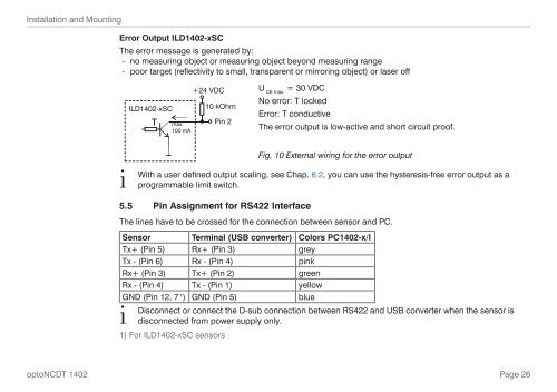
Installation and MountingError Output ILD<strong>1402</strong>-xSCThe error message is generated by:--no measuring object or measuring object beyond measuring range--poor target (reflectivity to small, transparent or mirroring object) or laser offILD<strong>1402</strong>-xSCTmax.100 mA+24 VDC10 kOhmPin 2U = 30 VDCCE max.No error: T lockedError: T conductiveThe error output is low-active and short circuit proof.iFig. 10 External wiring for the error outputWith a user defined output scaling, see Chap. 6.2, you can use the hysteresis-free error output as aprogrammable limit switch.5.5 Pin Assignment for RS422 InterfaceThe lines have to be crossed for the connection between sensor and PC.Sensor Terminal (USB converter) Colors PC<strong>1402</strong>-x/ITx+ (Pin 5) Rx+ (Pin 3) greyTx - (Pin 6) Rx - (Pin 4) pinkRx+ (Pin 3) Tx+ (Pin 2) greenRx - (Pin 4) Tx - (Pin 1) yellowGND (Pin 12, 7 1 ) GND (Pin 5)blueiDisconnect or connect the D-sub connection between RS422 and USB converter when the sensor isdisconnected from power supply only.1) For ILD<strong>1402</strong>-xSC sensors<strong>optoNCDT</strong> <strong>1402</strong>Page 26