Manual optoNCDT 1402 - Micro-Epsilon
Manual optoNCDT 1402 - Micro-Epsilon
Manual optoNCDT 1402 - Micro-Epsilon

You also want an ePaper? Increase the reach of your titles
YUMPU automatically turns print PDFs into web optimized ePapers that Google loves.
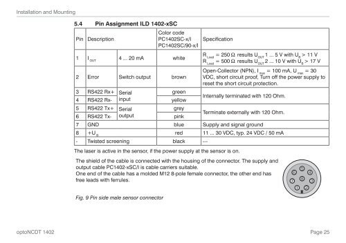
Installation and Mounting5.4 Pin Assignment ILD <strong>1402</strong>-xSCPinDescriptionColor codePC<strong>1402</strong>SC-x/IPC<strong>1402</strong>SC/90-x/I1 IOUT4 ... 20 mA whiteSpecificationRLoad = 250 W results U OUT 1 ... 5 V with U B > 11 VRLoad = 500 W results U OUT 2 ... 10 V with U B > 17 V2 Error Switch output brownOpen-Collector (NPN), I = 100 mA, U = 30max maxVDC, short circuit proof, Turn off the power supply toreset the short circuit protection.3 RS422 Rx+ Serialgreen4 RS422 Rx- inputyellowInternally terminated with 120 Ohm.5 RS422 Tx+ Serialgrey6 RS422 Tx- outputpinkTerminate externally with 120 Ohm.7 GND blue Supply and signal ground8 +UBred 11 ... 30 VDC, typ. 24 VDC / 50 mA- Twisted screening black ---The laser is active in the sensor, if the power supply at the sensor is on.The shield of the cable is connected with the housing of the connector. The supply andoutput cable PC<strong>1402</strong>-xSC/I is cable carriers suitable.One end of the cable has a molded M12 8-pole female connector, the other end hasfree leads with ferrules.Fig. 9 Pin side male sensor connector76581 243<strong>optoNCDT</strong> <strong>1402</strong>Page 25