Instruction manual colorSENSOR LT-1-LC-20 (PDF ... - Micro-Epsilon
Instruction manual colorSENSOR LT-1-LC-20 (PDF ... - Micro-Epsilon
Instruction manual colorSENSOR LT-1-LC-20 (PDF ... - Micro-Epsilon

Create successful ePaper yourself
Turn your PDF publications into a flip-book with our unique Google optimized e-Paper software.
<strong>Instruction</strong> Manual<br />
<strong>colorSENSOR</strong> <strong>LT</strong>-1-<strong>LC</strong>-<strong>20</strong>
Compact color sensor<br />
MICRO-EPSILON Eltrotec GmbH<br />
Heinckelstraße 2<br />
D-73066 Uhingen / Germany<br />
Tel. +49/7161/98872-300<br />
Fax +49/7161/98872-303<br />
e-mail eltrotec@micro-epsilon.de<br />
www.micro-epsilon.com<br />
Certified acc. to DIN EN ISO 9001: <strong>20</strong>08
<strong>colorSENSOR</strong> <strong>LT</strong>-1 Series • True Color Sensors<br />
<strong>Instruction</strong> Manual <strong>colorSENSOR</strong> <strong>LT</strong>-1-<strong>LC</strong>-<strong>20</strong><br />
<strong>colorSENSOR</strong> <strong>LT</strong> Series<br />
<strong>colorSENSOR</strong> <strong>LT</strong>-1-<strong>LC</strong>-<strong>20</strong><br />
- Big working range: typ. 1 mm ... 500 mm<br />
(depends on the fiber optics used and attachment optics)<br />
- Big assortment of fiber optics available (reflected light or<br />
transmitted light operation)<br />
- Up to 31 colors can be stored<br />
- RS232 interface (USB adapter is available)<br />
- Super-bright white light LED (AC-, DC-, PULSE-operation<br />
can be switched or OFF in case of luminous objects)<br />
- Color detection, contrast detection and grey scale detection<br />
- Insensitive to outside light<br />
- Brightness control can be activated<br />
- Switching frequency up to 35 kHz<br />
- TEACH via PC or external input<br />
- Various evaluation algorithms can be activated<br />
- Averaging’ can be activated (from 1 up to over 3<strong>20</strong>00 values)<br />
- Color control of luminous objects (LEDs, halogen lamps,<br />
displays, ...)<br />
- “BEST HIT“ mode (“human color assessment“)<br />
- 3-color filter detector (true color detector: “human color perception“)<br />
- Temperature compensated based on empirical values<br />
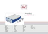
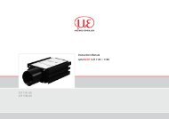
Design<br />
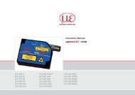
Product name:<br />
<strong>colorSENSOR</strong> <strong>LT</strong>-1-<strong>LC</strong>-<strong>20</strong><br />
(incl. software colorCONTROL-S<br />
Accessories: (cf. p. 8)<br />
Attachment optics<br />
Mounting<br />
possibilities<br />
Fiber optics adaptor<br />
for connection of<br />
fiber optics of LWL Series<br />
(cf. separate data sheet)<br />
Sturdy aluminum housing,<br />
anodized in black<br />
8-pole fem. connector Binder<br />
Series 712<br />
(connection to P<strong>LC</strong>)<br />
Connecting cable:<br />
CAB-M9-8P-St-ge; xm-PUR; open<br />
4-pole fem. connector Binder<br />
Series 707<br />
(RS232 interface)<br />
Connecting cable:<br />
CAB-M5-4P-St-ge; xm-PUR; RS232<br />
CAB-M5-4P-St-ge; xm-PVC; USB<br />
Mounting<br />
possibilities<br />
(threaded M4)<br />
Page 1
<strong>colorSENSOR</strong> <strong>LT</strong>-1 Series • True Color Sensors<br />
<strong>Instruction</strong> Manual <strong>colorSENSOR</strong> <strong>LT</strong>-1-<strong>LC</strong>-<strong>20</strong><br />
Technical Data<br />
Type<br />
<strong>LT</strong>-1-<strong>LC</strong>-<strong>20</strong><br />
Article number 10234060<br />
Object distance<br />
Dependent on the optical fibers used and the optical heads<br />
Reflex mode fiber optical cables typically 2 mm-15 mm with lens, typically 5 mm -100 mm 1)<br />
Light spot diameter<br />
Dependent on the optical fibers used and the optical heads<br />
Reflex mode fiber optical cables, typically Ø 0.6 mm-<strong>20</strong> mm 1)<br />
Color difference<br />
<br />
Color spaces<br />
X/Y INT; s/i M (Lab)<br />
Averaging<br />
More than max. 32768 values<br />
Size of the color<br />
memory<br />
<br />
Switching frequency Max. 35 kHz (depending on number of colors being taught and the setting for the averaging)<br />
Reproducibility In the x,y color range, 1 digit each with 12-Bit-A/D conversion<br />
Temperature drift X,Y<br />
< 0.01% K<br />
Light source<br />
jects,<br />
software-switchable)<br />
Type of illumination<br />
Via optical fiber<br />
<br />
illumination<br />
Suitable for flexibility<br />
Ambient light<br />
<br />
Intermittent light<br />
operation<br />
AC: typ. to <strong>20</strong> kHz<br />
<br />
<br />
+24 VDC (± 10 %), inverse polarity protected, overload-proof<br />
Current consumption<br />
< 160 mA<br />
Max. switching current<br />
100mA, short-circuit protected<br />
<br />
No button for external teaching of the color references apart from IN0<br />
Outputs<br />
<br />
pnp-capable<br />
(bright or dark switching, switchable)<br />
Switching state<br />
display<br />
-<br />
Interface<br />
RS232<br />
Type of connector<br />
<br />
<br />
Connection cable<br />
<br />
Receiver<br />
<br />
Software<br />
colorCONTROL S<br />
Adjustable 0 ms-100 ms<br />
Signal amplification<br />
<br />
Housing material<br />
Aluminium, black anodised<br />
Operating<br />
temperature<br />
-<strong>20</strong> °C - +55 °C<br />
Storage temperature -<strong>20</strong> °C - +85 °C<br />
<br />
<br />
<br />
<br />
Optical fiber<br />
See color catalog, page 34 onwards<br />
1)<br />
<br />
<br />
Page 2
<strong>colorSENSOR</strong> <strong>LT</strong>-1 Series • True Color Sensors<br />
<strong>Instruction</strong> Manual <strong>colorSENSOR</strong> <strong>LT</strong>-1-<strong>LC</strong>-<strong>20</strong><br />
Dimensions<br />
All dimensions in mm<br />
Page 3
<strong>colorSENSOR</strong> <strong>LT</strong>-1 Series • True Color Sensors<br />
<strong>Instruction</strong> Manual <strong>colorSENSOR</strong> <strong>LT</strong>-1-<strong>LC</strong>-<strong>20</strong><br />
Connector Assignment<br />
Connection to P<strong>LC</strong>:<br />
8-pole fem. connector Binder Series 712<br />
Pin: Color: Assignment:<br />
1 white GND (0V)<br />
2 brown +24VDC (±10%)<br />
3 green IN0<br />
4 yellow OUT0<br />
5 grey OUT1<br />
6 pink OUT2<br />
7 blue OUT3<br />
8 red OUT4<br />
Connecting cable to P<strong>LC</strong>:<br />
CAB-M9-8P-St-ge; xm-PUR; open<br />
Connecting cable:<br />
CAB-M9-8P-St-ge: 2m-PUR; open<br />
CAB-M9-8P-St-ge: 5m-PUR; open<br />
(Standard length 2 m)<br />
Connection to PC:<br />
4-pole fem. connector Binder Series 707<br />
Pin:<br />
Assignment:<br />
1 +24VDC (+Ub, OUT)<br />
2 GND (0V)<br />
3 RxD<br />
4 TxD<br />
Connecting cable:<br />
CAB-M5-4P-St-ge; 2m-PUR; RS232<br />
CAB-M5-4P-St-ge; 5m-PUR; RS232<br />
(Standard length 2 m)<br />
alternatively:<br />
Connecting cable (incl. driver software):<br />
CAB-M5-4P-St-ge; 2m-PVC; USB<br />
CAB-M5-4P-St-ge; 5m-PVC; USB<br />
(Standard length 2 m)<br />
Connecting cable to PC (RS232 interface):<br />
CAB-M5-4P-St-ge; xm-PUR; RS232<br />
Connecting cable to PC (USB interface):<br />
CAB-M5-4P-St-ge; xm-PVC; USB<br />
(incl. driver software)<br />
Page 4
<strong>colorSENSOR</strong> <strong>LT</strong>-1 Series • True Color Sensors<br />
<strong>Instruction</strong> Manual <strong>colorSENSOR</strong> <strong>LT</strong>-1-<strong>LC</strong>-<strong>20</strong><br />
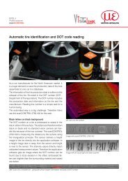
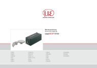
Measuring Principle<br />
Measuring principle of the color sensors of <strong>colorSENSOR</strong> <strong>LT</strong>-1 series:<br />
The <strong>colorSENSOR</strong> <strong>LT</strong>-1 provides highly flexible signal acquisition. For example, the sensor can be operated in alternating-light<br />
mode (AC mode), which makes the sensor insensitive to extraneous light. It also can be set to constant-light mode (DC mode),<br />
which makes the sensor extremely fast and allows a scan-frequency of up to 35 kHz.<br />
An OFF function turns off the integrated light source at the sensor and changes to DC operation. The sensor then can detect socalled<br />
"self-luminous objects". In PULSE operation extremely dark surfaces can be reliably detected. With the stepless<br />
adjustment of the integrated light source and the selectable gain of the receiver signal the sensor can be set to almost any<br />
surface or any "self-luminous object".<br />
When the integrated light source of the <strong>colorSENSOR</strong> <strong>LT</strong>-1 color sensor is activated, the sensor detects the radiation that is<br />
diffusely reflected from the object. As a light source the <strong>colorSENSOR</strong> <strong>LT</strong>-1 color sensor uses a white-light LED with adjustable<br />
transmitter power. An integrated 3-fold receiver for the red, green, and blue content of the light that is reflected from the object, or<br />
the light that is emitted by a "self-luminous object", is used as a receiver. As mentioned above, a special feature here is that the<br />
gain of the receiver can be set in 8 steps. This makes it possible to optimally adjust the sensor to almost any surface and to<br />
different "self-luminous objects".<br />
The <strong>colorSENSOR</strong> <strong>LT</strong>-1 color sensor can be "taught" up to 31 colors. For each of these taught colors it is possible to set<br />
tolerances.<br />
In X/Y INT or s/i M mode these tolerances form a color cylinder in space. In X/Y/INT or s/i/M mode the tolerances form a color<br />
sphere in space. Color evaluation according to s/i M is based on the lab calculation method. All modes can be used in<br />
combination with several operating modes such as "FIRST HIT" and "BEST HIT". Raw data are represented with 12 bit resolution.<br />
Color detection either operates continuously or is started through an external P<strong>LC</strong> trigger signal.<br />
The respective detected color either is provided as a binary code at the 5 digital outputs or can be sent directly to the outputs, if<br />
only up to 5 colors are to be detected. [Please note: Visualisation by means of LEDs not available with <strong>colorSENSOR</strong> <strong>LT</strong>-1-<strong>LC</strong>-<strong>20</strong>]<br />
Parameters and measurement values can be exchanged between a PC and the <strong>colorSENSOR</strong> <strong>LT</strong>-1 color sensor through the<br />
serial RS232 interface. All the parameters for color detection also can be saved to the non-volatile EEPROM of the <strong>colorSENSOR</strong><br />
<strong>LT</strong>-1color sensor through this serial RS232 interface. When parameterisation is finished, the color sensor continues to operate<br />
with the current parameters in STAND-ALONE mode without a PC.<br />
The sensors of the <strong>colorSENSOR</strong> <strong>LT</strong>-1 series can be calibrated (white-light balancing). Balancing can be performed to any white<br />
surface. A ColorCheckerTM table with 24 color fields is available as an alternative.<br />
Page 5
<strong>colorSENSOR</strong> <strong>LT</strong>-1 Series • True Color Sensors<br />
<strong>Instruction</strong> Manual <strong>colorSENSOR</strong> <strong>LT</strong>-1-<strong>LC</strong>-<strong>20</strong><br />
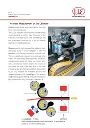
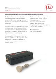
Diagrams<br />
Diagrams:<br />
SPOT DIAMETER<br />
depending on distance<br />
SPOT DIAMETER [distance], typ.<br />
Spot diameter / Spotdurchmesser<br />
[mm]<br />
<strong>colorSENSOR</strong> <strong>LT</strong>-1-<strong>LC</strong>-<strong>20</strong><br />
0,4<br />
with fiber opticsFAR-T-A1.1-1,5-1<strong>20</strong>0-67°<br />
0,2<br />
and attachment optics KL-4<br />
(fiber optics fixed at limit stop into attachment optics) 0<br />
2,4<br />
2,2<br />
2<br />
1,8<br />
1,6<br />
1,4<br />
1,2<br />
1<br />
0,8<br />
0,6<br />
6 8 10 12 14 16<br />
Distance / Abstand [mm]<br />
Fiber bundle Ø 2.5 mm<br />
SPOT DIAMETER [distance], typ.<br />
<strong>colorSENSOR</strong> <strong>LT</strong>-1-<strong>LC</strong>-<strong>20</strong><br />
with fiber optics FAR-T-A2.0-2,5-600-67°<br />
Spot diameter / Spotdurchmesser<br />
[mm]<br />
10<br />
9<br />
8<br />
7<br />
6<br />
5<br />
4<br />
3<br />
2<br />
1<br />
0<br />
0 2 4 6 8 10 12 14 16 18 <strong>20</strong> 22 24 26<br />
Distance / Abstand [mm]<br />
3,5<br />
SPOT DIAMETER [distance], typ.<br />
Spot diameter / Spotdurchmesser<br />
[mm]<br />
<strong>colorSENSOR</strong> <strong>LT</strong>-1-<strong>LC</strong>-<strong>20</strong><br />
with fiber optics FAR-T-A2.0-2,5-1<strong>20</strong>0-67°<br />
0,5<br />
and attachment optics KL-3<br />
(fiber optics fixed at limit stop into attachment optics) 0<br />
3<br />
2,5<br />
2<br />
1,5<br />
1<br />
6 7 8 9 10 11 12 13 14 15 16<br />
Distance / Abstand [mm]<br />
Page 6
<strong>colorSENSOR</strong> <strong>LT</strong>-1 Series • True Color Sensors<br />
<strong>Instruction</strong> Manual <strong>colorSENSOR</strong> <strong>LT</strong>-1-<strong>LC</strong>-<strong>20</strong><br />
Diagrams:<br />
Diagrams<br />
SPOT DIAMETER<br />
depending on distance<br />
SPOT DIAMETER [distance], typ.<br />
Spot diameter / Spotdurchmesser<br />
[mm]<br />
<strong>colorSENSOR</strong> <strong>LT</strong>-1-<strong>LC</strong>-<strong>20</strong><br />
2<br />
with fiber optics FAR-T-A2.0-2,5-1<strong>20</strong>0-67°<br />
and attachment optics KL-M18-A2.0<br />
1<br />
(fiber optics fixed at limit stop into attachment optics) 0<br />
10<br />
9<br />
8<br />
7<br />
6<br />
5<br />
4<br />
3<br />
10 15 <strong>20</strong> 25 30 35 40 45 50 55 60<br />
Distance / Abstand [mm]<br />
SPOT DIAMETER [distance], typ.<br />
<strong>colorSENSOR</strong> <strong>LT</strong>-1-<strong>LC</strong>-<strong>20</strong><br />
with fiber optics FAR-T-A2.0-2,5-1<strong>20</strong>0-67°<br />
and attachment optics KL-M34-A2.0<br />
(fiber optics fixed at limit stop into attachment optics)<br />
Spot diameter / Spotdurchmesser<br />
[mm]<br />
<strong>20</strong><br />
19<br />
18<br />
17<br />
16<br />
15<br />
14<br />
13<br />
12<br />
11<br />
10<br />
9<br />
8<br />
40 60 80 100 1<strong>20</strong> 140 160 180 <strong>20</strong>0 2<strong>20</strong><br />
Distance / Abstand [mm]<br />
SPOT DIAMETER [distance], typ.<br />
short semiaxis<br />
long semiaxis<br />
Fiber gap 6 mm x 1 mm<br />
<strong>colorSENSOR</strong> <strong>LT</strong>-1-<strong>LC</strong>-<strong>20</strong><br />
with fiber optics FAR-T-R2.1-6x1-1<strong>20</strong>0-67°<br />
Spot diameter / Spotdurchmesser<br />
[mm]<br />
12<br />
11<br />
10<br />
9<br />
8<br />
7<br />
6<br />
5<br />
4<br />
3<br />
2<br />
1<br />
0<br />
0 2 4 6 8 10 12 14 16 18 <strong>20</strong> 22 24 26<br />
Distance / Abstand [mm]<br />
Page 7
<strong>colorSENSOR</strong> <strong>LT</strong>-1 Series • True Color Sensors<br />
<strong>Instruction</strong> Manual <strong>colorSENSOR</strong> <strong>LT</strong>-1-<strong>LC</strong>-<strong>20</strong><br />
Attachment Optics<br />
Type<br />
Article<br />
number<br />
Object distance<br />
(typ.)<br />
Detection range<br />
(typ.)*<br />
Dimensions<br />
LWL<br />
FASOP<br />
KL-3 10823012 8mm - <strong>20</strong>mm 1mm - 5mm<br />
L x Ø<br />
ap. 60mm x 15mm<br />
A 2.0 1)<br />
KL-M18-A2.0 108230<strong>20</strong> 15mm - 50mm 2mm - 10mm<br />
L x Ø<br />
ap. 51mm x M18 x 1<br />
A 2.0 1)<br />
KL-M34 10823278 80mm - 150 mm 10mm - <strong>20</strong>mm<br />
L x Ø<br />
ap. 71mm x M34 x 1.5<br />
A 2.0 1)<br />
KL-M34/62 10824196 80mm - 150 mm 2mm - 5mm<br />
L x Ø<br />
ap. 170mm x 62mm<br />
A 2.0 1)<br />
KL-4 10823262 8mm - <strong>20</strong>mm 0.6mm - 3mm<br />
L x Ø<br />
ap. 60mm x 15mm<br />
A 1.1 1)<br />
KL-M18-A1.1 10824140 10mm - 50mm 2mm - 7mm<br />
L x Ø<br />
ap. 51mm x M18 x 1<br />
A 1.1 1)<br />
KL-D-40 10824143 15mm - 25mm 3mm - 5mm<br />
L x W x H<br />
ap. 43.4 x 49.5 x 12mm<br />
A 2.0 2)<br />
KL-D-28 10824197 <strong>20</strong>mm - 30mm 5mm - 8mm<br />
L x W x H<br />
ap. 31.7 x 40.5 x 15mm<br />
A 2.0 2)<br />
KL-D-<strong>20</strong> 10823021 <strong>20</strong>mm - 40mm 4mm - 10mm<br />
L x W x H<br />
ap. 21.4 x 33 x 12mm<br />
A 2.0 2)<br />
Kl-D-17 108232<strong>20</strong> 30mm - 80mm 8mm - 25mm<br />
L x W x H<br />
ap. 36.5 x 25.5 x 15mm<br />
A 2.0 2)<br />
KL-D-14 10823022 60mm - 1<strong>20</strong>mm 10mm - <strong>20</strong>mm<br />
L x W x H<br />
ap. 37 x 50 x <strong>20</strong>mm<br />
A 2.0 2)<br />
KL-D-6 10823409 100mm - <strong>20</strong>0mm 15mm - 30mm<br />
L x W x H<br />
ap. 31.1 x 45.1 x <strong>20</strong>mm<br />
A 2.0 2)<br />
KL-5 10824198 8mm - <strong>20</strong>mm<br />
2mm x 0.3mm<br />
to 15mm x 3mm<br />
L x Ø<br />
ap. 60mm x 15mm<br />
R 1.1 1)<br />
KL-8 108239<strong>20</strong> 8mm - <strong>20</strong>mm<br />
4mm x 0.7mm<br />
to 30mm x 5mm<br />
L x Ø<br />
ap. 60mm x 15mm<br />
R 2.1 1)<br />
* The smallest figure in the table relates to the smallest typical optical diameter that is generated.<br />
This corrresponds to roughly the smallest detection area for color or optical fiber sensors.<br />
1) Reflex optical fiber (FAR)<br />
2) Transmitted light mode fiber optical cables (FAD)<br />
Page 8
MICRO-EPSILON Eltrotec GmbH<br />
Heinkelstraße 2 · 73066 Uhingen / Germany<br />
Tel. +49 (0) 7161 / 98872-300 · Fax +49 (0) 7161 / 98872-303<br />
eltrotec@micro-epsilon.de · www.micro-epsilon.com<br />
X9751274-A021032HDR<br />
*X9750274-A02*