Rubber and Tire Inspection (PDF, 1.87 MB) - Micro-Epsilon
Rubber and Tire Inspection (PDF, 1.87 MB) - Micro-Epsilon
Rubber and Tire Inspection (PDF, 1.87 MB) - Micro-Epsilon
- No tags were found...

You also want an ePaper? Increase the reach of your titles
YUMPU automatically turns print PDFs into web optimized ePapers that Google loves.
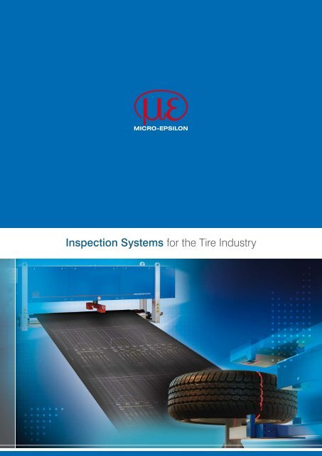
<strong>Inspection</strong> Systems for the <strong>Tire</strong> Industry
2References (extract)<strong>Tire</strong> Component Profilometer TCP 8302.T /LLT Page 4 - 5<strong>Tire</strong> ComponentOffline Profilometer TCP 8302.T-Offline Page 6 - 7<strong>Tire</strong> Component Profilometer TCP 8301.EO Page 8 - 9<strong>Tire</strong> Component Profilometer TCP 8301.CT /CLLT Page 10 - 11<strong>Tire</strong> Component Profilometer TCP 8301.I Page 12 - 13<strong>Tire</strong> Color <strong>Inspection</strong> TCI 8303.I Page 14 - 15<strong>Tire</strong> Length <strong>Inspection</strong> TLI 8303.I Page 16 - 17<strong>Tire</strong> Piece Weight <strong>Inspection</strong> TWI 8302.C-TT Page 18 - 19<strong>Tire</strong> Geometry <strong>Inspection</strong> TGI 8302.LLT Page 22 - 23<strong>Tire</strong> Mark <strong>Inspection</strong> TMI 8301.I Page 24 - 25<strong>Tire</strong> Identity/DOT <strong>Inspection</strong> TID/TDI 8300.I Page 26 - 27Retrofit <strong>Tire</strong> Geometry <strong>Inspection</strong> RTG Page 28Retrofit of <strong>Tire</strong> Uniformity Line RTU Page 29Retrofit of Balancing Line RTB Page 30
3Overview Preparation Area<strong>Tire</strong> Component ProfilometerthicknessCONTROL TCP 8302.T/LLTPage 4-5<strong>Tire</strong> Component ProfilometerthicknessCONTROL TCP 8301.IPage 12-13<strong>Tire</strong> Component Offline ProfilometerthicknessCONTROL TCP 8302.T -OfflinePage 6-7<strong>Tire</strong> Color <strong>Inspection</strong>dimensionCONTROL TCI 8303.IPage 14-15<strong>Tire</strong> Component ProfilometerthicknessCONTROL TCP 8301.EOPage 8-9<strong>Tire</strong> Length <strong>Inspection</strong>dimensionCONTROL TLI 8303.IPage 16-17<strong>Tire</strong> Component ProfilometerthicknessCONTROL TCP 8301.CT/CLLTPage 10-11<strong>Tire</strong> Piece Weight <strong>Inspection</strong>dimensionCONTROL TWI 8302.C.TTPage 18-19
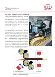
4<strong>Tire</strong> Component ProfilometerthicknessCONTROL TCP 8302.T/LLTInstallation sites & possible applicationsThickness profile measurement in- B<strong>and</strong>ing lines- Small extrusion linesThickness measurement of sqezze ininner liner applicationsThe modularly designed, C-frame based systemsof the thicknessCONTROL TCP 8302series convincedue to their flexibility <strong>and</strong> performancein the long term. Their compact designenables to introduce precise inspection technologyalso in lines with low packaging space.High data volumeIn the upper <strong>and</strong> lower flange of the C-frame,either laser triangulation point (ILD) or lasertriangulation line (LLT) sensors are integrated.The result, showing the profile of the targetmaterial is calculated with the difference of theadded amount of the sensor signals <strong>and</strong> the calibratedworking gap. In combination with highly-efficientsignal processing algorithms of theanalysis <strong>and</strong> visualization software, accuraciesin the micrometer range are reached.A fully-automatic in-situ calibration ensures themeasurement to be independent from temperatureinfluences, thus the system can be appliedin harsh industrial environments beingcharacterized by permanently providing inlineprecision. The sensor technologies measurewithout contact, wear-free <strong>and</strong> without isotopesor X-rays. This process provides long-term reliablemeasurement results while avoiding consequentialcosts.Using integrated laser line sensors, generatinga high data volume of 128.000 data points persecond, the thicknessCONTROL TCP 8302.LLToffers a unique range of solvable applicationsregarding profile thickness measurement in thetire industry.TCP8302.LLTLaserline triangulationTCP8302.LLaser triangulationTraversing measurement of cross profile
5thicknessCONTROL TCP 8302.T/LLTDescription -20/500 -50/500 -20/800 -50/800 -25/500 -50/500 -25/800 -50/800Article No. 4350127.230 4350127.231 4350127.232 4350127.233 4350127.234 4350127.235 4350127.236 4350127.237Sensor Laser Point Sensor Laser Line SensorLaser class2MMeasuring width 500mm 500mm 800mm 800mm 500mm 500mm 800mm 800mmWorking gap 70mm 156mm 70mm 156 mm 190mm 420mm 190mm 420mmNominal measuring gap 20mm 50mm 20mm 50mm 25mm 50mm 25mm 50mmMeasuring gap max 20mm 50mm 20mm 50mm 40mm 100mm 40mm 100mmStart of measuring gap 410mm 415mm 410mm 415mm 306mm 391mm 306mm 391mmLinearity nom. MG±6µm ±15µm ±6µm ±15µm ±5µm ±10µm ±5µm ±10µm±0.3% ±0.4%Sampling rate max 20kHz 128kHzDimensions in mm 973 x 168 x 635* 973 x 168 x 665* 1273 x 168 x 635* 1273 x 168 x 665* 818 x 204 x 601* 818 x 204 x 831* 1028 x 204 x 601* 1018 x 204 x 831*WeightProtection classapprox. 80kg packaging includedIP54 (higher on request)Ambient temperature min. + 15 °C max. + 40 °CMG = measuring gap*=length without linear axis190total widthtotal heigthstart measuring gapworking gapmeasuring gapdepthmeasuring widthExample for thicknessCONTROL TCP 8302.LLT
6<strong>Tire</strong> Component Offline ProfilometerthicknessCONTROL TCP 8302.T-OfflineInstallation sites & possible applicationsThickness <strong>and</strong> width profile measurement in- Extrusion lines- Innerliner calender- Ply calender- Steel cord calender- Textile or Fabric cord calenderWith the thickness CONTROL TCP 8302.T-Offline, a line independent tool measuring theprofile thickness <strong>and</strong> width is available. Multiplelines can be controlled semi-automatically <strong>and</strong>very cost-effectively.Improving qualitiy controlAn integrated, traversing C-Frame with twooptical laser triangulation sensors carries outthe inspection of the entire profile. The systemcontains fully automated, integrated calibrations.The process of the calibration <strong>and</strong> controlmeasurement takes approximately 10 seconds.The visualization software of the profilometercontains tools for statistic processing of measuredprofile results <strong>and</strong> for exporting measurementresults in different formats for furtherprocessing. The measurement system is fullycovered; therefore the influence of external lighton the measurement process <strong>and</strong> the creationof parasitic reflections is minimized. This is acost-effective solution of profile measurementsperformed outside the line.Cross profile - single inspectionCross profile - parallel inspectionRecipe editor
7thicknessCONTROL TCP 8302.T-OfflineDescription -10/600 -10/800 -10/1000Article No. 4350142.01 4350142.02 4350142.03Laser classMeasuring rangeMaterial range2MMax. thickness50mmMax. width 600mm 800mm 1000mmMax. thickness47mmMax. width 580mm 780mm 980mmMax. material tilt 80°Linearity nom. MRResolutionMeasurement speedMeasurement rateThicknessWidthThicknessWidth±10μm±50μm1μm10μm10mm/s20kHzCommunication with the master systemEthernet - UDP or TCP/IP protocollDimensions (L x W x H) in mm 1050 x 800 x1 800 1200 x 800 x 1800 1450 x 800 x 1800Weight app. (exclusive transport case) 400kg 450kg 500kgProtection classIP42Ambient temperature min. +15 °C max. +40 °CRelative air humidityMR = measuring rangemax. 75 % in declared temperature without condensationLWML
8<strong>Tire</strong> Component ProfilometerthicknessCONTROL TCP 8301.EOInstallation sites & possible applicationsThickness profile measurement in:- Extrusion lines- Innerliner calender- Ply calender- Textile or Fabric cord calenderThe thicknessCONTROL TCP 8301.EO family ismanufactured as O-frame <strong>and</strong> significantly impressesby large material width <strong>and</strong> stability aswell as high precision during thickness profilemeasurements.Application-specific sensorsThe system measures differentially i.e. the thicknessof the material is calculated from two distancesignals. The combination of an eddy currentsensor <strong>and</strong> a Thru-Beam sensor is appliedon one side of the thicknessCONTROL TCP8301.EO whereat the material is guided overa measuring roller. The thickness of the targetmaterial is the difference between the sensorsto each other <strong>and</strong> the amount of signals.With the color-independent functioning of theintegrated Thru-Beam sensor, measuring theupper edge of the rubber, the system suppliesresults in extraordinary precision. It is alsoequipped with an efficient cleaning mechanismproviding high resistance against steam<strong>and</strong> particles. Therefore, the system ideal forapplications in harsh industrial environments.Furthermore it offers efficient operation facilitiesdue to large maintenance-free intervals.Using application-specific customized sensorsthe thicknessCONTROL TCP 8301.EO is,amongst other things, impressive due to its excellentratio of measuring range.Set-up mode sensors <strong>and</strong> system control Longitudinal trend for 5 tracks TCP 8301.EO Thickness measurement with TCP 8301.EO
9thicknessCONTROL TCP 8301.EODescription -10/1000 -10/1500 -10/2000 -10/2500 -10/3000 -10/3500 -10/4000Article No. 4.350.039.100 4.350.039.101 4.350.039.102 4.350.039.103 4.350.039.104 4.350.039.105 4.350.039.106Light sourcered LEDTraversing width (gross width) 1200mm 1700mm 2200mm 2700mm 3200mm 3700mm 4200mmMaterial width max (net width) 1000mm 1500mm 2000mm 2500mm 3000mm 3500mm 4000mmThreading gapMeasuring gapMeasuring range max.100mm12mm10mmLinearity in % nom. MR 0.06 % *Linearity nom. MR ±3µm *Roll diameter≤200mmB<strong>and</strong> angle >60°Sampling rate max.Traversing speedLateral spatial resolution≤4kHz6000 to 15000 mm/min0.025mmDimensions (L x W x H) in mm 2000 x 500 x 900 2500 x 500 x 900 3000 x 500 x 900 3500 x 500 x 900 4000 x 500 x 900 4500 x 500 x 900 5000 x 500 x 900Protection classAmbient temperatureIP54min. +15°C max. +40°CRelative air humidity75% max. within temperature range stipulated without condensationMR = measuring range * in relation to st<strong>and</strong>ard roll (higher linearity can be achieved using special rolls)5005001188.51188.589089034034077.2077.20Ø200Ø200552552250170100250170 01000012.5100017012.5250100170250552552
10<strong>Tire</strong> Component ProfilometerthicknessCONTROL TCP 8301.CT/CLLTInstallation sites & possible applicationsThickness profile measurement in- Extrusion lines- Innerliner calender- Ply calender- Steel cord calender- Textile or Fabric cord calenderThe systems of the thicknessCONTROL TCP8301.CT/CLLT family are developed in form ofan O-frame where the sensors are integrated inthe upper <strong>and</strong> the lower boom. They work whiletraversing <strong>and</strong> succeed through an innovativecoordinated package consisting in sensors,mechanics <strong>and</strong> software.Closed-loop temperature compensationThe systems measure differentially i.e. thethickness of the material is calculated from twodisplacement signals. Two sensors are integratedon the upper <strong>and</strong> lower boom of the O-frameon a mechanical carriage. The thickness of thetarget material is the displacement betweenthe sensors to each other <strong>and</strong> the amount ofsignals.Offering an efficient cleaning mechanism,high resistance against steam <strong>and</strong> particles isprovided. Therefore, the devices are ideal forapplications in harsh industrial environments.Furthermore, they offer efficient operation facilitiesdue to large maintenance-free intervals.Thanks to integrated in-situ calibrations whichdo not vary with temperature, they can be alsoapplied under harsh climate environmental conditionse.g. in the rubber processing industry.All sensor technologies applied measure withoutcontact, wear-free <strong>and</strong> without isotopes orX-rays. This process provides long-term reliablemeasured data while avoiding consequentialcosts.Using a patented closed-loop concept forcompensation of temperature driven parasiticeffects on the mechanics, the thicknessCON-TROL TCP 8301.CT <strong>and</strong> thicknessCONTROLTCP 8301.CLLT present a revolutionary stabilityin the production.thickness measurement with TCP 8301.TCombination profile8301.CT; vertical cursors showthe points which are used for calender control
11thicknessCONTROL TCP 8301.CT/CLLTDescription -20/700 -20/1200 -20/1700 -20/2200 -20/2700 -20/3200Article No. 4350133.100 4350133.101 4350133.102 4350133.103 4350133.104 4350133.105Light sourceLaser class 2MTraversing width 750mm 1250mm 1750mm 2250mm 2750mm 3250 mmMaterial width max. (net width) 700mm 1200mm 1700mm 2200mm 2700mm 3200 mmThreading gapMeasuring gapMeasuring range max.Linearity in % nom. MRLinearity nom. MRSampling rate max.Traversing speedLateral spatial resolution400mm70mm20mm0.1% FSO±10µm≤4kHz6,000 bis 15,000mm/min0.025mmDimensions (L x W x H) in mm 2000 x 585 x 1869.4 2500 x 585 x 1869.4 3000 x 585 x 1869.4 3500 x 585 x 1869.4 4000 x 585 x 1869.4 4500 x 585 x 1869.4Weight appr. 500kg 560kg 620kg 680kg 740kg 800kgProtection classAmbient temperatureRelative air humidityMR = measuring range FSO = Full Scale OutputIP20min. +15°C max. +40°C75% max. within temperature range (without condensation)LWH
12<strong>Tire</strong> Component ProfilometerthicknessCONTROL TCP 8301.IInstallation sites & possible applicationsThickness <strong>and</strong> width profile measurement in- Extrusion lines- Innerliner calender- Ply calender- Steel cord calender- Textile or Fabric cord calender- Cap stripe lineThe non-traversing profilometers of the thicknessCONTROLTCP 8301.I series enthuse withthe complete profile measurements in one singleshot. Working nearly without moving parts thesystems provide a solution at low maintenancerequirements.Prepared for additional controlBased on the optical triangulation principle twoparallel lines are projected by laser light sourcesonto the upper <strong>and</strong> the lower side of thematerial. The reflection of the laser light is detectedby cameras.The visualization software of the profilometercontains tools for statistic processing <strong>and</strong>exporting measurement results in differentformats. The measurement system is fully covered;therefore the influence of external lighton the measurement process <strong>and</strong> the creationof parasitic reflections is minimized.Prepared for additional integration of the lengthinspection dimensionCONTROL TLI 8303.I <strong>and</strong>the dimensionCONTROL TPI 8302.C.TT, theprofilo meter is the efficient base for a completequality control of an extrusion line.The measurement system contains fully automatedintegrated calibrations. The patentedprocess of the calibration takes approximately5 minutes.Integration:PWI 8302.C-TTTLI 8303.ITCP 8301.IProfile shape modeCross profile
13thicknessCONTROL TCP 8301.IDescription -10/170 -10/350 -10/450 -10/550 -20/550 -20/750 -20/860 -20/1220Article No. 4350121.105 4350121.106 4350121.107 4350121.108 4350121.101 4350121.102 4350121.104 4350121.103Laser classMeasuring rangeMaterial range2MMax. thickness 20mm 40mm 40mm 40mm 50mm 50mm 50mm 50mmMax. width 170mm 350mm 450mm 550mm 550mm 750mm 860mm 1200mmMax. thickness 15mm 35mm 35mm 35mm 45mm 45mm 45mm 45mmMax. width 150mm 330mm 430mm 530mm 530mm 730mm 860mm 1150mmMaterial fluctuationMax. thickness fl.Max. width fl.±2.5mm±10mmMax. material tilt 50°Linearity nom. MR*ResolutionThickness ±12μm ±12μm ±12μm ±12μm ±20μm ±20μm ±20μm ±20μmWidth ±100μm ±150μm ±150μm ±150μm ±200μm ±200μm ±200μm ±200μmThickness1μmWidth 10μm 20µmNumber of measurements per second 40Communication with the master systemDimensions (L x W x H in mm),adaptation possibleEthernet - UDP or TCP/IP protocoll1600 x 840 x 1650 1600 x 840 x 1650 1800 x 840 x 1650 2000 x 840 x 1650 2000 x 840 x 1650 2300 x 840 x 1650 2400 x 840 x1650 2500 x 840 x 1650Weight app. (exclusive transport case) 500kg 550kg 600kg 600kg 650kg 650kg 700kgProtection classIP42Ambient temperature min. +15 °C, max. +40 °CRelative air humidityMR = measuring range* Deviation 1 sigmamax. 75 % in declared temperature without condensationLWH
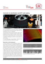
14<strong>Tire</strong> Color <strong>Inspection</strong>dimensionCONTROL TCI 8303.IInstallation sites & possible applicationsColor coding, color code inspection, widthmeasurement in- Extrusion lines for sidewall or treadThe <strong>Tire</strong> Color <strong>Inspection</strong> dimensionCONTROLTCI 8303.I provides fully equipped color coding,color code inspection <strong>and</strong> width inspection ofextruded tread, <strong>and</strong> therefore represents apower ful component of a modern extrusion line.The system detects overflow or interruptionof color strips <strong>and</strong> incorrect colors on definedpositions. It is covered as much as possible inorder to resist harsh environments especiallybehind the extruder head.Reducing wasteThe basic model of dimensionCONTROL TCI8303.I has been designed for inspection of colorcode applied on running profiles behind theextruder. Due to the fact that the correct widthposition of the color code has to be checked,the system measures also the complete widthof the tread. The inspection is implemented asvision system, containing one color camera <strong>and</strong>two surface light sources. The measurement iscontinuous; position <strong>and</strong> width of respectivecolors are calculated as an average value inone image.Beside the inspection, two different upgradesof dimensionCONTROL TCI 8303.I are availableenabling an automatic color application. In thefirst version the single color tracks have a fixeddistance to each other <strong>and</strong> a whole frame iscontrolled in relationship to the edge of profile.In the enhanced version every color track is controlledseparately with an own motion control.The performance of the system reduces thewaste material dramatically, compared to manualadjustment of tracks during recipe changingsor while starting the extrusion line.Principle of measurementVisualization of inspected color codeRecipe editor
15dimensionCONTROL TCI 8303.IDescription -350 -550Article No. 4350148.01 4350148.02Width measurement range 350mm 550mmMax. material speedMinimum width of color detected (mm)40m / min1mmSize of scanned image (width x length) 400x135mm 600x135mmNumber of color bottles 6Stroke of electrical axis (mm)Linearity nom. MR±200mm from middle of conveyor±150µmResolution 100µmNumber of measurements per second 20Communication with the master systemEthernet - UDP or TCP/IP protocollDimensions ( L x W x H) in mm 1400 x 1400 x 1800Weight app. (exclusive transport case)Protection classAmbient temperatureRelative air humidityMR = measuring range400kgIP42min. +15°C max. +65°Cmax. 75 % in declared temperature without condensationWLH
16<strong>Tire</strong> Length <strong>Inspection</strong>dimensionCONTROL TLI 8303.IInstallation sites & possible applicationsLength measurement in- Extrusion lines for sidewall or treadHighly efficient image processing algorithmsaward the dimensionCONTROL TLI 8303.I forprecisely mapping the needs of later processsteps in the tire building.Optimized process mappingThe vision system dimensionCONTROL TLI8303.I contains two cameras for profile lengthinspection in extrusion lines . The first camera ismounted on an electrical axis at the beginningof the profile - above the scale, the second isinstalled at the end of the profile.Depending on the concept it is either underthe rollers at the end of the scale or above thescale. The moveable camera is positioned accordingthe nominal length received from themaster of the extrusion line. The calculation ofthe profile length is based on the form of thecuts at each edge. To optimize the mapping ofthe inspection result <strong>and</strong> the real profile fit in thebuilding machine, the edges are connected virtuallyto each other according to the scannedsurfaces. Based on these values <strong>and</strong> the positionbetween the cameras the final length iscalculated.Principle of measurementVisualization of the cutted edges, the length <strong>and</strong> the widthIllumination for the upper side
17dimensionCONTROL TLI 8303.IDescription -1000(DU) -1000(UU) -2700(DU) -2700(UU)Article No. 4350149.02 4350149.03 4350149.04 4350149.05Position of camerasProfile lengthUp / DownMin. 1500mm 1500mm 1300mm 1300mmMax. 2500mm 2500mm 4000mm 4000mmThicknessEvaluation area of profile widthMax. material speedMin.Max.5mm50mm350mm110m / minLinearity nom. MR ±100µm ±200µm ±200µm ±300µmResolution 100µmMaximum material fluctuation(vertically to the flow of material)10mmMaximum material rotation(based on material flow)10mmCommunication with the master systemEthernet - UDP or TCP/IP protocollDimensions ( L x W x H ) in mm 1400 x 850 x 300 2700 x 850 x 300Weight app. (exclusive transport case) 180kg 250kgProtection classIP42Ambient temperature min. +15 °C max. +40 °CRelative air humidityMR = measuring rangemax. 75 % in declared temperature without condensationWL870381Material flow221ML318 572270310
18<strong>Tire</strong> Piece Weight <strong>Inspection</strong>dimensionCONTROL TWI 8302.C.TTInstallation sites & possible applicationsWeight measurement in- Extrusion line for sidewall or treadWhen taking a new direction by using displacementsensors, dimensionCONTROL TWI8302.C.TT st<strong>and</strong>s for extraordinary precision ininspecting running tread profiles for truck tires.Completing quality controlThe device is based on a steel C-frame, containingtwo highly precise capacitive sensors.The deflection of a steel beam is measured witha high sampling rate. The data processing ofthe obtained sensor values is implemented inan electronic system <strong>and</strong> the weight is determinedmathematically. The C-frame is attached toa massive construction, which ensures a longtermmechanical stability of the TWI 8302.C.TT.Covered in a high degree it resists harsh environmentsin the preparation area.The included software contains a wide range ofstatistic measurement processing, definition ofdesign profiles, statistical analysis of measuredprofiles <strong>and</strong> diagnostic tools. Together with thedimensionCONTROL TCI 8303.I, the dimensionCONTROLTLI 8303.I <strong>and</strong> the thicknessCON-TROL TCP 8301.I it allows the complete qualityassurance <strong>and</strong> also a closed loop control of theextrusion line.Integration:TWI 8302.C.TTTLI 8303.ITCP 8301.IVisualization of weight <strong>and</strong> width resultsDisplay fo SPC data
19dimensionCONTROL TWI 8302.C.TTDescription -3800Article No. 4350220Measuring rangeMaterial rangeMax. material speedMax. weightMax. tlengthMax. weightMax. tlength50kg3800mm45kg3750mm70m / minLinearity nom. MR ±25gResolutionMeasurement rateCommunication with the master system5g1kHzEthernet - UDP or TCP/IP protocollDimensions ( L* x W x H) in mm 4800 x 1400 x 1800Weight app. (exclusive transport case)Protection class800kgIP42Ambient temperature min. +15 °C max. +40 °CRelative air humidityMR = measuring range* Length dimension exemplary for max. measurement range. Length of machine = max length of product + 1000mmmax. 75 % in declared temperature without condensationLLPWWCoWPHCo
20UniqueInnovativeRevolutionaryEfficientSuperior
21Overview Final Finishing<strong>Tire</strong> Geometry <strong>Inspection</strong>dimensionCONTROL TGI 8302.LLT/TPage 22-23Retrofit <strong>Tire</strong> Geometry LineRTGPage 28<strong>Tire</strong> Mark <strong>Inspection</strong>identityCONTROL TMI 8303.IPage 24-25Retrofit of <strong>Tire</strong> Uniformity LineRTUPage 29<strong>Tire</strong> identity/DOT Code <strong>Inspection</strong>identityCONTROL TID/TDI 8300.IPage 26-27Retrofit of Balancing LineRTBPage 30
22<strong>Tire</strong> Geometry <strong>Inspection</strong>dimensionCONTROL TGI 8302.LLT/TApplication area in tire industryor tire wheel assembly:- Bulge <strong>and</strong> dents measurement- Radial <strong>and</strong> lateral run out measurement- Automatic selection of the measuring range- Optmized design for TU machines retrofit- Applicable in various TU machines- Reliable letter elimination- Integrated system for tread monitoringWith the precise inspection of radial <strong>and</strong> axialrun out, as well as bulges <strong>and</strong> constrictionson the tire, the dimensionCONTROL TGI 8302.LLT/T series make an important contribution regardingquality during the production of the tire.Compatible for various TG/TU typesUsing customized laser line triangulation sensors,located on a solid <strong>and</strong> precisely positionedframe which ensures optimal reading ofthe sides <strong>and</strong> patterns, dimensionCONTROLTGI 8302.LLT/T measures the size of defects(bulges, depressions) <strong>and</strong> evaluates the radial<strong>and</strong> lateral run out. The system processesdisplacement data in relationship to angularpositions, detected by an encoder, to create apartial 3D model of the shell. It can eliminateimprinting, detect positions of defects <strong>and</strong> statethe size. During the inspection of the run out,the system creates a harmonic analysis <strong>and</strong>applies filtrations for the suppression of highfrequency noise.The mechanical basis of dimensionCONTROLTGI 8302.LLT/T is a C-frame where the upper<strong>and</strong> the lower sidewall sensor as well as thetread sensor are controlled according to the tiresize due to fully automatic controlling methods.The actuators can be alternatively operated byservo or stepper motors. The controlling parametercan be written in a database.With the laser line triangulation sensors, optimizedregarding packaging situation of theapplication, the system is compatible to be appliedin various existing TU machines. Due tothe special arrangement of optics, they have anexcellent ratio of line length <strong>and</strong> measurementrange to installation space.Visualization of sidewall inspection Integration to <strong>Tire</strong> Uniformity machine Integration to Balancing machine
23dimensionCONTROL TGI 8302 .LLT .TTGI sensors Laser line triangulation sensors Laser point triangulation sensorsArticle No. 4350136.04 4350136.05Laser class sensors3BMeasurement speed 2000 measurements / second up to 10 000 measurements / secondNumber of sensors 3 or 4<strong>Tire</strong> rotation speed Max. 60rpm Max. 560 rpmMeasurement object<strong>Tire</strong> / Wheel<strong>Tire</strong> tread width Min.: 95mm Max.: 400mm<strong>Tire</strong> outside diameters Min.: 500mm Max.: 900mmBead diameters Min.: 13inch Max.: 24inchRepeatability (1σ)CommunicationProtection class
24<strong>Tire</strong> Mark <strong>Inspection</strong>identityCONTROL TMI 8303.IInstallation possibilities:- Central conveyor- Directly after marking systemsbehind TG/TU<strong>Inspection</strong>:- Type of marks- Geometry of marks- Color of marks- Quality of marks- Marking diameter- Reference anglesTo complete quality assurance, identityCON-TROL TMI 8303.I secures with efficient visiontechnology the documentation of the classificationof tires or wheels displayed by marks onthe sidewall.Closed loop quality assuranceHigh-speed cameras are the central componentof the identityCONTROL TMI 8303.I. Theyread the illuminated surface at the sidewall byanalyzing the images in each instance.The imprinting of the sides <strong>and</strong> reflections originatingon the surface are eliminated. The detectedmarks are qualitatively evaluated ofdependingon type, physical dimensions, turningtowards the barcode, deformation <strong>and</strong> color.Checking even the quality of marks <strong>and</strong> showingthe quality classification, the identityCON-TROL TMI 8303.I closes the loop of a modernquality assurance.Position <strong>and</strong> Classification of inspected Marks Recipe Editor Visualization of SPC-Data
25identityCONTROL TMI 8303.IDescription -200(TU) -250(CV)Article No. 4350290.01 4350290.02Measuring range (X x Y x Z) 150 x 100 x 200mm 850 x 850 x 250mmMeasured material (X x Y x Z) 150 x 100 x 200mm 800 x 800 x 240mmResolution: X <strong>and</strong> Y 125µm 200µmType of camera Color CCD / CMOS Color CCD / CMOSDaily capacity of inspection 7200 tires 20.000 tiresDimensions (L x W x H) in mm 1050 x 800 x 1800 1200 x 800 x 1800Weight app. (exclusive transport case) 400kg 420kgProtection classIP42Ambient temperature min. +15 °C max. +40 °CRelative air humiditymax. 75 % in declared temperature without condensationWLDmaxDminBmaxBminMaterial flowidentityCONTROL TMI 8303.I - 200(TU)
26<strong>Tire</strong> Identity/DOT <strong>Inspection</strong>identityCONTROL TID/TDI 8300.ISystem for DOT code reading<strong>and</strong> tire identification- DOT code reading- Weeks stamp inspection- Br<strong>and</strong> <strong>and</strong> type of tire identificationThe identityCONTROL TDI/TID 8300. familyuses advanced 3D scanning technology in orderto obtain high quality 3D depth maps foridentification. It provides an effective solutionfor tire factories, tire wheel assembly plants <strong>and</strong>car factories.Recognition of tires <strong>and</strong> wheelsThe simplicity of the concept without movingparts for tire rotation ensures precise measurementresults <strong>and</strong> short cycle times. identity-CONTROL TDI/TID recognizes the charactersimprinted on the sidewall, mainly for reading<strong>and</strong> verification of the DOT code. Furthermoreit is able to check the tire manufacturer, the dimensionalindication, the speed index <strong>and</strong> thephysical dimension of the tire.The system consists of a 3D sensor that projectsthe structured light onto the surface inorder to read the item. The result is a complete3D reconstruction of the tire side on whichthe requested imprinting is extracted.The tireis stopped on the conveyor <strong>and</strong> the scanningsequence is started by the control system. TheRecognition can be carried out on both, noninflatedtires <strong>and</strong> inflated tires already assembledto wheels.Result of DOT Code inspection<strong>Tire</strong> identification
27identity CONTROL TID/TDI 8300.IArticle No. 4350199<strong>Tire</strong> tread width Min.: 150mm Max.: 320mm<strong>Tire</strong> outside diameters Min.: 450mm Max.: 850mmBead diameters Min.: 13inch Max.: 24inchSensor resolutionCycle timeCommunicationProtection class0.25mmMax. 14sEthernet (TCI/IP, UDP), Digital I/O, OPCIP43Ambient temperature min. +15 °C max. +40 °CRelative air humiditymax. 75 % in declared temperature without condensationLWDmaxDminWminWmaxHH1
28Retrofit <strong>Tire</strong> Geometry LineRTGRetrofit includes:- Mechanical retrofit- Electrical retrofit- Control&Drive retrofit- New software for control of line<strong>and</strong> visualization- Integration of TGI 8302.LLT- Integration of tread color inspection- Delivery of new lubber station- Delivery of feeding device station- Delivery of conveyors- Delivery of marking station- Delivery of sorter / lift- Delivery of computer controlledinflation systemBringing old TG lines to thr state of the art regardingprecision <strong>and</strong> collection of shop floordata with a retrofit of the measuring technology,is an excellent opportunity to optimize the tireproduction <strong>and</strong> cost.Precision by sheet of line technologyThe retrofit of TG lines consists in the replacementof electric <strong>and</strong> pneumatic components includingthe dimensionCONTROL TGI 8302.LLTmeasuring system.A new control system ensures the stable operationof the whole line, as well as the propercommunication with the other components(conveyors, master systems for control <strong>and</strong>collection of data). The dimensionCONTROLTGI 8302.LLT/T measuring system ensures themeasurement of the size of defects (bulges, depressions)<strong>and</strong> the evaluation of the value of theradial <strong>and</strong> lateral run out with the use of laserline sensors. It's characteristics can be seen onthe previous pages.Possible control systems:Process visualization Geometry inspection Lubber station
29Retrofit of <strong>Tire</strong> Uniformity LineRTUApplication area in tire industryor tire wheel assembly:- Bulge <strong>and</strong> dent measurement- Radial <strong>and</strong> lateral run out measurement- Automatic selection of themeasuring range- New software for control of line<strong>and</strong> visualization- Optimized design for TU machinesretrofit- Applicable in various TU machines- Reliable letter elimination- Integrated system for tread monitoringOne of the most cost-effective ways for increasingproductivity is upgrading an existing TUline with a new control system including a comprehensiveinterface to the measuring system.Precision by elimination of parasiticinfluencesThe reconstruction of TU lines is composed ofreplacing electric <strong>and</strong> pneumatic componentsas well as the measuring system for detectingthe tensiometric forces. Coming up with an efficientcontrol system the reliability of the wholeline is ensured. Also the communication withother parts such as conveyors, master systemsfor control <strong>and</strong> collection of data is performedby this renewed system. The measuring system,recording the values of radial <strong>and</strong> lateralforces - absolute values, peak - peak values,harmonic analysis <strong>and</strong> calculating conicity <strong>and</strong>plysteer, is calibrated by a set of certified ballasts.The consequent elimination of various externalinfluences such as compensation of electricnoise on analog inputs, compensating real nominaldown pressure <strong>and</strong> pressure variationsduring measurement distinguishes the retrofittedline. Monitoring of the parameters influencethe overall class of the shell on the basisof which the shell is marked or classified at theend of the line.Possible control systems:Process visualizationMarking station integrated with:- Service conveyor- Mark quality inspection- Sorting conveyor
30Retrofit of Balancing LineRTBApplication area in tire industryor tire wheel assembly:- Mechanical retrofit- Electrical retrofit- Control&Drive retrofit- New software for control of line<strong>and</strong> visualization- New PC based software for balancingmeasurement- Integration of TGI 8302.TThe renewing of the measurement technologyof a balancing line is an investment with an outst<strong>and</strong>ingcost to service relationship to providenew evidence about the productionNew performance until the markingFor the revision of the balancing lines new electric<strong>and</strong> pneumatic components are installed togetherwith an up-to-date measuring system forreading the forces. Another important moduleis a new control system, which runs the wholeline <strong>and</strong> coordinates the communication of thesingle subsystems. The static non-balance <strong>and</strong>the dynamic non-balance are measured in twoareas.Due to fact, that the monitored characteristicshave a significant influence on the tire quality, aquality classification based on the results of theinspection is carried out. The tire is marked inaccordance with the above-mentioned qualityclassification at the end of line or in the centralmarking station. These items are also part of themachine retrofit, beside the possibility to installa new marking station.Possible control systems:Graphical display of the resultProcess visualizationResult in table form
31<strong>Micro</strong>-<strong>Epsilon</strong>in the rubber <strong>and</strong> tire industryTemperature measurement in the rubber <strong>and</strong> tire industry<strong>Micro</strong>-<strong>Epsilon</strong> offers a wide range of infrared thermometers, pyrometers <strong>and</strong> ratiometric pyrometersas well as IR cameras which allow you to precisely measure the temperature of the object temperature.<strong>Micro</strong>-<strong>Epsilon</strong> has been a reliable industrialpartner for more than 40 years for precisionmeasurement technology applied in inspection,monitoring <strong>and</strong> automation. Systems <strong>and</strong> componentsfrom <strong>Micro</strong>-<strong>Epsilon</strong> are used in the rubber<strong>and</strong> tire industry in order to develop efficientproduction.The medium sized company employs approx.800 people throughout the world <strong>and</strong> providesEurope’s most comprehensive range of measuringtechnology for measuring thickness, width,profile <strong>and</strong> surface – however also temperature,length <strong>and</strong> speed, for measuring vibration, impact,gap <strong>and</strong> many other factors.As components, they are often indispensableintegral parts in the products of many machine<strong>and</strong> line constructors <strong>and</strong> electrical equipmentsuppliers worldwide.Furthermore, the company, specialized in measurementtechnology, is also known for unconventionalsolutions where requirements have tobe strictly observed in processing lines. Solutionsare devised in the shortest time <strong>and</strong> matchedon site.Sensors:worldwide market <strong>and</strong> proven sensors as base of the systems,with the possibility for adaptation increasing the precisionSoftware:graphical software development environment guarantees groupwide synergetic developmentMechanics:high quality mechanical design, mechanical manufacturing<strong>and</strong> assemblyMachinery:for tire industry, tire wheel assembly <strong>and</strong> automotiveAutomation:electrical design, PLC programing <strong>and</strong> assemblyService:technical support 7days 24hours
Your local supportMICRO-EPSILON AMERICA+1 919 787 9707me-usa@micro-epsilon.comMICRO-EPSILONHEADQUARTERS+49 8542 1680MICRO-EPSILON CHINA+86 10 64398934info@micro-epsilon.com.cn<strong>Micro</strong>-<strong>Epsilon</strong> UK Ltd.+44 (0) 151 355 6070info@micro-epsilon.co.ukME INSPECTION+421 2 32 555 946mei@me-inspection.skMICRO-EPSILON INDIA LTD+91 20 2674 1009info@micro-epsilon.inSuccessful installations in following countriesModifications reserved / Y9761366-C011015GKEBest Efficiency, by Mastering <strong>Micro</strong>nsPerformance, quality as well as reliability of products <strong>and</strong> service developed <strong>and</strong>manufactured in close cooperation have made <strong>Micro</strong>-<strong>Epsilon</strong> Messtechnik GmbH& Co. KG <strong>and</strong> ME-<strong>Inspection</strong> S.K. to leading suppliers of inspection systems fortire industry. More than 150 installations in 16 countries all over the world placedin the preparation area, final finishing <strong>and</strong> wheel assembly speak for themselves.Generating all required core components like sensors, software <strong>and</strong> measurementspecific mechanic construction inside the company group provides uniqueinnovative skills which are mirrored in the product portfolio of <strong>Micro</strong> <strong>Epsilon</strong>.MICRO-EPSILON MESSTECHNIK GmbH & Co. KGKoenigbacher Str. 15 · 94496 Ortenburg / GermanyTel. +49 (0) 8542 / 168-0 · Fax +49 (0) 8542 / 168-90info@micro-epsilon.com · www.micro-epsilon.com