capaNCDT 6100 - Micro-Epsilon
capaNCDT 6100 - Micro-Epsilon
capaNCDT 6100 - Micro-Epsilon
- Keine Tags gefunden...

Erfolgreiche ePaper selbst erstellen
Machen Sie aus Ihren PDF Publikationen ein blätterbares Flipbook mit unserer einzigartigen Google optimierten e-Paper Software.
BetriebsanleitungInstruction Manual<strong>capaNCDT</strong> <strong>6100</strong>CS02CS05CSE05CS1CSE1CSH1CSH1FLCS1HPCSH1,2CSH1,2 FLCS2CSE2CSH2CSH2FLCS3CS5CS10CSH02CSH02FLCSH05CSH05FL
Berührungsloses kapazitives WegmesssystemNon-contact Capacitive Displacement MeasuringMICRO-EPSILONMESSTECHNIKGmbH & Co. KGKönigbacher Strasse 1594496 Ortenburg / GermanyTel. 08542/168-0Fax 08542/168-90e-mail info@micro-epsilon.dewww.micro-epsilon.comZertifiziert nach DIN EN ISO 9001: 2008Certified acc. to DIN EN ISO 9001: 2008
Inhalt1. Sicherheit.................................................................................................................................... 51.1 Verwendete Zeichen........................................................................................................................................... 51.2 Warnhinweise..................................................................................................................................................... 51.3 Hinweise zur CE-Kennzeichnung....................................................................................................................... 61.4 Bestimmungsgemäße Verwendung................................................................................................................... 61.5 Bestimmungsgemäßes Umfeld.......................................................................................................................... 72. Funktionsprinzip, Technische Daten.......................................................................................... 82.1 Messprinzip........................................................................................................................................................ 82.2 Aufbau................................................................................................................................................................. 92.3 Technische Daten............................................................................................................................................. 103. Lieferung................................................................................................................................... 113.1 Lieferumfang..................................................................................................................................................... 113.2 Lagerung........................................................................................................................................................... 114. Installation und Montage.......................................................................................................... 124.1 Vorsichtsmaßnahmen....................................................................................................................................... 124.2 Sensor............................................................................................................................................................... 124.2.1 Radiale Punktklemmung mit Madenschraube................................................................................................. 124.2.2 Umfangsklemmung.......................................................................................................................................... 134.2.3 Maßzeichnungen Sensoren............................................................................................................................. 134.3 Sensorkabel ..................................................................................................................................................... 194.4 Controller.......................................................................................................................................................... 204.5 Spannungsversorgung und Anzeige-/Ausgabegerät...................................................................................... 214.6 Elektronik, Masseverbindung, Erdung............................................................................................................. 235. Betrieb....................................................................................................................................... 235.1 Inbetriebname................................................................................................................................................... 235.2 Grundeinstellungen.......................................................................................................................................... 235.3 Kalibrierung mit metallischen Messobjekten................................................................................................... 255.4 Systemgrenzfrequenz....................................................................................................................................... 275.5 Synchronisation bei Mehrkanalsystem............................................................................................................ 28Deutsch<strong>capaNCDT</strong> <strong>6100</strong>
6. Betrieb und Wartung................................................................................................................. 297. Haftung für Sachmängel........................................................................................................... 308. Außerbetriebnahme, Entsorgung............................................................................................. 309. Anhang...................................................................................................................................... 31<strong>capaNCDT</strong> <strong>6100</strong>
Sicherheit1.SicherheitDie Sensorhandhabung setzt die Kenntnis der Betriebsanleitung voraus.1.1Verwendete ZeichenIn dieser Betriebsanleitung werden folgende Bezeichnungen verwendet:i1.2WarnhinweiseZeigt eine gefährliche Situation an, die zu geringfügigen oder mittelschweren Verletzungenführt, falls diese nicht vermieden wird.Zeigt eine Situation an, die zu Sachschäden führen kann, falls diese nicht vermiedenwird.Zeigt eine ausführende Tätigkeit an.Zeigt einen Anwendertipp an.Unterbrechen Sie die Spannungsversorgung vor Berührung der Sensoroberfläche.>>Statische Entladung>>VerletzungsgefahrDeutschSchließen Sie die Spannungsversorgung und das Anzeige-/Ausgabegerät nach den Sicherheitsvorschriftenfür elektrische Betriebsmittel an.>>Verletzungsgefahr>>Beschädigung oder Zerstörung des Sensors und/oder des ControllersVermeiden Sie Stöße und Schläge auf den Sensor und Controller.>>Beschädigung oder Zerstörung des Sensors und/oder des ControllersVersorgungsspannung darf angegebene Grenzen nicht überschreiten.>>Beschädigung oder Zerstörung des Sensors und/oder des Controllers<strong>capaNCDT</strong> <strong>6100</strong>Schützen Sie das Sensorkabel vor Beschädigung.>>Zerstörung des Sensors, Ausfall des MesssystemsSeite 5
Sicherheit1.3 Hinweise zur CE-KennzeichnungFür das Messsystem <strong>capaNCDT</strong> <strong>6100</strong> gilt: EMV-Richtlinie 2004/108/EGProdukte, die das CE-Kennzeichen tragen, erfüllen die Anforderungen der EMV-Richtlinie 2004/108/EG „ElektromagnetischeVerträglichkeit“ und die dort aufgeführten harmonisierten europäischen Normen (EN). DieEU-Konformitätserklärung wird gemäß der EU-Richtlinie, Artikel 10, für die zuständige Behörde zur Verfügunggehalten beiMICRO-EPSILON MESSTECHNIKGmbH & Co. KGKönigbacher Straße 1594496 OrtenburgDas Messsystem ist ausgelegt für den Einsatz im Industriebereich und erfüllt die Anforderungen gemäß denNormen-- DIN EN 61326-1: 2006-10-- DIN 61326-2-3: 2007-05Das Messsystem erfüllt die Anforderungen, wenn bei Installation und Betrieb die in der Betriebsanleitungbeschriebenen Richtlinien eingehalten werden.1.4 Bestimmungsgemäße Verwendung-- Das Messsystem <strong>capaNCDT</strong> <strong>6100</strong> ist für den Einsatz im Industriebereich konzipiert. Es wird eingesetzt zur• Weg-, Abstands-, und Verschiebungsmessung• Positionserfassung von Bauteilen oder Maschinenkomponenten--Das Messsystem darf nur innerhalb der in den technischen Daten angegebenen Werte betrieben werden,siehe Kap. 2.3.-- Setzen Sie das Messsystem so ein, dass bei Fehlfunktionen oder Totalausfall des Sensors keine Personengefährdet oder Maschinen beschädigt werden.-- Treffen Sie bei sicherheitsbezogenener Anwendung zusätzlich Vorkehrungen für die Sicherheit und zurSchadensverhütung.<strong>capaNCDT</strong> <strong>6100</strong>Seite 6
Sicherheit1.5 Bestimmungsgemäßes Umfeld-- Betriebstemperatur:• Sensor und Kabel: -50 ... +150 °C• Controller: +10 ... +60 °C-- Lagertemperatur: -10 °C ... +75 °C-- Luftfeuchtigkeit: 5 - 95 % (nicht kondensierend)-- Umgebungsdruck: Atmosphärendruck-- EMV: Gemäß DIN EN 61326-1: 2006-10DIN 61326-2-3: 2007-05-- Der Raum zwischen Sensoroberfläche und Messobjekt muss eine konstante Dielektrizitätszahl haben unddarf nicht verschmutzt sein (z. B. Wasser, Abrieb, Staub, etc.)Deutsch<strong>capaNCDT</strong> <strong>6100</strong>Seite 7
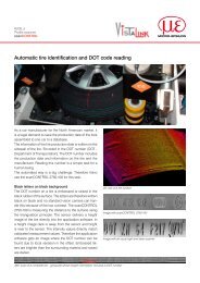
Funktionsprinzip, Technische Daten2.Funktionsprinzip, Technische Daten2.1MessprinzipDas Prinzip der kapazitiven Abstandsmessung mit dem System <strong>capaNCDT</strong> basiert auf der Wirkungsweisedes idealen Plattenkondensators. Bei leitenden Messobjekten bilden der Sensor und das gegenüberliegendeMessobjekt die beiden Plattenelektroden.Durchfließt ein konstanter Wechselstrom den Sensorkondensator, so ist die Amplitude der Wechselspannungam Sensor dem Abstand der Kondensatorelektroden direkt proportional. Die Wechselspannung wird gleichgerichtet,verstärkt und als Analogsignal ausgegeben.Das System <strong>capaNCDT</strong> wertet den Blindwiderstand X cdes Plattenkondensators aus, der sich streng proportionalmit dem Abstand ändert:1X c = ; Kapazität C = * *jCr oFlächeAbstandDieser theoretische Zusammenhang wird durch denAufbau der Sensoren als Schutzringkondensatoren in derPraxis nahezu ideal verwirklicht.Die lineare Charakteristik des Messsignals erreicht manbei Messungen gegen Messobjekte aus elektrisch leitendenWerkstoffen (Metallen) ohne eine zusätzliche elektronischeLinearisierung. Geringfügige Änderungen derLeitfähigkeit oder der magnetischen Eigenschaften wirkensich nicht auf die Empfindlichkeit oder Linearität aus.MasseSchirmelektrodeMesselektrodeElektrischer LeiterAbb. 1 Aufbau eines kapazitiven Sensors<strong>capaNCDT</strong> <strong>6100</strong>Seite 8
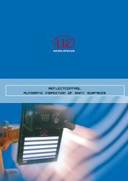
Funktionsprinzip, Technische Daten2.2 AufbauDas in einem Aluminiumgehäuse eingebaute berührungslose Einkanal-Messsystem des <strong>capaNCDT</strong> <strong>6100</strong>setzt sich zusammen aus:-- Controller-- Sensor und-- Sensorkabel.Im Controller befindet sich die Signalaufbereitungselektronik mit Oszillator, Demodulator und integriertemVorverstärker.Weiterhin sind auf der Signalverarbeitungsplatine die beiden Einstellpotentiometer „zero“ und „gain“. Mitihnen ist das Verstellen von Nullpunkt und Verstärkung möglich. Dadurch wird eine Feinabstimmung für dievorliegende Messaufgabe erreicht.Die Anschlussplatine enthält den 8-poligen Anschlussstecker, einen Verpolungsschutz und verschiedeneSchutzelemente der Anschlüsse, die zur Einhaltung der EMV-Richtlinien notwendig sind.Die Messwertanzeige ist nur extern möglich.Versorgungsspannung,AusgangssignalDeutschSynchronisation EinSensorSynchronisation AusAbb. 2 Messsystem <strong>capaNCDT</strong> <strong>6100</strong><strong>capaNCDT</strong> <strong>6100</strong>Seite 9
Funktionsprinzip, Technische Daten2.3 Technische DatenController-TypAuflösung statischAuflösung dynamischGrenzfrequenzGrenzfrequenz umschaltbarLinearitätMax. EmpfindlichkeitsabweichungLangzeitstabilitätSynchronbetrieb möglichIsolatormessungDT<strong>6100</strong>0,01 % d.M.0,015 % d.M. (2 kHz)2 kHz10 Hz / 2 kHz±0,3 % d.M. (alle Sensoren tauschbar ohne Kalibrierung)Option LC: ±0,1 % d.M. (abgestimmt auf einen Sensor)±0,1 % d.M.≤0,05 % d.M. / MonatjaneinTemperaturstabilität ±0,03 % d.M. / °CBetriebstemperaturController: +10 ... +60 °CSensor: -50 ... +150 °CLagertemperatur -10 … +75 °CVersorgungAusgangSensoren24 VDC / 85 mA (9 ... 36 VDC)optional ±15 VDC / 85 mA (9 ... 36 VDC)0 … 10 V (Lastwiderstand min. 1,2 kΩ / Lastkapazität max. 1 nF)optional: 4 … 20 mA (Bürde max. 400 Ω)alle Modelle außer CS005Elektromagnetische Verträglichkeit (EMV) DIN EN 61326-1: 2006-10 und DIN 61326-2-3: 2007-05d. M. = des Messbereiches<strong>capaNCDT</strong> <strong>6100</strong>Seite 10
Lieferung3.Lieferung3.1Lieferumfang1 Controller1 Sensor1 Sensorkabel mit Stecker1 Versorgungs- und Ausgangskabel PC3/8 (als Zubehör lieferbar)1 Gegenbuchse (wenn PC3/8 nicht mitbestellt wurde)1 BetriebsanleitungNehmen Sie die Teile des Messsystems vorsichtig aus der Verpackung und transportieren Sie sie soweiter, dass keine Beschädigungen auftreten können.Prüfen Sie die Lieferung nach dem Auspacken sofort auf Vollständigkeit und Transportschäden. BeiSchäden oder Unvollständigkeit wenden Sie sich bitte sofort an den Lieferanten.Deutsch3.2 LagerungLagertemperatur: -10 °C ... +75 °CLuftfeuchte: 5 bis 95 % RH (nicht kondensierend)<strong>capaNCDT</strong> <strong>6100</strong>Seite 11
Installation und Montage4.Installation und Montage4.1VorsichtsmaßnahmenAuf den Kabelmantel des Sensorkabels dürfen keine scharfkantigen oder schweren Gegenstände einwirken.Schützen Sie das Kabel in Bereichen mit erhöhtem Druck grundsätzlich vor Druckbelastung.Der minimale Biegeradius beträgt 10 mm. Vermeiden Sie auf jeden Fall Knicke.iÜberprüfen Sie die Steckverbindungen auf festen Sitz.Ein beschädigtes Kabel kann nicht repariert werden.4.2 SensorDie Sensoren des <strong>capaNCDT</strong> <strong>6100</strong> können freistehend oder bündig montiert werden.Achten Sie bei der Montage darauf, dass die polierte Sensorstirnfläche nicht zerkratzt wird.4.2.1 Radiale Punktklemmung mit MadenschraubeDiese einfache Befestigungsart ist nur bei kraft- und vibrationsfreiem Einbauort zu empfehlen. Die Madenschraubemuss aus Kunststoff sein, damit das Sensorgehäuse nicht beschädigt oder verformt werden kann.MadenschraubeAbb. 3 Radiale Punktklemmung mit MadenschraubeVerwenden Sie keine Metallmadenschrauben!>>Gefahr der Beschädigung des Sensors<strong>capaNCDT</strong> <strong>6100</strong>Seite 12
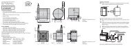
Installation und Montage4.2.2UmfangsklemmungDiese Art der Sensormontage bietet die höchste Zuverlässigkeit, da der Sensor über sein zylindrischesGehäuse flächig geklemmt wird. Sie ist bei schwierigen Einbauumgebungen, zum Beispiel an Maschinen,Produktionsanlagen und so weiter zwingend erforderlich.Montage mitSpannzangeAbb. 4 UmfangsklemmungDeutsch4.2.3Maßzeichnungen SensorenCS02CS05CS1HPCS16f78 1 12ø8f78 1 1215 120 -0 217 121 -0 2Steckerseiteø10f7ø10f7Abmessungen in mm, nicht maßstabsgetreu1) Montagebereich für Punkt- beziehungsweise Umfangsklemmung<strong>capaNCDT</strong> <strong>6100</strong>Seite 13
Installation und MontageCS2CS3CS5CS10M=1:2M=1:2M=1:2M=1:2ø20h7ø30h7ø40h7ø60h720 124 -0,216,5 124 -0,224 -0,216,5 116,5 124 -0,2ø20h7ø20h7ø20h7SteckerseiteCSE05912CSE1ø8f7ø7,7CSE2Ø14h7Ø13,7ø5,7ø6f791218,522SteckerseiteAbmessungen in mm, nicht maßstabsgetreu1) Montagebereich für Punkt- beziehungsweise Umfangsklemmung<strong>capaNCDT</strong> <strong>6100</strong>Seite 14
Installation und MontageCSH02, CSH05ø8g6ca. 9,4CSH1, CSH1,2ø12g6ca. 9,410 114ø7,533ca. 3710 114ø11,533ca. 37Deutschø2,2ø2,2Abmessungen in mm, nicht maßstabsgetreu<strong>capaNCDT</strong> <strong>6100</strong>Seite 15
Installation und MontageCSH2ø20g6Klemmbereichca. 9,4331014ø19.5ca. 37ø2,2Abmessungen in mm, nicht maßstabsgetreu<strong>capaNCDT</strong> <strong>6100</strong>Seite 16
Installation und MontageCSH02FL, CSH05FL40,1R4ca. 9,4CSH1FL, CSH1,2FL40,1R6ca. 9,43,54ø3M21,756,55,5ca. 37ø44,55ø3ø2,57,52,2511ca. 37Deutschø2,2ø2,2Abmessungen in mm, nicht maßstabsgetreu<strong>capaNCDT</strong> <strong>6100</strong>Seite 17
Installation und MontageCSH2FL51,6ø4ø2,22015,5ca. 9,40,17,615,520ca. 37ø3ø2,2Kabellänge 1,4 m sichtbar (incl. Crimphülse)Abmessungen in mm, nicht maßstabsgetreu<strong>capaNCDT</strong> <strong>6100</strong>Seite 18
Installation und Montage4.3 SensorkabelDer Sensor wird mit dem Controller über das mitgelieferte Sensorkabel verbunden. Der Anschluss erfolgt durch einfaches Stecken.Die Steckverbindung verriegelt selbstständig. Der feste Sitz kann durch Ziehen am Steckergehäuse (Kabelbuchse) geprüft werden.Durch Ziehen an der gerändelten Gehäusehülse der Kabelbuchse öffnet die Verriegelung und die Steckverbindung kann geöffnetwerden.Ø5,4Ø6Sensorkabel CCxC/90Sensorkabel CCxC 1613,717,58,6Ø3,2Kabellänge x2737Ø7Ø9,616,9813,1Ø6Ø5,4DeutschSensorkabel CCxBKabellänge xModell 2 gerade Stecker 1x gerader + 1x 90 ° für SensorenCCxC • 0,2 ... 0,5 mmCCxC/90 • 0,2 ... 0,5 mmCC2B • 1 ... 10 mmCC3B/90 • 1 ... 10 mm<strong>capaNCDT</strong> <strong>6100</strong>Ø3,22737Ø7Ø9,530,5Sensorkabel CCxB/902520,5Ø7Ø10x = 1 oder 3 mBiegeradius:Min. 10 mmiZugkraft amKabel ist unzulässig!Abmessungen inmm, nicht maßstabsgetreuSeite 19
Installation und Montage4.4Controller150 71 6454138Stromversorgung,Signalausgang64Befestigungsbohrungen fürSchrauben M4SENSORSYN AUS SYN EINBiegeradius PC3/8: 90 mm min.Abmessungen in mm, nicht maßstabsgetreu<strong>capaNCDT</strong> <strong>6100</strong>Seite 20
Installation und Montage4.5 Spannungsversorgung und Anzeige-/AusgabegerätSpannungsversorgung und Signalausgabe erfolgen über den 8-poligen Einbaustecker (DIN 45326). Pin-Belegung, siehe Abb. 5. Der Standard-Signalaufbereitungselektronik DT<strong>6100</strong> liegt eine 8-polige Kabelbuchsefür die anwenderseitige Konfektionierung eines eigenen Anschlusskabels bei.PIN1Belegung0 Volt (24 V-Betrieb)6 72 +15 Volt (Option)1833 Ausgang A Wegsignal/Spannung44 -15 V (Option)255 0 Volt (±15 V-Betrieb)6 +24 Volt (24 V-Betrieb) Lötstiftseite7 0 Volt (Analogausgang)Kabelbuchse8 Ausgang B Signal-Option (z.B. Strom)Abb. 5 Pin-BelegungiAnforderungen anVersorgungs- undAusgangskabelzur Erfüllung derEMV-Richtlinien.DeutschZusätzlich gilt:Verwenden Sie ein doppelt geschirmtes Kabel!-- Äußeres Schirmgeflecht umschließt alle Kabeladern.-- Inneres Schirmgeflecht umschließt Signalleitungen PIN 3, 7, 8-- Inneres Schirmgeflecht an PIN 7-- Gesamtschirm über Steckergehäuse an Gehäusemasse2--Empfohlener Leiterquerschnitt 0,14 mmDie EMV-Richtlinien, siehe Kap. 1.3, werden nur unter diesen Randbedingungen eingehalten.<strong>capaNCDT</strong> <strong>6100</strong>Seite 21
Installation und MontagePC3/8 ist ein 3 m langes, fertig konfektioniertes 8-adriges Versorgungs- und Ausgangskabel. Es wird alsZubehör geliefert.Anschlussbelegung und FarbcodesPIN Kabelfarbe Belegung1 weiß 0 Volt 24 VDC6 grün +24 Volt Versorgung2 braun +15 Volt ±15 VDC4 gelb -15 Volt Versorgung5 grau 0 Volt (Option)Äußerer KabelbereichmitGesamtschirm3 grün Ausgangssignal (Weg) / Spannung7 blau 0 Volt8 rot Ausgangssignal Optionenz.B. Strom 4 - 20 mAInneres Kabel,3-pol. mit SchirmungschwarzblankAußenschirmInnenschirm (mit Pin 7, blau, verbinden)<strong>capaNCDT</strong> <strong>6100</strong>Seite 22
Betrieb4.6Elektronik, Masseverbindung, ErdungDie Gehäuse der Sensoren sind über Kondensatoren mit der Signalmasse und der Versorgungsmasse verbunden.Bei der 24 V-Versorgung sind Versorgungs- und Signalmasse galvanisch getrennt.Mit der Sensormontage in eine metallische Halterung ist eine ausreichende Masseverbindung hergestellt.Bei kleinen, isoliert aufgebauten Messobjekten ist eine zusätzliche Masseverbindung notwendig. Dazu mussdas Messobjekt mit dem Sensorgehäuse verbunden werden.5.5.1iBetriebInbetriebnameSchließen Sie die Anzeige-/Ausgabegeräte über die Signalausgangsbuchse an, bevor Sie das Gerät andie Stromversorgung anschließen und diese einschalten, siehe Kap. 4.5.Lassen Sie das Messsystem nach Anlegen der Spannungsversorgung ca. 1 Minute warmlaufen.Deutsch5.2GrundeinstellungenMit den Trimmpotentiometern „gain“ und „zero“, siehe Abb. 6, werden Verstärkungs- und Nullpunktabgleichdes Messkanals durchgeführt (Einstellbereich ca. 10 Umdrehungen je Potentiometer).Die Endstellungen bei linkem bzw. rechtem Anschlag sind durch leichtes Klicken zu erkennen.<strong>capaNCDT</strong> <strong>6100</strong>Seite 23
BetriebGainSensor/SynchronisationVersorgung/AusgangAbb. 6 Signalverarbeitungsplatine mit EinstellungselementeniZeroUnterbrechen Sie die Spannungsversorgung vor Berührung der Sensoroberfläche.>>statische Entladung>>VerletzungsgefahrBei einem normierten Einstellwert gilt folgende Zuordnung:Trimm-Position Einstellung normierter WertLinker Anschlag minimal 0.00Mitte mittel 5.00Rechter Anschlag maximal 10.00<strong>capaNCDT</strong> <strong>6100</strong>Seite 24
Betrieb5.3 Kalibrierung mit metallischen MessobjektenVoraussetzung - spez. Widerstand des Messobjekts < 1000 Ωcm.Einstellung von Nullpunkt und Verstärkung:Die Elektronik wird gemäß der Anschlussbelegung mit der Spannungsversorgung und dem Anzeigegerätverbunden.Aufgrund von Messprinzip und Sensorkonstruktion ist bei metallischen Messobjekten automatisch eine lineareCharakteristik gegeben.Das Messgerät ist werkseitig so eingestellt, dass für den Sensor CS2 entsprechend seinem Messbereich eineEmpfindlichkeit von 10 V erreicht wird.Bei Sensoren mit anderen Messbereichen wird eine Nachkalibrierung wie folgt durchgeführt:Schritt 1Schritt 2Öffnen Sie den Deckel des Controllers.Stellen Sie den Abstand zwischen Sensoroberfläche und Messobjekt (möglichst gleiche Materialeigenschaftenwie beim Betrieb) auf Messbereichsanfang ein.Stellen Sie die Ausgangsspannung mit Trimm-Potentiometer „zero“ auf 0 V ein.Bestimmen Sie gewünschten maximalen Abstand (Messbereichsende) zwischen Sensoroberfläche undMessobjekt.Stellen Sie die Ausgangsspannung mit Mit Trimm-Potentiometer „gain“ auf 10 V ein.Deutsch<strong>capaNCDT</strong> <strong>6100</strong>Seite 25
BetriebSchritt 3Wiederholen Sie Schritte 1 und 2 ca. drei Mal, bis sich eine stabile Trimmpotentiometereinstellung ergibt.Schließen Sie den Gehäusedeckel.10 V20 V10 % Messbereich 100 %Abb. 7SensorBei schräg stehendem Sensor bzw. Messobjekt tritt entsprechend der Verkippung eine Messbereichsreduzierungund eine Nullpunktverschiebung auf.Gewölbte Messobjektoberflächen führen bei kleineren Abständen zwischen Sensor und Messobjekt zu Linearitätseinbußen.Bei kleiner Messobjektoberfläche treten ebenfalls Linearitäts- und Empfindlichkeitsabweichungen auf.AusgangsspannungMessobjektVerlauf der Ausgangsspannung im Messbereich1 = Messbereichsanfang2 = MessbereichsendeBei Controllern mit Option I (Stromausgang) werden in Analogie die Werte-- 4 mA (Messbereichsanfang) und-- 20 mA (Messbereichsende) eingestellt.<strong>capaNCDT</strong> <strong>6100</strong>Seite 26
Betrieb5.4SystemgrenzfrequenzBei langsamen, dynamischen Messungenist es vorteilhaft, die Grenzfrequenzdes Systems auf 10 Hz zu reduzieren.Damit wird eine Verringerung des Rauschensund eine Erhöhung der Auflösungerreicht.Systemgrenzfrequenz auf 10 Hz einstellen:Schieben Sie bei geöffnetem Controllerden Schalter S1 nach links,siehe Abb. 8.Versorgung/AusgangSchalterstellung S12 kHz (Auslieferungszustand)10 HzDeutschAbb. 8 Systemgrenzfrequenz<strong>capaNCDT</strong> <strong>6100</strong>Seite 27
Betrieb5.5Synchronisation bei MehrkanalsystemMehrere Messsysteme der Serie <strong>capaNCDT</strong> <strong>6100</strong> können gleichzeitig als Mehrkanalsystem betrieben werden.Durch die Synchronisation der Messsysteme wird ein gegenseitiges Beeinflussen der Sensoren vermieden:Stecken Sie das Synchronisationskabel SC30 (Zubehör) in die Buchse SYN OUT (Synchronisations Ausgang)an Controller 1.Stecken Sie den zweiten Stecker am Kabel in die Buchse SYN IN (Synchronisation Eingang) an Controller2.-- Der Oszillator von Controller 2 schaltet automatisch auf Synchronisationsbetrieb, d.h. in Abhängigkeit vomOszillator von Controller 1-- der Einfluss bei schlecht geerdetem Messobjekt wird ausgeschlossen.Synchronisieren Sie ggf. mehrere Messsysteme mit Kabel SC30.Controller 1 Controller 2 Controller 3SYNOUTSYNINSC30SYNOUTSYNINSC30Abb. 9 Synchronisation mehrerer MesssystemeiAutomatische Synchronisation, jeder Controller kann Master sein.Biegerradius SC30:-- 30 mm (fest)-- 60 mm (bewegt)<strong>capaNCDT</strong> <strong>6100</strong>Seite 28
Betrieb und Wartung6.Betrieb und WartungAchten Sie darauf, dass stets eine saubere Sensoroberfläche vorhanden ist.Schalten Sie vor der Reinigung die Versorgungsspannung ab.Reinigen Sie mit einem feuchten Tuch.Reiben Sie anschließend die Sensoroberfläche trocken.Unterbrechen Sie vor Berührung der Sensoroberfläche die Spannungsversorgung.>>statische Entladung>>VerletzungsgefahrBei Änderung des Messobjekts oder bei sehr langen Betriebszeiträumen (Langzeitfehler) kann es zu leichtenEinbußen der Betriebsqualität kommen. Diese können durch ein Nachkalibrieren, siehe Kap. 5.3, beseitigtwerden.Bei einem Defekt des Controllers, des Sensors oderdes Sensorkabels senden Sie bitte die betreffendenTeile zur Reparatur oder zum Austausch ein. BeiStörungen, deren Ursachen nicht eindeutig erkennbarsind, senden Sie bitte immer das gesamteMesssystem anMICRO-EPSILON MESSTECHNIKGmbH & Co. KGKönigbacher Str. 15D-94496 OrtenburgTelefon: +49/8542/168 - 0Fax: +49/8542/168 - 90info@micro-epsilon.dewww.micro-epsilon.deDeutsch<strong>capaNCDT</strong> <strong>6100</strong>Seite 29
Haftung für Sachmängel7.Haftung für SachmängelAlle Komponenten des Gerätes wurden im Werk auf die Funktionsfähigkeit hin überprüft und getestet.Sollten jedoch trotz sorgfältiger Qualitätskontrolle Fehler auftreten, so sind diese umgehend an MICRO-EPSI-LON oder den Händler zu melden.Die Haftung für Sachmängel beträgt 12 Monate ab Lieferung. Innerhalb dieser Zeit werden fehlerhafte Teile,ausgenommen Verschleißteile, kostenlos instand gesetzt oder ausgetauscht, wenn das Gerät kostenfrei anMICRO-EPSILON eingeschickt wird.Nicht unter die Haftung für Sachmängel fallen solche Schäden, die durch unsachgemäße Behandlung oderGewalteinwirkung entstanden oder auf Reparaturen oder Veränderungen durch Dritte zurückzuführen sind.Für Reparaturen ist ausschließlich MICRO-EPSILON zuständig.Weitergehende Ansprüche können nicht geltend gemacht werden. Die Ansprüche aus dem Kaufvertrag bleibenhierdurch unberührt.MICRO-EPSILON haftet insbesondere nicht für etwaige Folgeschäden.Die Ansprüche aus dem Kaufvertrag belieben hierdurch unberührt.Im Interesse der Weiterentwicklung behalten wir uns das Recht auf Konstruktionsänderungen vor.8.Außerbetriebnahme, EntsorgungEntfernen Sie die elektrische Anschlussleitung für die Versorgungsspannung und Ausgangssignal amController.Entfernen Sie die elektrischen Anschlussleitungen zwischen Sensor und Controller.Das <strong>capaNCDT</strong> <strong>6100</strong> ist entsprechend der Richtlinie 2002/95/EG, „RoHS“, gefertigt.Führen Sie die Entsorgung entsprechend den gesetzlichen Bestimmungen durch (siehe Richtlinie2002/96/EG).<strong>capaNCDT</strong> <strong>6100</strong>Seite 30
Anhang9.MC2,5MC25DPS2020AnhangMikrometer-Kalibiervorrichtung, Einstellbereich 0 - 2,5 mm, Ablesung 0,1 µm, für Sensoren CS05bis CS1Digitale Mikrometer-Kalibriervorrichtung, Einstellbereich 0 - 25 mm, verstellbarer Nullpunkt, füralle SensorenNetzgerät 24 V / 2,5 A; Eingang 100 - 240 VAC, Ausgang 24 VDC / 2,5 A; Montage auf symmetrischerNormschiene 35 mm x 7,5 mm, DIN 50022; für max. 4 Multifunktions-Controller DT 3301FC8 8-polige Kabelbuchse DIN 45326PC3/8 8-adriges Anschlusskabel mit Kabelbuchse DIN 45326SC30CSP 301Synchronisationskabel, 30 cm langDigitaler Signalprozessor mit Display zur synchronen Verarbeitung von 2 MesskanälenSensoren, Sensorkabel, siehe Kap. 4.2, siehe Kap. 4.3SWH VakuumdurchführungDeutschM10x0,7534213,8914SW12max. 17<strong>capaNCDT</strong> <strong>6100</strong>Seite 31
Contents1. Safety......................................................................................................................................... 351.1 Symbols Used.................................................................................................................................................. 351.2 Warnings........................................................................................................................................................... 351.3 Notes on CE Identification................................................................................................................................ 361.4 Proper Use........................................................................................................................................................ 361.5 Proper Environment.......................................................................................................................................... 372. Functional Principle, Technical Data........................................................................................ 382.1 Measuring Principle.......................................................................................................................................... 382.2 Structure........................................................................................................................................................... 392.3 Technical Data.................................................................................................................................................. 403. Delivery...................................................................................................................................... 413.1 Unpacking........................................................................................................................................................ 413.2 Storage............................................................................................................................................................. 414. Installation and Assembly........................................................................................................ 424.1 Precautionary Measures................................................................................................................................... 424.2 Sensor............................................................................................................................................................... 424.2.1 Sensor Radial Point Clamping with Grub Screw............................................................................................. 424.2.2 Circumferential Clamping................................................................................................................................. 434.2.3 Dimensional Drawings Sensors....................................................................................................................... 434.3 Sensor Cable ................................................................................................................................................... 494.4 Controller.......................................................................................................................................................... 504.5 Power Supply and Signal Output..................................................................................................................... 514.6 Electronics, Ground Connection, Earthing...................................................................................................... 535. Operation................................................................................................................................... 535.1 Starting Up........................................................................................................................................................ 535.2 Basic Settings................................................................................................................................................... 535.3 Calibration with Metal Targets.......................................................................................................................... 555.4 Frequence Response....................................................................................................................................... 575.5 Synchronization in Multichannel Systems....................................................................................................... 58<strong>capaNCDT</strong> <strong>6100</strong>English
6. Maintenance.............................................................................................................................. 597. Warranty.................................................................................................................................... 608. Decommissioning, Disposal..................................................................................................... 609. Appendix................................................................................................................................... 61<strong>capaNCDT</strong> <strong>6100</strong>
Safety1.SafetyThe handling of the sensor assumes knowledge of the instruction manual.1.1Symbols UsedThe following symbols are used in this instruction manual:Indicates a hazardous situation which, if not avoided, may result in minor or moderateinjury.Indicates a situation which, if not avoided, may lead to property damage.i1.2WarningsIndicates a user action.Indicates a user tip.Disconnect the power supply before touching the sensor surface.>>Static discharge>>Danger of injuryEnglishConnect the power supply and the display/output device in accordance with the safety regulations for electricalequipment.>>Danger of injury>>Damage to or destruction of the sensor and/or controllerAvoid banging and knocking the sensor and controller>>Damage to or destruction of the sensor and/or controllerThe power supply may not exceed the specified limits.>>Damage to or destruction of the sensor and/or controller<strong>capaNCDT</strong> <strong>6100</strong>Protect the sensor cable against damage>>Destruction of the sensor> >Failure of the measuring devicePage 35
Safety1.3 Notes on CE IdentificationThe following applies to the <strong>capaNCDT</strong> <strong>6100</strong>: EMC regulation 2004/108/ECProducts which carry the CE mark satisfy the requirements of the EMC regulation 2004/108/EC ‘ElectromagneticCompatibility’ and the European standards (EN) listed therein. The EC declaration of conformity is keptavailable according to EC regulation, article 10 by the authorities responsible atMICRO-EPSILON MESSTECHNIKGmbH & Co. KGKönigbacher Straße 1594496 OrtenburgThe system is designed for use in industry and satisfies the requirements of the standards:-- DIN EN 61326-1: 2006-10-- DIN 61326-2-3: 2007-05The system fulfills the specification of the EMC requirements, if the instructions in the operating manual arefollowed.1.4 Proper Use-- The <strong>capaNCDT</strong> <strong>6100</strong> measuring system is designed for use in industrial areas. It is used for• displacement, distance and movement measurement.• position measuring of parts or machine components.--The system may only be operated within the limits specified in the technical data, see Chap. 2.3.-- Use the system only in such a way that in case of malfunction or failure personnel or machinery are notendangered.-- Take additional precautions for safety and damage prevention for safety-related applications.<strong>capaNCDT</strong> <strong>6100</strong>Page 36
Safety1.5 Proper Environment-- Operating temperature:• Sensor and cable: -50 ... +150 °C (-58 to +302 °F)• Controller: +10 ... +60 °C (+50 to +140 °F)-- Storage temperature: -10 °C ... +75 °C (+14 to 167 °F)-- Humidity:5 - 95 % (non condensing)-- Ambient pressure: Atmospheric pressure-- EMC: Acc. to DIN EN 61326-1: 2006-10DIN 61326-2-3: 2007-05-- The space between the sensor surface and the target must have an un-varying dielectric constant andmay not be contaminated (e.g. water, rubbed-off parts, dust, etc.).English<strong>capaNCDT</strong> <strong>6100</strong>Page 37
Functional Principle, Technical Data2.2.1Functional Principle, Technical DataMeasuring PrincipleThe principle of capacitive distance measurement with the <strong>capaNCDT</strong> system is based on the principle of theparallel plate capacitor. For conductive targets, the sensor and the target opposite form the two plate electrodes.If a constant AC current flows through the sensor capacitor, the amplitude of the AC voltage at the sensor isproportional to the distance between the capacitor electrodes. The AC voltage is demodulated, amplified andoutput as an analog signal.The <strong>capaNCDT</strong> system evaluates the reactance X cof the plate capacitor which changes strictly in proportionto the distance.1areaX c = ; capacitance C = * *jCr o distanceThis theoretical relationship is realized almost ideallyin practice by designing the sensors as guard ringcapacitors.The linear characteristic of the measuring signal isachieved for electrically conductive target materials(metals) without any additional electronic linearization.Slight changes in the conductivity or magnetic propertiesdo not affect the sensitivity or linearity.GroundScreening electrodeMeasuring electrodeElectrical conductorFig. 1 Functional principle of the guard ringcapacitor<strong>capaNCDT</strong> <strong>6100</strong>Page 38
Functional Principle, Technical Data2.2StructureThe non-contact, single-channel measuring system of the <strong>capaNCDT</strong> <strong>6100</strong> installed in an aluminium housing,consists of:-- Controller-- Sensor and-- sensor cable.The controller consists a connecting board and a signal conditioning board which are both enclosed in themetal housing.The board also contains the „zero“ and the „gain“ potentiometers which are used for adjusting the zero pointand the gain. This allows optimization of the current measuring task.The connecting board contains the 8-pin connector, reverse polarity protection and various protection elementsfor the connections which are necessary to satisfy the EMC regulations.The output signal can only be displayed externally.Power supply,output signalEnglishSynchronization inputSensorSynchronization outputFig. 2 Measuring system <strong>capaNCDT</strong> <strong>6100</strong><strong>capaNCDT</strong> <strong>6100</strong>Page 39
Functional Principle, Technical Data2.3 Technical DataController typeResolution staticResolution dynamicLimit frequencyLimit frequency adjustableLinearityMax. sensitivity deviationLong term stabilitySynchronous operationInsulator measurementDT<strong>6100</strong>0.01 % FSO0.015 % d.M. (2 kHz)2 kHz10 Hz / 2 kHz±0.3 % d.M. (all sensors interchangeable without calibration)Option LC: ±0.1 % FSO (tuned to one sensor)±0.1 % FSO≤ 0.05 % FSO / MonthTemperature stability ±0.03 % FSO / °COperating temperatureStorage temperatureSupplyOutputSensorsyesnoController: +10 ... +60 °C (+50 to +140 °F)Sensor: -50 ... +150 °C (-58 to +302 °F)-10 … +75 °C (+14 ... +167 °F)24 VDC / 85 mA (9 ... 36 VDC)optional ±15 VDC / 85 mA (9 ... 36 VDC)0 … 10 V (resistance min. 1.2 kΩ / capacitance max. 1 nF)optional: 4 … 20 mA (load max. 400 Ω)all sensors außer CS005Electromagnetic compatibility (EMC) DIN EN 61326-1: 2006-10 and DIN 61326-2-3: 2007-05FSO = Full Scale Output<strong>capaNCDT</strong> <strong>6100</strong>Page 40
Delivery3.Delivery3.1Unpacking1 Controller1 Sensor1 Sensor cable with plug1 Power and output cable PC3/8 (available as an accessory)1 Plug (if PC3/8 was not ordered)1 Instruction manualRemove the parts of the system carefully from the packaging and transport them in such a way that theyare not damaged.Check for completeness and shipping damages immediately after unpacking. In case of damage ormissing parts, please contact the manufacturer or supplier.3.2 StorageStorage temperature:Humidity:-10 °C ... +75 °C (+14 to +167 °F)5 - 95 % (non condensing)English<strong>capaNCDT</strong> <strong>6100</strong>Page 41
Installation and Assembly4.Installation and Assembly4.1Precautionary MeasuresNo sharp-edged or heavy objects may come into contact with the sensor cable sheath.Protect the cable in pressurised rooms against pressure loads.The minimum bending radius is 10 mm (.39 inch). Avoid kinks at all cost.iCheck the connections for tight fit.A damaged cable cannot be repaired.4.2 SensorThe sensors of the <strong>capaNCDT</strong> <strong>6100</strong> may be mounted free-standing or flush.When assembling, make sure that the polished sensor surface is not scratched.4.2.1 Sensor Radial Point Clamping with Grub ScrewThis simple type of fixture is only recommended for a force and vibration-free installation position. The grubscrew must be made of plastic so that it cannot damage or deform the sensor housing.Grub screwFig. 3 Radial point clamping with grub screwDo not use metal grub screws!>>Danger of damaging the sensor<strong>capaNCDT</strong> <strong>6100</strong>Page 42
Installation and Assembly4.2.2Circumferential ClampingThis sensor mounting option offers maximum reliability because the sensor is clamped around its cylindricalhousing. It is absolutely necessary in difficult installation environments, e.g. on machines, production plantsetc.Mounting withclamping ringFig. 4 Circumferential clamping4.2.3Dimensional Drawings SensorsCS02CS05CS1HPCS18 1 (.315)ø6f7 (.236 dia.)12(.472)8 1 (.315)12(.472)ø8f7 (.314 dia.)15 1 (.590)20 -0,2(.787 -008 )21 -0,2(.826 -008 )17 1 (.669)EnglishConnector sideDimensions in mm (inches), not to scaleø10f7 (.394 dia.)ø10f7 (.394 dia.)1) Adjustment area for radial point respectively circumferential clamping<strong>capaNCDT</strong> <strong>6100</strong>Page 43
Installation and AssemblyCS2CS3CS5CS10M=1:2ø20h7 (.79 dia.)20 1 (.787)24 -0.2(.945) -0.08M=1:2ø30h7 (1.18 dia.)16.5 1 ( .649)24 -0,2(.945) -0.08M=1:2ø40h7 (1.58 dia.)16.5 1 ( .649)24 -0,2(.945) -0.08M=1:2ø60h7 (2.36 dia.)16.5 124 -0,2ø20h7 (.79 dia.)ø20h7 (.79 dia.)ø20h7 (.79 dia.)Connector sideCSE059 (.35)12 (.47)ø5.7 (.22)ø6f7(.24 dia.)CSE1ø8f7 (0.31 dia.)ø7.7 (0.30 dia.)9 (0.35)12 (0.47)CSE2ø14h7 (0.55 dia.)ø13.7 (0.54 dia.)18.5 (0.73)22 (0.87)Connector sideDimensions in mm (inches), not to scale1) Adjustment area for radial point respectively circumferential clamping<strong>capaNCDT</strong> <strong>6100</strong>Page 44
Installation and AssemblyCSH02, CSH05ø8g6 (.315 dia.)ca. 9.4 (.37)CSH1, CSH1.2ø12g6 (.473 dia.)ca. 9.4 (.37)10 1 (.39)14(.39)ø7.5(.30 dia.)33(1.30)Englishca. 37 (1.46)10 1 (.39)14(.39)ø11.5(.45 dia.)33(1.30)ca. 37 (1.46)ø2.2 (.09 dia.)ø2.2 (.09 dia.)Dimensions in mm (inches), not to scale<strong>capaNCDT</strong> <strong>6100</strong>Page 45
Installation and Assembly33 (1.3)CSH2ø20g6(0.79 g6 dia.)ca. 9.4 (.37)Clamparea10(.39)14(.55)ø19.5(.77 dia.)ca. 37 (appr. 1.46)ø2.2(.09 dia)Dimensions in mm (inches), not to scale<strong>capaNCDT</strong> <strong>6100</strong>Page 46
Installation and AssemblyCSH02FL, CSH05FL4 (.16)0.1 (.003)3.5(.14)4(.16)ø3(.12 dia.)M2R4 (.16)1.75(.07)5.5(.22)6.5(.25)ca. 9.4 (.37)ca. 37 (1.46)ø4(.16 dia.)CSH1FL, CSH1.2FL4 (.16)0.1(.003)4.5(.18)5(.20)ø2.5(.10)ø3(.12 dia.)R6(.24)2.25(.09)7.5(.29)11 (.43)ca. 9.4 (.37)ca. 37 (1.46)ø2.2(.09 dia.)ø2.2(.09 dia.)EnglishDimensions in mm (inches), not to scale<strong>capaNCDT</strong> <strong>6100</strong>Page 47
Installation and Assembly1.6( 06)CSH2FL5( 20)ø2.2( 09 dia )20 (.79)15.5 (.61)ca. 9.4(appr. .37)ø4(.16 dia )0.1( 003)7.6(.30)ø3(.12 dia )15.5 ( 61)20 (.79)ca. 37 (appr. 1.46)ø2.2( 09 dia )Cable length 1.4 m visible (incl. crimp sleeve)Dimensions in mm (inches), not to scale<strong>capaNCDT</strong> <strong>6100</strong>Page 48
Installation and Assembly4.3 Sensor CableThe sensor is connected to the signal conditioning electronics by the sensor cable. The connection is made by simple plugging.The connector locks automatically. The tight fit can be checked by pulling the connector housing (cable bushing). The lock can bereleased and the connector can be opened by pulling the knurled housing sleeve of the cable bushing.Ø5.4 (.21 dia.)Ø6 (.24 dia.)8.6 (.34)13.7 (.54)17.5 (.69)Sensor cable CCxCØ3.2(.13 dia)Cable length x27 (1.06)37 (1.46)Ø7 (.28 dia.)Ø9.6 (.38 dia.)x = 1 or 3 mBending radius:10 mm miniTension at the cableis inadmissible!Dimensions in mm(inches), not to scale16.9 (.67)Sensor cable CCxC/9016 (10.08)8 (.31)13.1(.52)Ø6(.24 dia)Ø5.4(.21 dia.)Sensor cable CCxB/90Sensor cable CCxB 25 (.98)Ø3.2(.13 dia.)Cable length x27 (1.06)37 (1.46)Ø7 (.28 dia.)Ø9.5 (.37 dia.)20.5 (.81)30.5 (1.20)EnglishModel 2 straight connectors 1x straight + 1 angled connector 90 ° for sensorsCCxC • 0.2 ... 0.5 mmCCxC/90 • 0.2 ... 0.5 mmCC2B • 1 ... 10 mmCC3B/90 • 1 ... 10 mm<strong>capaNCDT</strong> <strong>6100</strong>Ø7 (.28 dia.)Ø10 (.39 dia.)Page 49
Installation and Assembly4.4Controller150 (5.91) 71 (2.80) 64 (2.52)54 (2.16)Power supply,Signal output138 (5.43)64 (2.52)Mounting holes for M4 or3/16“ screwsSENSORSYN OUTSYN INBending radius PC3/8: 90 mm min.Dimensions in mm (inches), not to scale<strong>capaNCDT</strong> <strong>6100</strong>Page 50
Installation and Assembly4.5 Power Supply and Signal OutputThe power supply and signal output are connected by the 8-pin built-in connector (DlN 45326). Pin assignment,see Fig. 5. The controller contains a 8-pin cable socket for the user-side assembly of your own connectingcable.PIN1Assignment0 Volt (24 V operation)6 72 +15 Volt (Option)1833 Output A displacement signal/voltage44 -15 V (Option)255 0 Volt (±15 V operation)6 +24 Volt (24 V operation) Solder pin side7 0 Volt (analog output)cable socket8 Output B signal option (e.g. current)Fig. 5 Pin assignmentIn addition the following applies:Use a double screened cable!-- Outer screening mesh surrounds all cable wires.-- Inner screening mesh surrounds signal wires PIN 3, 7, 8.-- Inner screening mesh at pin 7.-- Total screen via connector housing to housing ground2--Recommended conductor cross-section 0.14 mm (AWG 26)The EMC regulations, see Chap. 1.3, are only satisfied under these basic conditions.iRequirements ofpowerand outputcables to satisfythe EMC regulations.English<strong>capaNCDT</strong> <strong>6100</strong>Page 51
Installation and AssemblyPC3/8 is a 3 m (9.84 ft) long, pre-assembled 8-wire power and output cable. It is supplied as an accessory.Pin assignment and color codesPIN Cable color Assignment1 white 0 Volt 24 VDC6 green +24 Volt Power2 brown +15 Volt ±15 VDC4 yellow -15 Volt Power5 grey 0 Volt (Option)Outer cablearea with totalscreen3 green Output signal (distance) / voltage7 blue 0 Volt8 red Output signal optionse.g. current 4 - 20 mAInner cable,3-wire with screenblackbareOuter screenInner screen (connect with Pin 7, blue)<strong>capaNCDT</strong> <strong>6100</strong>Page 52
Operation4.6Electronics, Ground Connection, EarthingThe sensor housings are connected to signal ground and to supply ground by capacitors.Signal ground and supply ground are dc-insulated for the 24 V option.Mounting the sensor in a metal holder establishes a sufficient ground connection.An additional groundconnection is required for small, remotely located targets. Connect the target to thesensor housing for this.5.Operation5.1i5.2Starting UpConnect the display/output devices through the signal output socket, see Chap. 4.5, before connectingthe device to the power supply and switching on the power supply.Allow the measuring system to warm up for about one minute before the first measurement or calibration.Basic SettingsThe gain and zero point of the measuring channel are adjusted with the ’gain’ and ’zero’ trimmer potentiometers,see Fig. 6, (setting range approx. 20 turns per potentiometer).The end settings at the left and right stops are recogniceable by a slight click.English<strong>capaNCDT</strong> <strong>6100</strong>Page 53
OperationGainSensor/SynchronizationPower/OutputFig. 6 Signal conditioning board with trimmer potentiometersiZeroDisconnect the power supply before touching the sensor surface.>>Static discharge>>Danger of injuryThe following assignment applies for a standardized setting value:Trimmer position Adjustment Standardized valueLeft stop Minimum 0.00Middle Medium 5.00Right stop Maximum 10.00<strong>capaNCDT</strong> <strong>6100</strong>Page 54
Operation5.3 Calibration with Metal TargetsPrecondition - spec. resistance of the target < 1000 Ωcm.Adjustment of the zero point and gain:The controller is connected to the power supply and the display device according to the connection assignment.A linear characteristic is produced automatically due to the measuring principle and sensor construction.The measuring device is set at the factory to 10 Volt FSO valid for sensor CS2 according to its measuringrange.Sensors with other measuring ranges are recalibrated as follows:Step 1Step 2Open the cover of the controller.Set the distance between the sensor surface and the target (use identical material for calibration andoperation) to start of measuring range.Set the output voltage to 0 V with the ’zero’ potentiometer.Determine the desired maximum distance (end of measuring range) between the sensor surface and thetarget.Set the output voltage to 10 V with the ’gain’ potentiometer.English<strong>capaNCDT</strong> <strong>6100</strong>Page 55
OperationStep 3Repeat steps 1 and 2 about three times until a stable potentiometer setting results.Replace the housing cover.If the sensor face and the target are mismatched (not parallel), there will be a loss in the range and a shift inthe zero point depending on the tilt.Curved target surfaces cause linearity reductions if the distance between the sensor and the target is small.Linearity and sensitivity deviations also occur with a too small target dimensions.10 V2Outputvoltage0 V10 % Measuring range 100 %SensorFig. 7 Calibration stepsTarget1 = Start of measuring range2 = End of measuring rangeController with option I (current output):The values-- 4 mA (start of measuring range) and-- 20 mA (end of measuring range) are set for systems with current output.<strong>capaNCDT</strong> <strong>6100</strong>Page 56
Operation5.4Frequence ResponseFor slow dynamic measurements it isprofitable to reduce the cut-off frequencyto 10 Hz. Effect:-- Noise decreases.-- Resolution increases.Set the cut-off frequency to 10 Hz:Open the controller.Shift the switch S1 in the left position,see Fig. 8.Power/outputSwitch S12 kHz (Factory setting)10 HzFig. 8 Frequence ResponseEnglish<strong>capaNCDT</strong> <strong>6100</strong>Page 57
Operation5.5Synchronization in Multichannel SystemsSeveral measuring systems in the <strong>capaNCDT</strong> <strong>6100</strong> series can be operated simultaneously as multichannelsystems.Synchronization of the measuring systems avoids interference between the sensors:Plug SC30 synchronization cable (accessory) in the SYN OUT (synchronization output) socket in controller1.Plug the other end on the cable into the SYN IN (synchronization input) in controller 2.-- The oscillator of controller 2 switches automatically to synchronization mode, i.e. it acts as slave to themaster oscillator in controller 1.-- The influence of unsufficient grounded targets will be excepted.Synchronise several measuring systems with SC30 cable if necessary.Controller 1 Controller 2 Controller 3SYNOUTSYNINSC30SYNOUTSYNINSC30Fig. 9 Synchronization in multichannel systemsiAutomatic synchronization, each controller can work as master.Bending radius SC30:-- 30 mm (one time)-- 60 mm (alternating)<strong>capaNCDT</strong> <strong>6100</strong>Page 58
Maintenance6.MaintenanceMake sure that the sensor surface is always clean.Switch off the power supply before cleaning.Clean with a clamp cloth; then rub the sensor surface dry.Disconnect the power supply before touching the sensor surface.>>Static discharge>>Danger of injuryChanging the target or very long operating times can lead to slight reductions in the operating quality (longtermerrors). These can be eliminated by recalibration, see Chap. 5.3.In the event of a defect on the controller, the sensoror the sensor cable please send us the effectedparts for repair or exchange. In the case of faultsthe cause of which is not clearly identifiable, sendthe whole measuring system back toMICRO-EPSILON MESSTECHNIKGmbH & Co. KGKönigbacher Str. 15D-94496 Ortenburg / GermanyTelefon: +49/8542/168 - 0Fax: +49/8542/168 - 90info@micro-epsilon.dewww.micro-epsilon.comEnglish<strong>capaNCDT</strong> <strong>6100</strong>Page 59
Warranty7.WarrantyAll components of the device have been checked and tested for perfect function in the factory. In the unlikelyevent that errors should occur despite our thorough quality control, this should be reported immediately to<strong>Micro</strong>-<strong>Epsilon</strong>.The warranty period lasts 12 months following the day of shipment. Defective parts, except wear parts, will berepaired or replaced free of charge within this period if you return the device free of cost to <strong>Micro</strong>-<strong>Epsilon</strong>.This warranty does not apply to damage resulting from abuse of the equipment and devices, from forcefulhandling or installation of the devices or from repair or modifications performed by third parties.No other claims, except as warranted are accepted.<strong>Micro</strong>-<strong>Epsilon</strong> will specifically not be responsible for eventual consequential damage. The terms of thepurchasing contract apply in full.<strong>Micro</strong>-<strong>Epsilon</strong> always strives to supply the customers with the finest and most advanced equipment.Development and refinement is therefore performed continuously and the right to design changes withoutprior notice is accordingly reserved.For translations in other languages, the data and statements in the German language operation manual areto be taken as authoritative.8.Decommissioning, DisposalDisconnect the cable for electrical power and output signal on the controller.Disconnect the cable between sensor and controller.The <strong>capaNCDT</strong> <strong>6100</strong> is produced according to the directive 2002/95/EC („RoHS“).Do the disposal according to the legal regulations (see directive 2002/96/EC).<strong>capaNCDT</strong> <strong>6100</strong>Page 60
Appendix9.MC2.5MC25DPS2020Appendix<strong>Micro</strong>meter calibration fixture, range 0 - 2.5 mm, division 0.1 µm, for sensors CS05 to CS1Digital micrometer calibration fixture, range 0 - 25 mm, adjustable offset, for all sensorsPower supply 24 V / 2.5 A; input 100 - 240 VAC, output 24 VDC / 2.5 A; Mounting on symmetricalDIN rail 35 mm x 7.5 mm, DIN 50022; for max. 4 multifunction controller DT 3301FC8 8-pin cable socket DIN 45326PC3/8SC30CSP 301Power- and output cable, 3 m (9.84 ft) long, 8-wireSynchroniztion cable, 30 cm longDigital signal processing unit with display for synchronous processing of 2 channelsSensors, sensor cable, see Chap. 4.2, see Chap. 4.3SWHVacuum feed through13.8 (.54)M10x0.75WS1234 (1.34)max. 17(.67)2 (0.08)9(.35)14(.55)English<strong>capaNCDT</strong> <strong>6100</strong>Page 61
MICRO-EPSILON MESSTECHNIK GmbH & Co. KGKönigbacher Str. 15 · 94496 Ortenburg / GermanyTel. +49 (0) 8542 / 168-0 · Fax +49 (0) 8542 / 168-90info@micro-epsilon.de · www.micro-epsilon.comX975X111-B061092HDRMICRO-EPSILON MESSTECHNIK*X975X111-B06*