Assembly instructions draw wire sensor take up ... - Micro-Epsilon
Assembly instructions draw wire sensor take up ... - Micro-Epsilon
Assembly instructions draw wire sensor take up ... - Micro-Epsilon

Create successful ePaper yourself
Turn your PDF publications into a flip-book with our unique Google optimized e-Paper software.
Draw-Wire Displacement Sensors<br />
Series WDS, <strong>take</strong> <strong>up</strong> spool<br />
Model Z60/P96/P115/P200<br />
<strong>Assembly</strong> Instructions<br />
<strong>wire</strong>SENSOR<br />
Precautionary Measures<br />
--<br />
Do not open the <strong>sensor</strong> housing.<br />
--<br />
Do not pull or loop the measuring <strong>wire</strong> around unprotected parts of the<br />
body.<br />
--<br />
Do not pull the measuring <strong>wire</strong> over range.<br />
> > Danger of injury<br />
--<br />
Do not damage the measuring <strong>wire</strong>.<br />
--<br />
Do not oil or grease the measuring <strong>wire</strong>.<br />
--<br />
Do not bend the measuring <strong>wire</strong>.<br />
--<br />
Do not pull the measuring <strong>wire</strong> at an angle.<br />
--<br />
Do not allow to loop the measuring <strong>wire</strong> around objects.<br />
--<br />
Do not let the measuring <strong>wire</strong> rewind without control (snap back).<br />
--<br />
Fix the measuring <strong>wire</strong> to the target when wound <strong>up</strong> only.<br />
Sensor <strong>Assembly</strong><br />
--<br />
Series Z60: 2x M4 screws DIN 931<br />
--<br />
Series P96: 4x M6 screws DIN 931 and 2 groove stones<br />
--<br />
Series P115: 4x M6 screws DIN 931 and 2 groove stones<br />
--<br />
Series P200: 4x M8 screws DIN 912 and 4 groove stones<br />
The <strong>sensor</strong> does not have to be oriented in a special way.<br />
Choose the installation position so that damage and soiling of the measuring<br />
<strong>wire</strong> is avoided.<br />
Proper Environment<br />
--<br />
Protection class of <strong>sensor</strong>: IP 65<br />
--<br />
Operating temperature: -20 to +80 °C (-4 to +176 °F)<br />
--<br />
Storage temperature: -40 to +80 °C (-40 to +176 °F)<br />
--<br />
Humidity: 5 - 95 % (non-condensing)<br />
--<br />
Ambient pressure: atmospheric pressure<br />
--<br />
Vibration: according to IEC 68-2-6<br />
--<br />
Mechanical shock: according to IEC 68-2-27<br />
7 5<br />
(.30)<br />
10 (.39)<br />
28 (1.10)<br />
96 (3.78)<br />
ø58 (2 38)<br />
55.5 (2.19) for encoder<br />
with synchro flange<br />
68.5 (2.70) for encoder with clamping flange<br />
M4<br />
2x M4<br />
70 (2.76)<br />
96 (3.78)<br />
ø58 (2.28)<br />
ø50 (1.97)<br />
5<br />
(.20)<br />
4<br />
(.16)<br />
25 (.98)<br />
35 (1.38)<br />
ø13 (.51)<br />
10<br />
( 39)<br />
56 (2.20)<br />
81.7 (3.22)<br />
76 (2.99) 52 (2.05)<br />
ø10<br />
(.39)<br />
ø13<br />
(.51)<br />
2 x ø4.3<br />
4x M4x6<br />
25 (.98)<br />
36 (1.42)<br />
2x slot nuts<br />
23 (.91)<br />
10.5<br />
(.41)<br />
12.5<br />
(.49)<br />
set screw<br />
M4<br />
WDS-Z60-M, dimensions in mm<br />
(inches),<br />
not to scale<br />
WDS-P96-M, dimensions in mm<br />
(inches),<br />
not to scale<br />
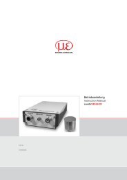
Installing the Encoder<br />
Make sure that the measuring <strong>wire</strong> is always tensioned by the spring<br />
motor in order to prevent it from jumping off the pulley.<br />
3x M3x10 DIN 912<br />
Flange<br />
Encoder<br />
Mounting of adapter flange and encoder, Series WDS-Z60<br />
Mount the encoder/adapter flange assembly on the <strong>draw</strong>-<strong>wire</strong> mechanism.<br />
Fasten the co<strong>up</strong>ling and the encoder shaft with the s<strong>up</strong>plied hexagon<br />
socket screw. Press the s<strong>up</strong>plied cap into the opening in the adapter<br />
flange housing.<br />
i<br />
Make sure that the encoder shaft is not rotated during installation!<br />
Follow the installation <strong>instructions</strong> issued by the manufacturer of the<br />
encoder.<br />
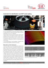
Synchro flange<br />
3xM4 screws DIN7985<br />
with serrated lock washers<br />
4xM4 cylinder screws DIN912,<br />
with serrated lock washers<br />
Co<strong>up</strong>ler Rotex GS<br />
with grub screw M3<br />
Elastomer<br />
co<strong>up</strong>ler<br />
Rotary<br />
encoder<br />
Mounting of adapter flange and encoder, Series WDS-Pxxx
approx. 144 (approx. 5.67 )<br />
115<br />
(4.53)<br />
50 (1.97)<br />
ø30<br />
ø20.2<br />
(0.8 dia.)<br />
(1.18 dia)<br />
115<br />
(4.53)<br />
after 120°<br />
3x ø4.3 (0.17 dia.)<br />
4x Screw<br />
M4x6 DIN 912<br />
4x serrated lock<br />
washer DIN 6798A<br />
60<br />
(2.36)<br />
Hole circle ø42±0.1<br />
(1.65 dia±0.1)<br />
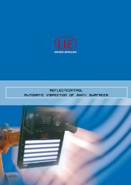
WDS-P115-M, dimensions in mm (inches), not to scale<br />
ø58 (2.28)<br />
ø50 (1.97)<br />
25.7 (1.01)<br />
A<br />
2x Locking screw M4<br />
2x Groove stone 4x Fixing holes M4<br />
B<br />
36<br />
(1.42)<br />
200 (7.87)<br />
ø20.2<br />
ø30<br />
(1.18)<br />
2.8<br />
(0.11)<br />
A<br />
4 (1.42)<br />
1<br />
(0.04) B 21.2<br />
(0.83)<br />
79.5 (3.13)<br />
4 x M4<br />
3x ø4.3<br />
ø42<br />
(1.65)<br />
ø58<br />
(2.28 dia.)<br />
A<br />
Detail A<br />
+0 012<br />
ø6H7 0<br />
(0.24 dia.)<br />
ø50 0<br />
(1.97 dia.)<br />
+0.05<br />
4 (0.16)<br />
10.5±0.5<br />
(0.41)±0.5<br />
Measuring range A B<br />
5000 28 (1.10) 82.5 (3.25)<br />
7500 37 (1.46) 105.5 (4.15)<br />
10000 44.5 (1.75) 148.5 (5.85)<br />
15000 61 (2.40) 180.5 (7.11)<br />
Measuring range A B<br />
30000 268 (10.6) 75 (2.95)<br />
40000 300 (11.8) 95 (3.74)<br />
50000 333.5 (13.1) 95 (3.74)<br />
WDS-P200-M, dimensions in mm (inches), not to<br />
scale<br />
+0 012<br />
0<br />
+0.05<br />
0<br />
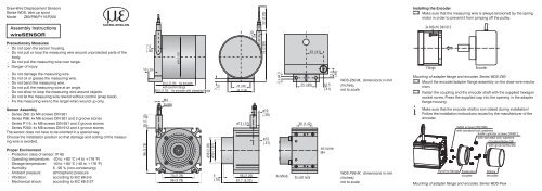
Wire Guide and Fastening<br />
If the measuring <strong>wire</strong> has to be extracted from the <strong>sensor</strong> to guide the <strong>wire</strong><br />
resp. to fix it to the target<br />
--<br />
the <strong>sensor</strong> may not be held by another person<br />
--<br />
the measuring <strong>wire</strong> may not be further extracted but only to the specified<br />
measuring range<br />
--<br />
the surroundings of the <strong>sensor</strong> have to be protected against snapping<br />
of the measuring <strong>wire</strong><br />
Fix the measuring <strong>wire</strong> to the<br />
target using a M4 threaded<br />
bolt or eyelet.<br />
Fed the measuring <strong>wire</strong> perpendicularly<br />
from the <strong>sensor</strong><br />
housing.<br />
Misalignment is only permissible <strong>up</strong><br />
to 3 degrees.<br />
Dragging of the measuring <strong>wire</strong> on<br />
the inlet hole or other objects leads<br />
to damage and/or snapping of the<br />
measuring <strong>wire</strong>.<br />
If the measuring <strong>wire</strong> cannot be fed<br />
vertically out of the housing, it is<br />
essential to use a guide pulley (accessory<br />
TR1-WDS or TR3-WDS).<br />
Keep the measuring <strong>wire</strong><br />
in an area, where it cannot<br />
be snagged or otherwise<br />
violated.<br />
max. 3 °<br />
Wire outlet 0 °<br />
±3 ° tolerancy<br />
Wire fastening and misalignment<br />
For further information, please refer to the online documentation.<br />
You will find the latest version at:<br />
www.micro-epsilon.com/link/<strong>wire</strong><br />
> “Draw-<strong>wire</strong> <strong>sensor</strong> mechanics for mounting encoders“.<br />
Operation and Maintenance<br />
Do not grease or oil the measuring <strong>wire</strong>, the <strong>wire</strong> drum, the spring<br />
motor. Observe the notes on <strong>wire</strong> guiding during operation.<br />
Imperfect <strong>wire</strong> guiding can lead to increased wear and premature defects.<br />
We advise against attempting to do repairs because of the danger of injury<br />
and improper handling. The warranty and all liability claims are null and<br />
void if the device is manipulated by unauthorised persons.<br />
Repairs are to be made exclusively by MICRO-EPSILON.<br />
Declaration of incorporation<br />
MICRO-EPSILON MESSTECHNIK<br />
GmbH & Co. KG<br />
Königbacher Straße 15<br />
94496 Ortenburg / Germany<br />
Declaration of incorporation as defined by the EC Directives Machinery<br />
2006/42/EC, Annex II, section B<br />
We herewith declare that the partly completed machinery<br />
Type of machinery: <strong>wire</strong><strong>sensor</strong>,<br />
Type/Model: WDS-xxx, WPS-xxx<br />
fulfills the relevant essential requirements of the EC Directives Machinery<br />
2006/42/EC.<br />
Furthermore, we declare that the relevant technical documentation for this<br />
partly completed machinery is prepared as described in Annex VII, part B.<br />
We commit ourselves to transmit the relevant technical documentation to<br />
the national authorities on request.<br />
The partly completed machinery must not be put into service until the machinery<br />
into which it is to be incorporated has been declared in conformity<br />
with the provisions of the EC Machinery Directives and for which a declaration<br />
of conformity exists referred to Annex II A.<br />
Ortenburg, April 15th 2009<br />
*X9771136-A03*<br />
Dipl.-Phys. Johann Salzberger<br />
Managing Director<br />
X9771136-A031084GBR