Manual optoNCDT ILR 1181-1182 - Micro-Epsilon
Manual optoNCDT ILR 1181-1182 - Micro-Epsilon
Manual optoNCDT ILR 1181-1182 - Micro-Epsilon

Create successful ePaper yourself
Turn your PDF publications into a flip-book with our unique Google optimized e-Paper software.
Instruction <strong>Manual</strong><strong>optoNCDT</strong> <strong>ILR</strong> <strong>1181</strong> / <strong>1182</strong><strong>ILR</strong> <strong>1181</strong>-30<strong>ILR</strong> <strong>1182</strong>-30
MICRO-EPSILONMESSTECHNIKGmbH & Co. KGKönigbacher Strasse 1594496 Ortenburg / GermanyTel. 08542/168-0Fax 08542/168-90e-mail info@micro-epsilon.dewww.micro-epsilon.comCertified acc. to DIN EN ISO 9001: 2008
<strong>optoNCDT</strong> <strong>ILR</strong> <strong>1181</strong> / <strong>1182</strong>Contents1. Safety........................................................................................................................................... 51.1 Symbols Used.................................................................................................................................................... 51.2 Warnings............................................................................................................................................................. 51.3 Notes on CE Identification.................................................................................................................................. 61.4 Proper Use.......................................................................................................................................................... 71.5 Proper Environment............................................................................................................................................ 72. Laser Class................................................................................................................................. 73. Functional Principle, Technical Data.......................................................................................... 94. Delivery...................................................................................................................................... 124.1 Supplied Items, Unpacking.............................................................................................................................. 124.2 Storage............................................................................................................................................................. 125. Installation................................................................................................................................. 135.1 Sensor Mounting.............................................................................................................................................. 135.2 Reflector Mounting........................................................................................................................................... 145.3 Electrical Connections...................................................................................................................................... 155.3.1 <strong>ILR</strong> <strong>1181</strong>-30....................................................................................................................................................... 165.3.2 <strong>ILR</strong> <strong>1182</strong>-30....................................................................................................................................................... 176. Operation................................................................................................................................... 186.1 RS232............................................................................................................................................................... 196.2 RS422............................................................................................................................................................... 206.3 Digital Switching Output .................................................................................................................................. 216.4 Analog Output.................................................................................................................................................. 236.5 Trigger Input..................................................................................................................................................... 257. Control Commands................................................................................................................... 267.1 Command Review............................................................................................................................................ 267.2 Modes............................................................................................................................................................... 287.2.1 DT......Distancetracking..................................................................................................................................... 287.2.2 DS ...... 7 m Distance Tracking......................................................................................................................... 287.2.3 DW......Distance Tracking with Cooperative Target (10 Hz)............................................................................. 297.2.4 DX......Distance Tracking with Cooperative Target........................................................................................... 29
7.2.5 DF......Distance Measurement with External Trigger........................................................................................ 297.2.6 DM......Distance Measurement......................................................................................................................... 307.3 Parameter......................................................................................................................................................... 307.3.1 TP.......Internal Temperature.............................................................................................................................. 307.3.2 SAx......Display/Set Average Value .................................................................................................................. 307.3.3 SDd......Display/Set Display Format................................................................................................................. 317.3.4 STx......Display/Set Measuring Time................................................................................................................ 317.3.5 SFx.x.....Display/Set Scale Factor.................................................................................................................... 327.3.6 SEx......Display/Set Error Mode ....................................................................................................................... 337.3.7 ACx.x.....Display/Set ALARM Center................................................................................................................ 337.3.8 AH......Display/Set ALARM Hysterese.............................................................................................................. 337.3.9 AWx.x......Display/Set ALARM Width................................................................................................................ 347.3.10 RBx.x.....Display/Set Distance of Lout=4mA................................................................................................... 347.3.11 REx.x.....Display/Set Distance of Lout=20mA................................................................................................. 347.3.12 RMx y.y z......Remove Measurement................................................................................................................ 357.3.13 TDxy......Display/Set Trigger Delay, Trigger Level ........................................................................................... 367.3.14 TMx y......Display/Set Trigger Mode, Trigger Level .......................................................................................... 377.3.15 BRx......Display/Set Baud Rate ........................................................................................................................ 387.3.16 AS....Display/Set Autostart Command ............................................................................................................ 387.3.17 OFx.x.....Display/Set Distance Offset............................................................................................................... 397.3.18 SO......Set Current Distance to Offset .............................................................................................................. 397.3.19 PA......Display Settings..................................................................................................................................... 407.3.20 PR......Reset Settings........................................................................................................................................ 418. Hyperterminal............................................................................................................................ 429. Online Help Tool........................................................................................................................ 4510. Troubleshooting........................................................................................................................ 4611. Warranty.................................................................................................................................... 4812. Decommissioning, Disposal..................................................................................................... 4813. Factory Setting.......................................................................................................................... 4914. Maintenance.............................................................................................................................. 50<strong>optoNCDT</strong> <strong>ILR</strong> <strong>1181</strong> / <strong>1182</strong>
Safety1.SafetyThe handling of the sensor assumes knowledge of the instruction manual.1.1Symbols UsedThe following symbols are used in this instruction manual:i1.2WarningsIndicates a hazardous situation which, if not avoided, may result in minor or moderateinjury.Indicates a situation which, if not avoided, may lead to property damage.Indicates a user action.Indicates a user tip.Caution - use of controls or adjustments or performance of procedures other than those specified herein mayresult in hazardous radiation exposure.Avoid unnecessary laser radiation to be exposed to the human body.-- Switch off the sensor for cleaning and maintenance.-- Switch off the sensor for system maintenance and repair if the sensor is integrated into a system.Safety devices must not be defeated or otherwise rendered ineffective.>>Danger of injuryRefrain from using the sensor in an explosive environment.>>Damage to or destruction of the sensor and/or other proximate equipmentCable connectors must not be plugged or unplugged, as long as voltage is supplied. Remember to turn voltagesupply off before you begin working on cable connections.>>Damage to or destruction of the sensor<strong>optoNCDT</strong> <strong>ILR</strong> <strong>1181</strong> / <strong>1182</strong>Page 5
Safety<strong>optoNCDT</strong> <strong>ILR</strong> <strong>1181</strong> / <strong>1182</strong>Avoid banging and knocking the sensor.>>Damage to or destruction of the sensorProtect the cables against damage.>>Failure of the measuring deviceDo not turn the module on if there is fogging or soiling on its optical parts.>>Failure of the measuring deviceDo not touch any of the module’s optical parts with bare hands. Proceed with care when removing dust orcontamination from optical surfaces.>>Failure of the measuring deviceiInformation and warning signs must not be removed.1.3Notes on CE IdentificationThe following applies to <strong>ILR</strong> <strong>1181</strong>/<strong>1182</strong>: EMC regulation 2004/108/ECProducts which carry the CE mark satisfy the requirements of the EMC regulation 2004/108/EC‘Electromagnetic Compatibility’ and the European standards (EN) listed therein. The EU declaration of conformityis kept available according to EU regulation, article 10 by the authorities responsible atMICRO-EPSILON MESSTECHNIKGmbH & Co. KGKönigbacher Straße 1594496 OrtenburgThe sensor is designed for use in industry and satisfies the requirements of the standards-- EN 61326-1: 2006-- EN 61010-1: 2001The system satisfy the requirements if they comply with the regulations described in the instruction manualfor installation and operation.Page 6
Safety1.4Proper Use-- The sensors are be used for• displacement measurement• for special measuring functions--The measuring system may only be operated within the limits specified in the technical data, see Chap. 3.-- The sensors may only be used in such a way that does not endanger persons or cause damage to themachine due to malfunctions or total failure of the sensor.-- Additional precautions for safety and damage prevention must be taken for safety-related applications.1.5 Proper Environment-- Protection class: IP 65-- Operating temperature: -10 to +50 °C (+14 to +122 °F)-- Storage temperature: -20 to +70 °C (-4 to +158 °F)-- Humidity: < 65 % (no condensation)-- Ambient pressure: atmospheric pressure2. Laser ClassThe <strong>optoNCDT</strong> <strong>ILR</strong> <strong>1181</strong>-30/<strong>1182</strong>-30 sensors operates with a wavelength of 650 nm (visible, red). The maximumoptical output is ≤ 1 mW. The sensors are classified in Laser Class 2 (Class II).Class 2 (II) lasers are not notifiable and a laser protection officer is not required either.The housing of the optical sensors may only be opened by the manufacturer. For repair and service purposesthe sensors must always be sent to the manufacturer.The laser warning labels for Germany have already been applied. Those for other non German-speakingcountries an IEC standard label is included in delivery and the versions applicable to the user‘s country mustbe applied before the equipment is used for the first time.The following warning label is attached on the sensor housing (top side):<strong>optoNCDT</strong> <strong>ILR</strong> <strong>1181</strong> / <strong>1182</strong>Page 7
Laser ClassLASER RADIATIONDO NOT STARE INTO BEAMCLASS 2 LASER PRODUCTIEC 60825-1: 2007P1 mW =650 nm t=0.9 ns f=1.2 GHzTHIS PRODUCT COMPLIESWITH FDA REGULATIONS21CFR 1040.10 AND 1040.11iIEC labelOnly for USAIf both warning labels are disguised in operation mode the user must add additional warning labels.During operation of the sensor the pertinent regulations according to EN 60825-1 on “radiation safety of laserequipment“ must be fully observed at all times. The sensor complies with all applicable laws for the manufacturerof laser devices.Although the laser output is low looking directly into the laser beam must be avoided. Due to the visible lightbeam eye protection is ensured by the natural blink reflex.Do not look directly into the laser beam!Close your eyes or turn away promptly if laser radiation strikes your eyes.i<strong>optoNCDT</strong> <strong>ILR</strong>THIS PRODU T COMPLIESW TH FDA REGUL TIONS21CFR 1040.10 AND 1040.11ASER RAD AT ONDO NOT TARE NTO B AMCLASS 2 ASER PRODUCTIEC 60825-1: 2007P1 mW =650 nm t=0 9 ns f=1.2 HzFig. 1 True reproduction of the sensor with its actual location of the warning labels<strong>optoNCDT</strong> <strong>ILR</strong> <strong>1181</strong> / <strong>1182</strong>Page 8
Functional Principle, Technical Data3. Functional Principle, Technical DataThe <strong>optoNCDT</strong> <strong>ILR</strong> <strong>1181</strong>/<strong>1182</strong> is a laser range finder to measure distances from 0.1 m up to 150 m withpinpoint accuracy. A given target can be clearly identified with the help of a red laser sighting point. In termsof operating reach, the <strong>optoNCDT</strong> <strong>ILR</strong> <strong>1181</strong>/<strong>1182</strong> performs depending on the reflectance, morphology andqualities of the target to be measured.The range finder works based on comparative phase measurement. It emits modulated high-frequency lightwhich is diffusely reflected back from the target with a certain shift in phase to be compared with a referencesignal. From the amount of phase shift, a required distance can then be determined with millimeter accuracy.A distance measuring cycle can be triggered in four different ways:-- By sending a command from the PC or another equivalent control unit-- By making appropriate prior parameter settings for the autostart command and applying supply voltage-- By external triggering (in remote-trigger mode)-- Using the autostart trigger function.For a more detailed description of these four trigger options, see Chap. 7.Special performance features are:-- Provides high accuracy and great reach under extreme outdoor temperatures.-- Works in a wide range of operating voltages from 10 VDC to 30 VDC from an onboard vehicle supplypoint, an industrial direct voltage supply net or a DC power pack.--Features consistently low power consumption of < 1.5 W (without I ). Alarm-- Up to 30 m reach for distance measurement, up to 150 m if additional reflectors are mounted onto thetarget (depending on reflectance and environmental conditions).-- Visible laser beam for easier sighting.-- RS232/422 interface port for input of measuring functions and commands from, and output of measuredvalues to, a PC or a laptop.-- Switching output and analog output are separately programmed.-- Switching output with adjustable limit to indicate positive and negative excession of preselectable distancerange window by sighting distance.--Measured values can be displayed in meters, decimeters, centimeters, feet, inches due to.-- Option for remote triggering of a measurement from an external trigger device.<strong>optoNCDT</strong> <strong>ILR</strong> <strong>1181</strong> / <strong>1182</strong>Page 9
Functional Principle, Technical DataThe sensor measures the distance to moving and static targets:-- in the range of 0.1 ... 50 m on diffuse surfaces,-- between 50 m and 150 m on reflectors.12-pole M16 flange-mountconnectorEqualizer tube at front coverwith sender/- receiver opticsInstallation slot formountingFig. 2 Elements of a sensorTechnical dataModel <strong>ILR</strong> <strong>1181</strong>-30 / <strong>ILR</strong> <strong>1182</strong>-30Measuring range 1Linearity 2ResolutionRepeatability0.1 … 50 m on natural, diffuse reflective surfaces,up to max. 150 m on reflection board±2 mm (+15°C … +30°C), ±5 mm (-10 °C … +50 °C)±2 mm ( +59 °F ...+86 °F), ±5 mm ( +14 °F ...+122 °F)0.1 mm≤ 0.5 mmResponse time 1 100 ms ... 6 s (<strong>ILR</strong> <strong>1181</strong>-30) 20 ms ... 6 s (<strong>ILR</strong> <strong>1182</strong>-30)Laseracc. to IEC 825-1 / EN 60825Laser divergencyRed 650 nm, laser safety class 2, power output ≤ 1 mWBeam diameter < 11 mm in 10 m distanceBeam diameter < 35 mm in 50 m distanceBeam diameter < 65 mm in 100 m distance0.6 mrad<strong>optoNCDT</strong> <strong>ILR</strong> <strong>1181</strong> / <strong>1182</strong>Page 10
Functional Principle, Technical DataModel <strong>ILR</strong> <strong>1181</strong>-30 / <strong>ILR</strong> <strong>1182</strong>-30Operating temperatureStorage temperatureTrigger inputSerial interfaceDigital data rateOperating mode-10 °C … +50 °C ( +14 °F ... to +122 °F)-20 °C … +70 °C (-4 °F ... to +158 °F)Trigger edge and –delay adjustable, Trigger pulse max 24 VRS232 oder RS422, Sensor setup is effected about these interfacesadjustable, max 38,4 kBaudIndividual measurement, external trigger, distance tracking, continuousmeasurementAnalog output 4 mA … 20 mA (16 bit DAC), Load ≤ 500 Ohm, temperature drift max. 50ppm/KSwitching output Open Collector, HIGH = U V– 2 V, LOW < 2 V, rated for loads up to 0.5A, switching threshold, latitude (width) and hysteresis free selectable,invertablePower supplyMax. power consumption10 … 30 VDC< 1.5 W, no-load stateConnection 12-pole (Binder series 723)Protection class IP 65DimensionsHousing materialWeight210 mm x 99 mm x 51 mmExtruded aluminum profile with powder-coat paint finish980 gEMC EN 61326-1: 2006 and EN 61010-1: 20011conditional on target reflectance, ambient light influences and atmospheric conditions2statistic controller 95 %<strong>optoNCDT</strong> <strong>ILR</strong> <strong>1181</strong> / <strong>1182</strong>Page 11
Delivery4. Delivery4.1 Supplied Items, Unpacking1 Sensor <strong>optoNCDT</strong> <strong>ILR</strong> <strong>1181</strong>-30/<strong>1182</strong>-301 Instruction manualOptional accessories, separately packed:1 Power supply-/output cable PC11xx with 2 m up to 30 m length (subject to order).1 PC1100-3/RS232 Power supply-/output cable-RS232, with 3 m length1 Female cable connectorCheck for completeness and shipping damage immediately after unpacking. In case of damage or missingparts, please contact the manufacturer or supplier.4.2StorageStorage temperature: - 20 up to +70 °C ( -4 up to +158 °F)Humidity: < 65 % (non-condensing)<strong>optoNCDT</strong> <strong>ILR</strong> <strong>1181</strong> / <strong>1182</strong>Page 12
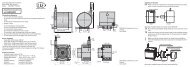
Installation5. InstallationThe sensor <strong>optoNCDT</strong> <strong>ILR</strong> <strong>1181</strong>-30/<strong>1182</strong>-30 is an optical sensor for measurements with millimeter accuracy.Make sure it is handled carefully when installing and operating.5.1Sensor MountingThe sensor is be mounted by means of 4 screws type M6 DIN 934 and two groove stones in the installationslots. The laser beam must be directed perpendicularly onto the surface of the target. In case of misalignmentit is possible that the measurement results will not always be accurate.The sensor will be aligned by a visible laser beam with the target. To align the sensor, please comply with the“Instructions for Operation“, see Chap. 6.17.5(.69)194 (7 64)144 (5.67)41.9(1.65)51 (2.0)25.5(1.0)7.3(0.29)84.4 (3 32)99 (3.88)ø50(1.97)16(.63)M6slot nuts36(1.42)56 (2 2)Fig. 3 Dimensional drawing sensor, dimensions in mm, not to scale<strong>optoNCDT</strong> <strong>ILR</strong> <strong>1181</strong> / <strong>1182</strong>Page 13
Installation194 (7.64)144 (5.67)7( 27)Fig. 4 Offset against zero-edgeThe sensor zero-point is located 7 mm behind the outer surface of the front cover or 137 mm before the backcover outside face respectively. This zero-point has been introduced for constructional design reasons. It canbe compensated with the help of parameter “OF“, see Chap. 7.3.17.5.2Reflector MountingThe sensor measures the distance to moving and static targets:-- in the range of 0.1 ... 50 m on diffuse surfaces,-- between 50 m and 150 m on reflectors (for example reflector film from 3M, Scotchlite Engineer Grade typeI, series 3290).It is possible to align the sensor using the measuring laser. When aligning check as follows:Move the sensor at a very short distance to the reflector (for example < 1 m). The light spot is aligned inthe centre of the reflector.Move the sensor with the longest range to the reflector. Check the position of the light spot at the reflectorand set it if necessary.The light spot must always be in the centre of the reflector whatever the position.<strong>optoNCDT</strong> <strong>ILR</strong> <strong>1181</strong> / <strong>1182</strong>Page 14
InstallationReflectorReflectorReflectorFig. 5 Sensor orientation at reflector filmAvoid exposed cableends.So you prevent anykind of shorts.The wiring of outputswith input signalscan damage thesensor!5.3Electrical ConnectionsLocated on the back cover is a connector terminal. A 12-pole round-type (flangemount) series 723 connectorfrom Binder has been selected for this purpose. It is sealed against the casing to comply with IP 65 requirements.This connector type guarantees optimized screening and a high IP degree. The required counterpart is anadequate female cable connector with grading ring, available as an optional accessory.The PC11x cable set with open ends is optionally available.Bending radius of the supply and output cable PC11x (available as an optional accessory):-- 47 mm (once)-- 116 mm (permanent)<strong>optoNCDT</strong> <strong>ILR</strong> <strong>1181</strong> / <strong>1182</strong>Page 15
InstallationPin Color Assignment<strong>ILR</strong> 118x-30(01)/RS232 <strong>ILR</strong> 118x-30(01)/RS422A white TxD RX+B brown RxD RX-C green TRIGD yellow signal I OUT(4 ... 20 mA)E grey --- TX-F pink --- TX+G red power supply 10 ... 30 VDCH black alarm/digital switching outputJ violet signal groundK grey/pink n.c.L red/blue power supply groundM blue n.c.KJABHLMCDEFGview on solder pin side, 12-polefemale cable connectorFig. 6 Pin assignment“Ground“ wires are connected to an internal collective ground point. They provide the reference potential forall voltage values quoted below.The limiting values of voltages, load rates and logic levels are in accordance with RS232 and RS422 standardrequirements. All outputs are protected against steady short-circuit currents.A power supply and output cable extension is possible. One should, however, observe some important rules,depending on the particular application scenario:5.3.1 <strong>ILR</strong> <strong>1181</strong>-30Keep the RxD and TxD data lines as short as possible in all cases, because they tend to have an interferenceemitting and interference receiving effect, notably, when in open state. Especially in environments with strongspurious radiation there may be faults that may in some cases require a reset (turning the sensor off and onagain).If the RS232 interface communication is not required after parameterization, you should provide for a terminationwiring.<strong>optoNCDT</strong> <strong>ILR</strong> <strong>1181</strong> / <strong>1182</strong>Page 16
InstallationwhiteTxDbrown RxDvioletGND3 kOhm 2.2 nFFig. 7 Recommended termination wiring for work with open RS2325.3.2<strong>ILR</strong> <strong>1182</strong>-30Extension and termination according to standard requirements.For correct screening, three essential rules must be followed:1 For integration with vehicles: Where the attachment point and the reference potential (GND or “-“) haveequal potentials, it may be necessary to electrically isolate the sensor housing, in order to preventground loops.2 Use screened cables, for example “10XAWG224CULSW“. Extend also the cable screen.3 Connect the screen to the ground of the power supply on cable end.1 2 3U vGNDGNDFig. 8 Correct screening of <strong>ILR</strong> <strong>1181</strong>/<strong>1182</strong><strong>optoNCDT</strong> <strong>ILR</strong> <strong>1181</strong> / <strong>1182</strong>Page 17
Operation6. OperationProtect all cable ends before you turn on the power supply. So you avoid shorts.Connect cable connections as required for the particular operating mode.For starting up, a PC with RS232 or RS422 data interface and a terminal program such as the HyperTerminal®are required.Install the sensor as part of preparative actions in the designated working site, oriented onto the targetand keep it in a stable position. The target to be measured should preferentially have a homogeneous,white surface.ReflectorReflectorReflectorFig. 9 Measurement against a reflectorThe sensor provides a visible laser beam for greater convenience in alignment. This laser beam can easilybe turned on at the PC. Its visibility is conditional on the amount of ambient light present and on the type ofsurface of the target to be measured.<strong>optoNCDT</strong> <strong>ILR</strong> <strong>1181</strong> / <strong>1182</strong>Page 18
Operation6.1<strong>optoNCDT</strong> <strong>ILR</strong> <strong>1181</strong> / <strong>1182</strong>RS232Initially, RS232 communication interfaces purely functioned as PC communication ports. They have becomethe established standard tool for serial data transmission over short cable lengths. With greater transmissionthe interface is highly susceptible to interferences, notably, in the vicinity of strong electromagnetic noiseemitters.Therefore, it should only be used for sensor configuration.Parameter-- Baud rate: 9.6 kBaud (2.4 / 4.8 / 19.2 / 38.4) - Start/Stop bit: 1-- Data bits: 8- Handshake: none-- Parity: none- Protocol: ASCIIProperties:-- Maximum input voltage RxD = ±25 V-- Output voltage TxD = 5 VFig. 10 Diagram of RS232 wiring at 9-pole D-Sub female cable connectorFig. 11 Diagram of RS232 wiring at 25-pole D-Sub female cable connectoriShieldTxD>> 2 3white 5brownvioletredred/blue
Operation6.2RS422For configuration purposes and permanent data transmissions over a greater length, the RS422 can be used.This type of interface is insusceptible to interference and noise influences and qualifies for industrial use.Where twisted cable pairs are involved, transmissions lengths up to 1200 m can be handled.Properties:-- Maximum input voltage RX+, RX- = ±14 V-- Output voltage TX ±2 V, 2 x 50 W load differentialwh tebrownredred/blueU VGNDgraypinkFig. 12 Wiring diagram RS422iThe RS422 interface is popular in industrial applications. Use an adequate USB TO RS422 converter ora RS422 interface card in the case of your PC/ notebook is just equipped with USB interfaces.<strong>optoNCDT</strong> <strong>ILR</strong> <strong>1181</strong> / <strong>1182</strong>Page 20
Operation6.3 Digital Switching OutputProperties: Open collector--HIGH = U – 2 V V-- LOW < 2 V-- rated for loads up to 0.5 A-- with switching threshold, latitude (width) and hysteresis selectableblackI L= 10 ... 500 mAredred/blueU VGNDFig. 13 Wiring diagram of digital switching outputFor example, using the digital switching output, an object which was selected for measurement can bemonitored for excession of a threshold value. To do this, parameter settings for a measurement window arerequired. Settings for this window can be made via the three parameters: Alarm Center (AC), Alarm Hysteresis(AH) and Alarm Width, see Chap. 7.3.7 et seq..The range which will be subject to monitoring begins at AC and ends at AC+AW. Switching transitions can beset via parameter AH. The logic state of the switching output follows from the mathematical sign of AH. In thecase of a positive AH, the output switches-- with increasing distance:• from LOW to HIGH if the distance is found to be greater than (AC + AH/2).• from HIGH to LOW if the distance is found to be greater than (AC + AW + AH/2)- with decreasing distance:• from LOW to HIGH if the distance is found to be smaller than (AC + AW - AH/2).• from LOW to HIGH the distance is found to be smaller than (AC - AH/2).In the case of a negative AH, the output switching pattern will be inverse.<strong>optoNCDT</strong> <strong>ILR</strong> <strong>1181</strong> / <strong>1182</strong>Page 21
Operation+AH -AHHIGH LOWAHAHLOW HIGHACAWDist.Fig. 14 Digital switching output behavior with positive and negative hysteresisExample:A moving object is assumed to be monitored within a window of 10 m to 11 m with a hysteresis of 0.2 m.Consecutively you find the parameters AC, AW and AH in dependence on SF:-- AC2 / AH0.2 / AW3 / SF1-- AC2000 / AH200 / AW3000 / SF1000Distance (m) increases1.8 1.9 2.0 2.1 2.2 ... 5.0 5.1 5.2+AH L L L H H H H L L-AH H H H L L L L H HDistance (m) decreases5.2 5.1 5.0 4.9 4.8 ... 2.0 1.9 1.8+AH L L L L H H H H L-AH H H H H L L L L HL = LOW, H = HIGHHow the switching output is to behave on occurrence of an error message (E15, E16, E17, E18) can be definedby making suitable settings under “SE“, see Chap. 7.3.6.<strong>optoNCDT</strong> <strong>ILR</strong> <strong>1181</strong> / <strong>1182</strong>Page 22
Operation6.4 Analog OutputProperties: Current output-- 4 mA...20 mA-- Distance range limits can be set-- Behavior on error report can be preselected: 3 mA or 21 mA-- Load resistance: ≤ 500 Ω against GND-- Accuracy: ±0.15 %-- Max. temperature drift: 50 ppm/K-- Resolution: 16 bit DA-converterredred/blueyellow4 ... 20 mAR L≤ 500 ΩU VGNDFig. 15 Wiring diagram of analog outputThe purpose of the analog output is to allow transmission of analog measured values via a 4 ... 20 mA interface.The amount of current which is injected into the line of transmission is proportional to the distance measured.A given range of distances can be selected for transmission via the two parameters Range Beginning (RB)and Range End (RE), see Chap. 7.3.10, see Chap. 7.3.11.RE may be greater or smaller than RB.The amount of injected current can be calculated as follows:-- RE > RB: IOUT [mA] = 4 mA + 16*((Distance - RB) / (RE - RB)) mA-- RE < RB: IOUT [mA] = 20 mA - 16*((Distance - RE) / (RB - RE)) mA<strong>optoNCDT</strong> <strong>ILR</strong> <strong>1181</strong> / <strong>1182</strong>Page 23
OperationCurrent out of distance range:Dist. < (RB..RE) Dist. > (RB..RE)RE > RB 4 mA 20 mARE < RB 20 mA 4 mAOn occurrence of an error message (E15, E16, E17, E18), the output current can be matched to 3 mA or21 mA with the help of parameter SE, see Chap. 7.3.6.I out[mA]2120SE=2RB>RERB RB and RE < RBExamples:The distance of a moving target is to be measured in a range of 2 m up to 6 m. At a distance of 2 m the sensoris to output 4 mA. You find the parameter RB and RE against SF below:-- RB2 / RE6 / SF1The distance of a moving target is to be measured in a range of 1 m up to 21 m. At a distance of 1 m the sensoris to output 20 mA. You find the parameter RB and RE against SF below:-- RB21000 / RE1000 / SF1000<strong>optoNCDT</strong> <strong>ILR</strong> <strong>1181</strong> / <strong>1182</strong>Page 24
Operation6.5 Trigger InputProperties:-- Trigger voltage 3 V ... 24 V-- Trigger threshold +1.5 V-- Trigger delay 5 ms + selectable delay time until start of measurement-- Trigger pulse length ≥ 1 ms-- Delay time (trigger delay) selectable from 0 ms to 9999 ms-- Extended trigger function: selectable autostart triggergreenredred/bluemax. 24 VU VGNDFig. 17 Wiring diagram of trigger inputThe trigger input is intended for triggering a distance measurement with an external signal that is applied as avoltage pulse between 3 V and 24 V.Specify a desired delay time and the pulse flank to be selected for synchronization, see Chap. 7.3.13.iSwitch the sensor to trigger mode (DF), see Chap. 7.2.5.Connect the trigger input with +24 V or the ground connection. The input may not remain open definitely.NC at +24 V for L-level-triggerNC at ground for H-level-trigger<strong>optoNCDT</strong> <strong>ILR</strong> <strong>1181</strong> / <strong>1182</strong>Page 25
Control Commands7. Control Commands7.1Command ReviewThe easiest way to trigger and parameterize the sensors is by using a PC with RS232 communication portand a terminal program, see Chap. 8.. The communications protocol is available in ASCII format.Before an operating session begins, desired parameter settings can be made in a smart selection procedureuntil the measuring module is optimally adapted to the particular measuring site conditions and the measuringjob. All valid settings will be preserved on turning the sensor off! They can only be replaced with newvalue entries or changed back to their standard values by running an initialization routine.Kommando BeschreibungIDOnline help to the control commandsDT Starts distance trackingDS Starts distance tracking 7 mDW Starts distance tracking on white target at 10 HzDX Starts distance tracking on white target at 50 Hz (only <strong>ILR</strong> <strong>1182</strong>-30)DF Starts remote-triggered single distance measurement (single shot)DM Starts single distance measurement (single shot)TP Queries inner temperatureSA Queries / sets floating average value (1...20)SD Queries / sets output format (dec/hex)ST Queries / sets time to measure (0...25)SF Queries / sets scale factorSE Queries / sets error mode (0, 1, 2)AC Queries / sets alarm centerAH Queries / sets alarm hysteresisAW Queries / sets alarm widthRB Queries / sets beginning of range (4 mA)RE Queries / sets end of range (20 mA)RM Queries / sets removal of measured valueTD Queries / sets trigger delay<strong>optoNCDT</strong> <strong>ILR</strong> <strong>1181</strong> / <strong>1182</strong>Page 26
Control CommandsTMBRASOFSOPAPRQueries / sets trigger modeQueries / sets baud rateQueries / sets autostartQueries / sets offsetSets current distance as offsetDisplays all parameter valuesResets all parameters to standard valuesFig. 18 Short overview control commandsCommand entries are not case-sensitive. This means that small and capital lettering can be used for commands.Any command which is to be sent to the sensor must be terminated by a hexadecimal 0Dh (carriagereturn) character.Where decimal digits are to be entered, they must be separated by period (2Eh).For command paramater entries, one must distinguish between parameter settings and parameter queries.Querying is achieved with a command in simple format, for example parameter alarmcenter: AC[Enter]. Forparameter setting, a new value must be added after the command with no delimitation sign in between, forexample: AC20.8[Enter]. In the given example, the alarm center will be set to 20.8.<strong>optoNCDT</strong> <strong>ILR</strong> <strong>1181</strong> / <strong>1182</strong>Page 27
Control Commands7.2i7.2.1ModesThe sign ESC (1Bh) finishes the data output. Now the sensor waits for a new command.DT......DistancetrackingEssential input parameters: SA, SD, SE, SF, ST, OFEffect on:RS232/RS422, digital switching output, analog output-- Distance measurement at different kinds of surfaces (varying reflectance).-- Permanent evaluation of the sensitive laser radiation.• changing reflectance: longer measuring time• sudden jumps in distance: longer measuring timeThe minimum time to measure is 160 ms, the maximum time is 6 s. If the measuring signal fails to reach aspecified quality within six seconds, an error message is output.The time to measure may also be limited by setting the ST parameter to a desired value.7.2.2 DS ...... 7 m Distance TrackingEssential input parameters:Effect on:SA, SD, SE, SF, ST, OFRS232/RS422, digital switching output, analog output-- Distance measurement at different kinds of surfaces at close range up to 7 m-- Higher measurement rate compared to DT measuring mode.-- Within the range from 0.1 m to 0.5 m, measuring accuracy is restricted.Measuring time (time to measure) can be limited via ST parameter settings.<strong>optoNCDT</strong> <strong>ILR</strong> <strong>1181</strong> / <strong>1182</strong>Page 28
Control Commands7.2.3DW......Distance Tracking with Cooperative Target (10 Hz)The command is only relevant for the <strong>ILR</strong> <strong>1181</strong>.Essential input parameters:Effect on:SA, SD, SE, SF, OFRS232/RS422, digital switching output, analog output-- Performs at a steady measuring rate of 10 Hz.-- Stable measuring values only with a white target board at the target.-- No sudden jumps in distance > 16 cm.7.2.4DX......Distance Tracking with Cooperative TargetThe command is only relevant for the <strong>ILR</strong> <strong>1182</strong>.Essential input parameters:SA, SD, SE, SF, OFEffect on:RS232/RS422, digital switching output, analog output-- Performs at a steady measuring rate of 50 Hz.-- Stable measuring values only with a white target board at the target.-- Homogeneous motions with maximum 4 m/s.-- High rate of measurement, included preceding measuring values in the process to calculate a currentlymeasuring value.-- No sudden jumps in distance >16 cm.7.2.5 DF......Distance Measurement with External TriggerEssential input parameters:Effect on:SD, SE, SF, ST, OF, TDRS232/RS422, digital switching output, analog output-- Preparation for the single measurement, triggered by an external trigger pulse.Initially, after selecting this mode, the operator does not receive any response. As soon as the trigger pulsehas been detected, the sensor will send data and switches the digital and/or the analog output.The Settings for the trigger delay (delay) and the trigger flank can be defined via parameter TD, see Chap.7.3.13.<strong>optoNCDT</strong> <strong>ILR</strong> <strong>1181</strong> / <strong>1182</strong>Page 29
Control Commands7.2.6 DM......Distance MeasurementEssential input parameters:Effect on:SD, SE, SF, ST, OFRS232/RS422, digital switching output, analog output-- Triggers a single measurement (single shot).7.37.3.1ParameterTP.......Internal TemperatureTP queries the value of the inner sensor temperature in °C.i7.3.2In tracking mode, the inner temperature may exceed the surrounding temperature level by as much as10 K.SAx......Display/Set Average ValueStandard setting: N = 1SA allows you to calculate a floating average value from 1 to 20 measured values.M = avN∑k=1NMW (k)Fig. 19 Formula for the floating average valueMW = Measuring valueN = Quantityk = Current index= Average valueM av<strong>optoNCDT</strong> <strong>ILR</strong> <strong>1181</strong> / <strong>1182</strong>Page 30
Control Commands<strong>optoNCDT</strong> <strong>ILR</strong> <strong>1181</strong> / <strong>1182</strong>MethodEvery new measuring value is added, the first (oldest) measuring value is taken out of the averaging.Example with N = 7:.... 0 1 2 3 4 5 6 7 8 gets to 2+3+4+5+6+7+87Average value n.... 1 2 3 4 5 6 7 8 9 gets to 3+4+5+6+7+8+97Average value n + 17.3.3SDd......Display/Set Display FormatStandard setting: dSD switches between decimal (d) and hexadecimal (h) output format of measured value data. SD affects allcommands that output a distance value.A hexadecimal output value is calculated from a given measured distance value (in mm), multiplied by thescale factor SF.Negative distance values are output in two’s complement notation.Example:Distance = 4.996 m, SF1 dec: 4.996 hex: 001384 (= 4996 mm × SF1)Distance = 4.996 m, SF10 dec: 49.960 hex: 00C328 (= 49960 = 4996 mm × SF10)7.3.4 STx......Display/Set Measuring TimeStandard setting: 0Measuring time is directly conditional on the selected measuring mode. As a general rule, one may say: thepoorer the surface reflectance of a selected target, the longer the sensor will take to determine a given distancewith specified accuracy. For example, if error message E15 is output because of poor reflectance andinsufficient time to measure, this latter setting must be increased.-- Value range ST: 0 ... to 25-- The greater the time setting is the more time will be available for measurement and the lower the resultingmeasuring rate.-- An exception therefrom is zero-value. In this case, the sensor automatically picks the smallest possibletime value for measurement!-- The sensor comes factory-set with ST = 0.Page 31
Control Commands-- ST is effective in the DT, DS, DF and DM modes.The measuring time setting option allows also the modifying of the measuring rate, for example, in order torestrict the data volume or for synchronization purposes.Measuring time can only be set as an approximate value, because the underlying principle of measurementis subject to certain variances that cannot be accounted for:DT measuring mode > measuring time approximately ST x 240 ms (except ST = 0)DS measuring mode > measuring time approximately ST x 150 ms (except ST = 0)Example:The target distance is 25 m, but the target’s reflectance is not ideal. With a measuring time setting of ST 2,E15 will be output following measurement. The user must increase the measuring time in this case!iOne should work in DW or DX mode where stable measuring times are required.7.3.5 SFx.x.....Display/Set Scale FactorStandard setting: 1SF multiplies a calculated distance value with a user-selectable factor for changes in resolution or outputs ina different unit of measure. The scale factor may also be negative.Scale factor Resolution Output Unit of measureSF1 1 mm 02.693 mSF10 0.1 mm 26.931 dmSF1.0936 0.01 yard 02.945 yardSF3.28084 0.01 feet 08.835 feetSF0.3937 1 inch 01.060 100 inchSF-1 1 mm -02.693 mFig. 20 Examples of scale factoriFollowing a change in the scale factor, the settings for digital and/ or analog output and offset must bematched accordingly!<strong>optoNCDT</strong> <strong>ILR</strong> <strong>1181</strong> / <strong>1182</strong>Page 32
Control Commands7.3.6 SEx......Display/Set Error ModeStandard setting: 1SE allows you to configure how the digital switching output (alarm) and/or the analog output is to behave onoccurrence of an error message (E15, E16, E17, E18).Depending on the particular sensor application, different reactions to an error message are possible.Available selection options:SE Digital switching output (ALARM) Analog output (I OUT)0 ALARM of latest valid measurement I OUTof latest valid measurement1 AH: ALARM = LOW-AH: ALARM = HIGH2 AH: ALARM = HIGH-AH: ALARM = LOWFig. 21 Digital switching output and analog output7.3.7 ACx.x.....Display/Set ALARM CenterRE > RB: I OUT= 3 mARE < RB: I OUT= 21 mARE > RB: I OUT= 21 mARE < RB: I OUT= 3 mAStandard setting: 0.1AC sets the beginning of the distance range, for which the switching output will be turned active. The lengthof this active range can be set using the AW parameter.AC must be selected in keeping with the currently set SF scale factor (see Chap. 6.3 Digital switching output).7.3.8 AH......Display/Set ALARM HystereseStandard setting: 0.001AH allows you to make parameter settings for the switching hysteresis at the beginning and the end point ofthe active range of the switching output.-- Set AH so it is properly matched to the currently valid scale factor (SF).-- The mathematical sign of AH affects the setting of an active state logic level:• Positive sign (“+”): active range is HIGH-active.• Negative sign (“-“): active range is LOW-active.• No sign setting means positively-signed, see Chap. 6.3.<strong>optoNCDT</strong> <strong>ILR</strong> <strong>1181</strong> / <strong>1182</strong>Page 33
Control Commands7.3.9AWx.x......Display/Set ALARM WidthStandard setting: 100-- AW sets the length of the active range, beginning at AC.-- Set AW settings in agreement with the currently valid SF scale factor.-- AW is always equal or greater than “0” (zero).--AW is always equal or greater than |AH| (the amount of AH) , see Chap. 6.3.7.3.10 RBx.x.....Display/Set Distance of Lout=4mAStandard setting: 0.1RB (Range Beginning) corresponds to the starting point of the distance range that is provided at the analogoutput.--A distance value = RB will generate a current I of 4 mA.OUT-- Set RB in agreement with the currently valid SF scale factor.-- RB can be greater or smaller!-- Beyond the range that was set via RB and RE, the applied current will be that of the next limiting value.In the event of a fault, the output value will correspond to the current that was set via parameter SE, seeChap. 7.3.6.7.3.11 REx.x.....Display/Set Distance of Lout=20mAStandard setting: 30RE (Range End) corresponds to the end point of the distance range that is provided at the analog output.--A distance value = RE will generate a current I of 20 mA.OUT-- Set RE in agreement of the scale factor SF.-- RE can be greater or smaller as RB!-- Beyond the range that was set via RB and RE, the applied current will be that of the next limiting value.--In the event of a fault, the output value will correspond to the current that was set via parameter SE, seeChap. 7.3.6.<strong>optoNCDT</strong> <strong>ILR</strong> <strong>1181</strong> / <strong>1182</strong>Page 34
Control CommandsThe use of RMparameter settingsshould be restrictedto suitable applicationsonly. Improperuse of this parametermay createsafety hazards!7.3.12RMx y.y z......Remove MeasurementStandard setting: 0 0 0RM is intended to facilitate settings for a range of expected distance values. Values which are found to be outsideof this expected range will be corrected until matching the most recently valid measuring values.RM is only effective in DT mode.It consists of three parameters which are separated by space (20 hex).XDesignates the number of preceding measuring values that will be evaluated in the case of non-conformingmeasurement. A maximum of ten preceding measured values can be evaluated.Y Defines the range of permissible values. If this range is exceeded in negative or positive direction, therespective measuring value will be corrected accordingly.Z Stands for the number of values that are out of the permissible value range; in the event of out-of-tolerancevalues arriving in succession, the most recently corrected value will be included in the correctionprocess for the next out-of-tolerance value.The maximum allowed number of out-of-tolerance values is 100.Example:-- x = 3-- 2y = 0.1-- z = 1<strong>optoNCDT</strong> <strong>ILR</strong> <strong>1181</strong> / <strong>1182</strong>Page 35
Control Commands10.05 (.396)10.00 (.393)9.95 (.392)9.90 (.39)9.85 (.388)9.80 (.386)9.75 (.384)9.70 (.382)9.85(.388)9.83 (.387) x9.88(.389)10 (.393)9.89(.389)9.85(.388)9.86x (.388)Ist-Measurement Korr. run Limit9.88(.389)2y9.77(.385)9.75 (.384)z1 2 3 4 5 6 7 8 9 10Fig. 22 Correction of measuring value7.3.13 TDxy......Display/Set Trigger Delay, Trigger LevelStandard setting: 0 0TD sets up solely the behavioral configuration of the remote trigger input (DF mode, see Chap. 7.2.5).TD consists of two parameters which are separated by space (20 hex):-- the delay time, and-- trigger flange.XYcorresponds to the delay in time from the arrival of a trigger signal to the start of a measurement.Delay settings may range from 0 to 9999 ms.0 for HIGH > LOW transition1 for LOW > HIGH transition<strong>optoNCDT</strong> <strong>ILR</strong> <strong>1181</strong> / <strong>1182</strong>Page 36
Control CommandsExample:TD1000_0[Enter]In the given example, the delay time was set to 1000 ms and the trigger flank to “falling type” (HIGH to LOWtransition).7.3.14TMx y......Display/Set Trigger Mode, Trigger LevelStandard setting: 0 1TM provides parameter the setting option for the auto-start trigger function which allows external triggering ofthe auto-start command that was set via parameter AS.Triggering is accomplished via the external trigger input. All starting modes which are selectable via AS canbe launched and stopped by external triggering. These are: DS/DT/DW/DX/DF/DM/TP/LO/ID.TM consists of two parameters which are separated by space (20 hex).xyi0 ... trigger function turned off1 ... trigger function turned on0 ... measurement is triggered on trigger line at L-level (HIGH > LOW transition)1 ... measurement is triggered on trigger line at H-level (LOW > HIGH transition)The trigger input must be located on a defined level about +24 V or ground.Examples:a) ASDTTM1 1Trigger signal = H > DT is performedTrigger signal = L > DT is stoppedHIGHLOWDT onDT offt<strong>optoNCDT</strong> <strong>ILR</strong> <strong>1181</strong> / <strong>1182</strong>Page 37
Control Commandsb) ASDMHIGHLOWDM onDM off7.3.15TM1 0Trigger signal = H > no change in stateTrigger signal = L > DM active, that means, one measurement is triggeredBRx......Display/Set Baud RatetStandard setting: 9600Available baud rate BR settings are: 2400, 4800, 9600, 19200, 38400.Faulty entries will be rounded to the nearest baud rate.A fixed data format of eight data bits, with no parity and one stop bit is used.After a change in baud rate setting, the communicating counterpart must also be set to the new baudrate.i7.3.16AS....Display/Set Autostart CommandStandard setting: IDAS (autostart) defines which function will be carried out when power becomes available to the sensor. Possibleentries are those delivering a measuring value on the output side, an ID command and the commandfor turning the laser on (LO).For example, if ASDT has been parameterized, the sensor will begin with distance tracking on turning onpower.Possible versions: DT/DS/DW/DX/DF/DM/TP/LO/ID<strong>optoNCDT</strong> <strong>ILR</strong> <strong>1181</strong> / <strong>1182</strong>Page 38
Control Commands7.3.17 OFx.x.....Display/Set Distance OffsetStandard setting: 0With the help of OF (offset) define a zero-point for his/her application. For details on the position of the module’szero-point, see Chap. 5.-- OF must be selected so it is properly matched to the currently valid scale factor setting (SF).-- OF may also take on negative values.7.3.18 SO......Set Current Distance to OffsetSO performs a distance measurement and saves the measured reading as an offset value with inverted mathematicalsign (OF).Result: (offset = - distance)<strong>optoNCDT</strong> <strong>ILR</strong> <strong>1181</strong> / <strong>1182</strong>Page 39
Control Commands7.3.19 PA......Display SettingsPA lists all parameters in a table.Example:average value[SA] 1display format[SD]dmeasure time[ST] 0scale factor[SF] 1error mode[SE] 1ALARM center[AC] 20ALARM hysterese[AH] 0.1ALARM width[AW] 10distance of Iout=4mA [RB] 15distance of Iout=20mA [RE] 25remove measurement [RM] 0 0 0trigger delay, trigger level[TD] 0 0trigger mode, trigger level[TM] 0 1baud rate[BR] 9600autostart command[AS] IDdistance offset[OF] 0<strong>optoNCDT</strong> <strong>ILR</strong> <strong>1181</strong> / <strong>1182</strong>Page 40
Control Commands7.3.20PR......Reset SettingsPR resets all parameters(except for baud rate) to their standard settings.average value[SA] 1display format[SD]dmeasure time[ST] 0scale factor[SF] 1error mode[SE] 1ALARM center[AC] 0.1ALARM hysterese[AH] 0.001ALARM width[AW] 100distance of Iout=4mA [RB] 0.1distance of Iout=20mA [RE] 30remove measurement [RM] 0 0 0trigger delay, trigger level[TD] 0 0trigger mode, trigger level[TM] 0 1baud rate[BR] 9600autostart command[AS] DTdistance offset[OF] 0<strong>optoNCDT</strong> <strong>ILR</strong> <strong>1181</strong> / <strong>1182</strong>Page 41
Hyperterminal8. HyperterminalYou can receive data and configure the controller through the RS232 interface with the Windows HyperTerminal®.All you need is a free COM port (for example COM1) on your PC and the commands described in theforegoing chapters.The RS232 interface are popular in industrial applications. Use an adequate USB TO RS232 converter,in the case of your PC/notebook is just equipped with USB interfaces.iPreparation MeasuringConnect your controller to a free COM port of the host computer.Start the program HyperTerminal® (Menu Start > Programs > Accessory > Communication > Hyper-Terminal)Type in the name of the connection and click on the “OK“ button.Fig. 23 Connection establishment with the program HyperTerminal®Select the interface and click on the “OK“ button.<strong>optoNCDT</strong> <strong>ILR</strong> <strong>1181</strong> / <strong>1182</strong>Page 42
HyperterminalFig. 24 Definition of the serial interfaceFig. 25 Definition of the serial interfaceDefine the following interface parameters:Baud rate: 9.600 BaudData format: 8 Data bitsParity: NoneStart/Stopbit: 1Flow control: NoClick on the “OK“ button.Type the command “ID“ and press the button “EN-TER“The sensor reads out the commands for the distancemeasuring cycle respectively the prior parameter settings,see Fig. 26. With pressing the “ESC“- button thedata output will be finished and the sensor waits forfurther instructions.<strong>optoNCDT</strong> <strong>ILR</strong> <strong>1181</strong> / <strong>1182</strong>Page 43
HyperterminalFig. 26 User interface in terminal operationiA currently entered command will only be displayed if “Local echo“ is enabled. This function can be accessedvia file menu File > Properties > “Settings“ tag > ASCII Setup.Save finally, unless performed earlier, the current hyperterminal configuration. For more convenienceyou don’t have to reconfigure the interface for each new hyperterminal session.<strong>optoNCDT</strong> <strong>ILR</strong> <strong>1181</strong> / <strong>1182</strong>Page 44
Online Help Tool9. Online Help ToolOnce communication has been established with a PC (as described above), an online help tool can be calledup by triggering an ID [Enter] or id [Enter] command at the keypad. Its purpose is to support work withdistance measurement and parameterization commands. [Enter] corresponds to hexadecimal 0D hex(carriagereturn).DT[Enter]distancetrackingDS[Enter]distancetracking 7 mDW[Enter]distancetracking with cooperetive target (10 Hz)DX[Enter]distancetracking with cooperetive target (50 Hz)DF[Enter]distance measurement with external triggerDM[Enter]distance measurementTP[Enter]internal temperature [°C]SA[Enter] / SAx[Enter] display/set average value [1..20]SD[Enter] / SDd[Enter] display/set display format [d/h]ST[Enter] / STx[Enter] display/set measure time [0..25]SF[Enter] / SFx.x[Enter] display/set scale factorSE[Enter] / SEx[Enter] display/set error mode [0/1/2]0..Iout=const., ALARM=const.1..Iout: 3 mA @RE>RB, 21 mA @RE0, ON@AHRB, 3mA @RE0, OFF@AH
TroubleshootingAS[Enter] / ASd[Enter]OF[Enter] / OFx.x[Enter]SO[Enter]PA[Enter]PR[Enter]10.Troubleshootingdisplay/set autostart command [DT/DS/DW/DX/DF/DM/TP/LO/ID]display/set distance offsetset current distance to offset(offset = - distance)display settingsreset settingsCode Description Action for removalE15Excessively poor reflexes; Distance sensor(Front edge) against target < 0.1mUse target board,increase distance between sensor and target.E16 Excessively strong reflexes Use target board.E17 Too much steady light (for example sun) Reduce ambient light at target;reflecting objects remove or cover.E18 Only in DX mode (50 Hz): too much differencebetween measured and pre-calculatedvalueCheck path from distance meter to target beingmeasured for obstacles.E19Only in DX mode (50 Hz):Target motionspeed > 10 m/sReduce motion speed of target respectively of thesensor.E23 Temperature below -10 °C Provide ambient temperature > -10 °CE24 Temperature above +60 °C Provide ambient temperature < +60 °CE31 Faulty EEPROM checksum,hardware errorService required if fault occurs repeatedly--> reship the sensor for repair.E51Failure to set avalanche voltage of diode laser1. straylight or2. hardware error1. Check ambient light radiation; limit ambient light2. Service required --> reship the sensor for repair.E52 Laser current too high / laser defective --> Reship the sensor for repair, contact technicalsupport<strong>optoNCDT</strong> <strong>ILR</strong> <strong>1181</strong> / <strong>1182</strong>Page 46
TroubleshootingE53One or more parameters in the EEPROM notset (Consequence: Division by 0)1. Parameter SF examine (SF must be unequal 0)2. Contact technical support --> reship the sensorfor repair.E54 Hardware error (PLL) Contact technical support --> reship the sensor forrepair.E55 Hardware error Contact technical support --> reship the sensor forrepair.E61 Used parameter is inadmissible, invalid commandCheck control software commands.sentE62 1. Hardware errorCheck external software parity setting.2. wrong value in interface communication(Parity error SIO)E63 SIO overflow Check time of emitted signals in application software;integrate delay on transmission if necessary.E64 Framing-Error SIO Data format of the serial interface examine (8N1)<strong>optoNCDT</strong> <strong>ILR</strong> <strong>1181</strong> / <strong>1182</strong>Page 47
Warranty11.WarrantyAll components of the device have been checked and tested for perfect function in the factory. In the unlikelyevent that errors should occur despite our thorough quality control, this should be reported immediately toMICRO-EPSILON. The warranty period lasts 12 months following the day of shipment. Defective parts, exceptwear parts, will be repaired or replaced free of charge within this period if you return the device free of cost toMICRO-EPSILON.This warranty does not apply to damage resulting from abuse of the equipment and devices, from forcefulhandling or installation of the devices or from repair or modifications performed by third parties. No otherclaims, except as warranted, are accepted. The terms of the purchasing contract apply in full.MICRO-EPSILON will specifically not be responsible for eventual consequential damages.MICRO-EPSILON always strives to supply the customers with the finest and most advanced equipment.Development and refinement is therefore performed continuously and the right to design changes withoutprior notice is accordingly reserved.For translations in other languages, the data and statements in the German language operation manual areto be taken as authoritative.12. Decommissioning, DisposalDisconnect the power supply and output cable on the sensor.The <strong>optoNCDT</strong> <strong>ILR</strong> <strong>1181</strong>/<strong>1182</strong> is produced according to the directive 2002/95/EC (“RoHS“). The disposal isdone according to the legal regulations (see directive 2002/96/EC).<strong>optoNCDT</strong> <strong>ILR</strong> <strong>1181</strong> / <strong>1182</strong>Page 48
Factory Setting13.Factory SettingParameter SettingSA 1SDdST 0SF 1SE 1AC 0.1AH 0.001AW 100RB 0.1iParameter SettingRE 30TD 00BR 9600ASDTOF 0TM 01RM 000Adress Slave no valueAt the parameters AC, AH, TD, TM, RM the values are to separate by space.Decimal tag is a dot (2E hex).The command PR reset all parameters with excepting the baud rate to the standard settings.<strong>optoNCDT</strong> <strong>ILR</strong> <strong>1181</strong> / <strong>1182</strong>Page 49
Maintenance14.MaintenancePlease note:Remove dust from optical surfaces (transmitter and receiver optics) with a blower brush.Do not use cleaners that contain organic solvents, when wiping optical surfaces downContact the manufacturer in the case of stubborn contamination or soiling.-- Do not use solvents of any kind to perform cleaning of the sensor.-- You are prohibited from opening the sensor.-- You are prohibited from loosening any screw at the sensor.For necessary repair work, you should carefully pack the sensor and reship it to MICRO-EPSILON stating theconditions in which it has operated (applications, connections and environmental conditions):MICRO-EPSILON MESSTECHNIKGmbH & Co. KGKönigbacher Strasse 15D-94496 OrtenburgTel. 08542/168-0Fax 08542/168-90e-mail info@micro-epsilon.dewww.micro-epsilon.de<strong>optoNCDT</strong> <strong>ILR</strong> <strong>1181</strong> / <strong>1182</strong>Page 50
MICRO-EPSILON MESSTECHNIK GmbH & Co. KGKönigbacher Str. 15 · 94496 Ortenburg / GermanyTel. +49 (0) 8542 / 168-0 · Fax +49 (0) 8542 / 168-90info@micro-epsilon.de · www.micro-epsilon.comX9751184-A031122HDRMICRO-EPSILON MESSTECHNIK*X9751184-A03*