Manual optoNCDT 1402 - Micro-Epsilon
Manual optoNCDT 1402 - Micro-Epsilon
Manual optoNCDT 1402 - Micro-Epsilon

You also want an ePaper? Increase the reach of your titles
YUMPU automatically turns print PDFs into web optimized ePapers that Google loves.
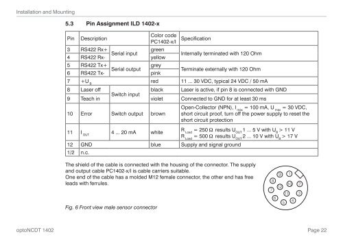
Installation and Mounting5.3 Pin Assignment ILD <strong>1402</strong>-xPin DescriptionColor codePC<strong>1402</strong>-x/ISpecification3 RS422 Rx+ greenSerial input4 RS422 Rx- yellowInternally terminated with 120 Ohm5 RS422 Tx+ greySerial output6 RS422 Tx- pinkTerminate externally with 120 Ohm7 +UBred 11 ... 30 VDC, typical 24 VDC / 50 mA8 Laser offblack Laser is active, if pin 8 is connected with GNDSwitch input9 Teach in violet Connected to GND for at least 30 msOpen-Collector (NPN), I = 100 mA, U = 30 VDC,max max10 Error Switch output brown short circuit proof, turn off the power supply to reset theshort circuit protection11 IOUT4 ... 20 mA whiteR = 250 W results U 1 ... 5 V with U > 11 VLoad OUT BR = 500 W results U 2 ... 10 V with U > 17 VLoad OUT B12 GND blue Supply and signal ground1/2 n.c.The shield of the cable is connected with the housing of the connector. The supplyand output cable PC<strong>1402</strong>-x/I is cable carriers suitable.One end of the cable has a molded M12 female connector, the other end has freeleads with ferrules.Fig. 6 Front view male sensor connector9 18101271165423<strong>optoNCDT</strong> <strong>1402</strong>Page 22