Download 2100-A16 Installation Guide - Intech Instruments Ltd
Download 2100-A16 Installation Guide - Intech Instruments Ltd
Download 2100-A16 Installation Guide - Intech Instruments Ltd

You also want an ePaper? Increase the reach of your titles
YUMPU automatically turns print PDFs into web optimized ePapers that Google loves.
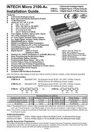
<strong>2100</strong>-<strong>A16</strong> Connection Example Diagram for Digital Inputs.<br />
<strong>2100</strong>-<strong>A16</strong><br />
DI4 58<br />
DI 3 57<br />
DI 2 56<br />
DI 1 55<br />
DI COM 54<br />
24Vdc<br />
4.7k<br />
o/p<br />
Open Collector<br />
Digital Output<br />
5~30Vdc<br />
3 wire proximity transducer,<br />
paddle wheel, etc.<br />
Reed Switch or<br />
Relay contact.<br />
Note 1.<br />
Note 2.<br />
Note 3.<br />
Note 4.<br />
Note 5.<br />
Note 6.<br />
Inputs can be:<br />
State - i.e. ON or OFF.<br />
Count - 0~50Hz<br />
LED indication per input. LED intensity depends<br />
on voltage level at the input terminals. Refer to<br />
‘Specifications’ for input loads.<br />
For scaling of counter inputs, totalising and flow<br />
data conversion, refer to Microscan Configuration<br />
Manual, line setup/counter scaling.<br />
All cables must be screened, with screen earthed<br />
at one end only. Refer ‘The Proper <strong>Installation</strong> &<br />
Wiring of the <strong>2100</strong>-<strong>A16</strong>.’<br />
Do not fit the 4K7 resistor for 3 wire PNP<br />
transducers.<br />
Digital Inputs are not available when used as an<br />
intelligent multiplexer.<br />
<strong>2100</strong>-<strong>A16</strong> Connection Diagram Using an LPI-D Current Loop Isolator on the Input.<br />
<strong>2100</strong>-M<br />
COM 51<br />
Analogue Output<br />
Iout 53<br />
4~20mA loop<br />
24Vdc Regulated<br />
Power Supply.<br />
LPI-D<br />
+ -<br />
+ 4<br />
2 - - 5<br />
4~20mA loop<br />
1 +<br />
2kV Isolation Barrier<br />
Input<br />
Output<br />
1<br />
2<br />
<strong>2100</strong>-<strong>A16</strong><br />
+<br />
Analogue Input<br />
-<br />
<strong>2100</strong>-<strong>A16</strong> Connection Diagram Using an XI-P1 Current Loop Isolator on the Input.<br />
<strong>2100</strong>-M<br />
COM 51<br />
Analogue Output<br />
Iout 53<br />
4~20mA loop<br />
1kV<br />
XI-P1<br />
Input Output<br />
- + - +<br />
4 3 2 1<br />
4~20mA loop<br />
Isolation Barrier<br />
1<br />
2<br />
<strong>2100</strong>-<strong>A16</strong><br />
+<br />
Analogue Input<br />
-<br />
<strong>2100</strong>-<strong>A16</strong> Connection Example Diagram for Digital Outputs.<br />
Audible<br />
Alarm<br />
P/S<br />
12 12 12 COOLING<br />
12 12<br />
12<br />
50<br />
51<br />
52<br />
<strong>2100</strong>-<strong>A16</strong><br />
Relay 1<br />
Relay 2<br />
Note 1.<br />
Note 2.<br />
Note 3.<br />
Note 4.<br />
Note 5.<br />
Note 6.<br />
Note 7.<br />
Both relays are Normally Open, and share a common.<br />
30Vac/dc, 1A maximum contact rating. For individual relay outputs<br />
(ie not sharing a common) and/or a contact rating of 250Vac, use a<br />
<strong>2100</strong>-RL2. This is a 2 relay slave board that can be wired directly to<br />
the <strong>2100</strong>-<strong>A16</strong>.<br />
Each relay can be configured for a ‘Normally ON’ or ‘Normally OFF’<br />
output state. (E.g. for fail safe operation.) The ‘Normally ON/OFF’<br />
settings are retained in software on power down, but the relays are<br />
de-energized. Refer to MicroScan Configuration Manual.<br />
Relay 2 can be selected as a Comms failure time-out alarm. The<br />
relay is normally active and deactivates after 5mins if no Comms<br />
messages are received. This function does not detect<br />
microprocessor failure. When used for this function the relay<br />
cannot be used for any other function.<br />
LED indication on each output when relay is energized.<br />
For additional Relay Expansion refer <strong>2100</strong>-R2.<br />
Digital Outputs are not available when used as an intelligent<br />
multiplexer.<br />
14.02-10