Download 2100-A16 Installation Guide - Intech Instruments Ltd
Download 2100-A16 Installation Guide - Intech Instruments Ltd
Download 2100-A16 Installation Guide - Intech Instruments Ltd

You also want an ePaper? Increase the reach of your titles
YUMPU automatically turns print PDFs into web optimized ePapers that Google loves.
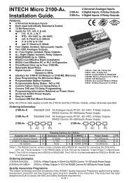
<strong>2100</strong>-<strong>A16</strong> Rev. 1 PLC RTX Fail Safe System<br />
The PLC uses one channel of the <strong>2100</strong>-<strong>A16</strong> to verify that the <strong>A16</strong> is reading the channel correctly, AO1 is working and<br />
the clock and reset/BCD channel select is working.<br />
Test Channel = spare channel on <strong>2100</strong>-<strong>A16</strong>, set to RTD 0-850C. This has a PLC relay connected which is used to short<br />
out A-B, under the PLCs command. Do not use channel 1 as the test channel.<br />
Sequence of operation.<br />
1. The PLC reads the required channels as normal.<br />
2. The PLC then advances to the test channel (the next free channel or channel 16)<br />
3. The test channel is read.<br />
4. The relay changes state to alter the reading of the test channel.<br />
5. 1. to 4. are repeated. If the reading on the test channel does not alternate between 4 mA and 10 mA as the relay<br />
changes state, within the specified tolerances as listed below then there is a fault in the system. The PLC software<br />
should be setup to detect these values as the relay changes state.<br />
Relay<br />
State<br />
Closed<br />
Open<br />
Test<br />
Channel Reading<br />
Less<br />
than -15C<br />
Approx<br />
320 +/-10C<br />
Output<br />
Value<br />
PLC Test Value<br />
4 mA<br />
Test for 5mA and below.<br />
10mA<br />
Test for above 9.5mA and below 10.5mA.<br />
Analog in -<br />
Analog in +<br />
60 AO COM<br />
61 AO 1<br />
PLC<br />
COM<br />
RST Out<br />
CLK Out<br />
54 DI COM<br />
55 DI 1 (RST)<br />
56 DI 2 (CLK)<br />
<strong>2100</strong>-<strong>A16</strong><br />
Test relay<br />
Clean Contacts,<br />
Normally Open<br />
220R<br />
46 A Test Channel.<br />
47 B (Eg.Channel 16)<br />
48 B<br />
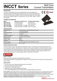
<strong>2100</strong>-<strong>A16</strong> Analogue Signal Converted to Frequency for a PLC, using a TWI-FO.<br />
Description.<br />
The TWI-FO converts 4~20mA from a <strong>2100</strong>-AO to a frequency output. (Typically 10~1010Hz, but this is rangeable.)<br />
A PLC with two digital outputs and one digital input can receive sixteen multiplexed analogue inputs.<br />
Eg. <strong>2100</strong>-<strong>A16</strong><br />
TWI-FO<br />
eg. PLC<br />
49<br />
20V<br />
1<br />
P/S1<br />
4<br />
P/S2<br />
24Vdc<br />
61<br />
O/P 4~20mA<br />
2<br />
I/P<br />
5<br />
F/O<br />
D/I<br />
60<br />
COM.<br />
3<br />
COM1<br />
1600V<br />
6<br />
COM2<br />
Isolation<br />
COM<br />
Section F. Communications.<br />
<strong>2100</strong>-<strong>A16</strong> ‘PLC Message’ Communication Protocol.<br />
‘Read Only From <strong>2100</strong>-<strong>A16</strong>’ and ‘Read and Write to <strong>2100</strong>-<strong>A16</strong>’ Protocols are both available from <strong>Intech</strong> <strong>Instruments</strong> in<br />
‘WORD’ format, free of charge.<br />
Read Message is PLC compatible read DM area. <strong>2100</strong>-<strong>A16</strong> protocol is the protocol used by Microscan to access data<br />
in stations. Both protocols use ASCII, except <strong>2100</strong>-<strong>A16</strong> uses IEEE754 to represent floating point numbers.<br />
<strong>2100</strong>-<strong>A16</strong> ‘Modbus RTU/TCP’ Communication Protocol.<br />
Note 1: This section only applies to an <strong>2100</strong>-<strong>A16</strong> with Modbus RTU Protocol.<br />
Note 2: Can be used on Modbus TCP with a Modbus TCP to RTU Bridge. ie Schneider Electric ‘174 CEV 300 20’.<br />
Note 3: <strong>2100</strong>-ME Memory Board cannot be used when Modbus RTU protocol is used.<br />
Modbus RTU Comms Specifications:<br />
Error Check<br />
Standard Modbus CRC.<br />
End of message framing delay Min 5msec, Max 7.5msec. (Minimum spec is 3.5msec at 9600 baud).<br />
Counting is based on internal 2.5 msec timer.<br />
Product Liability. Due to ongoing research and development, designs, specifications, and documentation are subject to change without notification.<br />
14.02-20