Download 2100-A16 Installation Guide - Intech Instruments Ltd
Download 2100-A16 Installation Guide - Intech Instruments Ltd
Download 2100-A16 Installation Guide - Intech Instruments Ltd

Create successful ePaper yourself
Turn your PDF publications into a flip-book with our unique Google optimized e-Paper software.
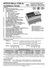
Section C. Input and Output Connection Diagrams.<br />
<strong>2100</strong>-<strong>A16</strong> Input Connection Diagram for mA Inputs.<br />
Connection configuration for 2 wire, 3 wire and 4 wire transmitters, and digital inputs.<br />
Connection Example 1.<br />
24Vdc Regulated<br />
Power<br />
Current Output + Supply. -<br />
Field Transmitters Note 1. All <strong>2100</strong>-<strong>A16</strong> analogue inputs are<br />
2-wire +<br />
<strong>2100</strong>-<strong>A16</strong><br />
Transmitter -<br />
1<br />
+<br />
3-wire<br />
Output<br />
Transmitter<br />
-<br />
Power 4-wire +<br />
Supply Transmitter -<br />
Voltage Free<br />
Contact<br />
1k<br />
2<br />
4<br />
5<br />
7<br />
8<br />
10<br />
11<br />
Connection Example 2.<br />
24Vdc Regulated<br />
Power<br />
Current Output + Supply. -<br />
Field Transmitters<br />
2-wire<br />
Transmitter<br />
+<br />
-<br />
1<br />
+<br />
2<br />
3-wire<br />
Output<br />
4<br />
Transmitter<br />
-<br />
5<br />
Power 4-wire +<br />
7<br />
Supply Transmitter -<br />
8<br />
eg Single Ended Chart<br />
Recorder.<br />
All negative inputs are<br />
connected together.<br />
Channel 1<br />
Channel 2<br />
Channel 3<br />
+ Channel 1<br />
- Common<br />
+ Channel 2<br />
+ Channel 3<br />
+ Channel 1<br />
-<br />
+ Channel 2<br />
-<br />
+ Channel 3<br />
-<br />
+ Channel 4<br />
-<br />
<strong>2100</strong>-<strong>A16</strong><br />
+ Channel 1<br />
-<br />
+ Channel 2<br />
-<br />
+ Channel 3<br />
-<br />
14.02-8<br />
Note 2.<br />
Note 3.<br />
Note 4.<br />
Note 5.<br />
<strong>2100</strong>-<strong>A16</strong> Input Connection Diagram for Millivoltage and Voltage Inputs.<br />
Connection configuration for 3 wire and 4 wire transmitters, and digital inputs.<br />
Power<br />
Supply<br />
Power<br />
Supply<br />
Field<br />
Transmitters<br />
3-wire<br />
Transmitter<br />
3-wire<br />
Transmitter<br />
Voltage Free<br />
Contact<br />
Voltage Free<br />
Contact<br />
+<br />
Output<br />
-<br />
+<br />
Output<br />
-<br />
4-wire<br />
Transmitter<br />
4-wire<br />
Transmitter<br />
+<br />
-<br />
+<br />
-<br />
24Vdc Regulated<br />
Power Supply.<br />
+ -<br />
1k<br />
1k<br />
1<br />
2<br />
4<br />
5<br />
7<br />
8<br />
10<br />
11<br />
<strong>2100</strong>-<strong>A16</strong><br />
+<br />
Channel 1<br />
-<br />
+<br />
-<br />
+<br />
-<br />
Channel 2<br />
Channel 3<br />
+<br />
Channel 4<br />
-<br />
13 +<br />
14 -<br />
16<br />
17<br />
Channel 5<br />
+<br />
Channel 6<br />
-<br />
Note 1.<br />
Note 2.<br />
Note 3.<br />
differential. Exceeding 18V peak between<br />
any 2 inputs, or any single input will cause<br />
errors on ALL channels.<br />
In example 2, the peak voltage is<br />
calculated by multiplying the max mA out<br />
of any transmitter, by the sum of the<br />
resistances in the transmitter loop, then<br />
adding any common peak voltages.<br />
eg: (refer to Connection Example 2)<br />
If the transmitter has a 35mA max, the<br />
<strong>2100</strong>-<strong>A16</strong> has 25 input resistance; and if<br />
a chart recorder has 250 input resistance:<br />
There is a 2V peak common voltage.<br />
=> 35mA x (25 + 250) + 2V = 11.63V peak.<br />
This is fine, as it is less than 18V.<br />
For mA inputs a jumper must be installed.<br />
Failure to install a jumper will cause errors<br />
on ALL channels. J1 for channel 1, J2 for<br />
channel 2, etc. The jumpers are located<br />
directly behind the 3 terminals for each<br />
respective channel. They can be installed<br />
without removing the cover.<br />
Inputs can be used as digital inputs for<br />
sensing a clean, voltage free, field contact.<br />
All cables must be screened, and the<br />
screens earthed at one end only.<br />
Voltage free contact values must be brought<br />
in through ‘tags’ in the Scada Software.<br />
All millivolt and volt inputs are differential.<br />
Exceeding 18V peak between any 2 inputs,<br />
or any single input will cause errors on ALL<br />
channels.<br />
Inputs can be used as digital inputs for<br />
sensing a clean, voltage free, field contact.<br />
All cables must be screened, and the screens<br />
earthed at one end only.<br />
Note 4. Input voltages must not exceed 18V.<br />
Note 5.<br />
Note 6.<br />
For digital inputs the mA jumper must be<br />
installed.<br />
Voltage free contact values must be brought<br />
in through ‘tags’ in the Scada Software.