Download 2100-A16 Installation Guide - Intech Instruments Ltd
Download 2100-A16 Installation Guide - Intech Instruments Ltd
Download 2100-A16 Installation Guide - Intech Instruments Ltd

Create successful ePaper yourself
Turn your PDF publications into a flip-book with our unique Google optimized e-Paper software.
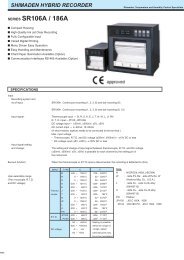
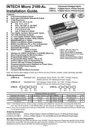
<strong>2100</strong>-<strong>A16</strong> Analogue Outputs Controlled by Scada.<br />
The analogue output mode is set in the Station Advanced Dialog Box ‘AO 1 & AO 2 button’.<br />
For Scada outputs select Mode 2.<br />
For detailed programming info, refer to ‘Programming <strong>2100</strong>-Series Remote Station’ in the Microscan Manual.<br />
AO 1 & AO 2 are controlled by the Scada Software.<br />
12 bit output nominally = 0~4095 for 4~20mA (or 0~10V etc.) out:<br />
0bit = 4mA (0V);<br />
2048 = 12mA (5V);<br />
4095 = 20mA (10V).<br />
<strong>2100</strong>-<strong>A16</strong><br />
AO 2<br />
AO 1<br />
62<br />
61<br />
INDICATOR<br />
INDICATOR<br />
For 4~20mA output, Loop Powered Indicators can<br />
be used. 12V maximum at 20mA (600 at 20mA)<br />
AO COM<br />
60<br />
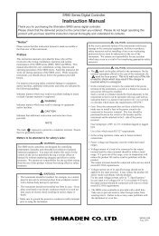
<strong>2100</strong>-<strong>A16</strong> Connection Example Diagram for Using the <strong>2100</strong>-RL2, 2 Relay Slave Board.<br />
<strong>2100</strong>-RL2 Relay Specifications:<br />
<strong>2100</strong>-<strong>A16</strong><br />
<strong>2100</strong>-RL2<br />
NC<br />
-Contact Material Silver Alloy<br />
Relay 2 52<br />
52<br />
-Relay Ratings Rating Approved<br />
Relay 1 COM<br />
Relay 1 51<br />
51<br />
250Vac, 2A UL<br />
COM 50<br />
NO<br />
125Vac, 2A CSA<br />
50<br />
NC<br />
110Vdc, 0.3A;<br />
49<br />
30Vdc, 2A;<br />
Relay 2 COM<br />
48<br />
250Vac,1/6hp;<br />
NO<br />
20Vdc 49<br />
0V 48<br />
125Vac, 1/10hp.<br />
-Number of Operations 2 x 10 5 Min, at 1A, 250Vac<br />
Note 1.<br />
Activating Relay 1 on the <strong>2100</strong>-<strong>A16</strong> activates<br />
Relay 1 on the <strong>2100</strong>-RL2. Activating Relay 2 on<br />
the <strong>2100</strong><strong>A16</strong> activates Relay 2 on the <strong>2100</strong>-RL2.<br />
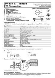
<strong>2100</strong>-<strong>A16</strong> Memory Expansion - Using <strong>2100</strong>-ME Memory Expansion Card.<br />
The <strong>2100</strong>-ME Memory Expansion Card is designed to allow the <strong>2100</strong><strong>A16</strong> to stand alone, retaining the data collected for<br />
intermittent download. Data is held in permanent memory.<br />
<strong>2100</strong>-ME<br />
Connecting the <strong>2100</strong>-<strong>A16</strong> to the <strong>2100</strong>-ME.<br />
1/ Only fit <strong>2100</strong>-ME-32 to <strong>2100</strong>-<strong>A16</strong> Rev.1.3.<br />
2/ Power must be off before installing the <strong>2100</strong>-ME.<br />
3/ Remove the cover off the <strong>2100</strong>-<strong>A16</strong>.<br />
4/ Use antistatic precautions when installing the <strong>2100</strong>-ME.<br />
Carefully orientate the <strong>2100</strong>-ME board as shown above.<br />
Locate the two plastic stand-offs over the corresponding holes<br />
in the <strong>2100</strong>-<strong>A16</strong>, and the 10 pin connector. Once all three are<br />
aligned, push the <strong>2100</strong>-ME firmly into the <strong>2100</strong>-<strong>A16</strong>.<br />
5/ Install a link in position 4 of the <strong>2100</strong>-<strong>A16</strong> S1 Function jumper.<br />
6/ Replace the <strong>2100</strong>-<strong>A16</strong> cover.<br />
7/ When the <strong>2100</strong>-<strong>A16</strong> is used with the <strong>2100</strong>-ME, the <strong>2100</strong>-M<br />
and <strong>2100</strong>-R expansion options are unavailable.<br />
8/ The <strong>2100</strong>-ME can only be fitted to a <strong>2100</strong>-<strong>A16</strong> REV 1.3.<br />
.<br />
CAUTION:<br />
Dangerous Voltages may be present. The <strong>2100</strong>-<strong>A16</strong> has no user serviceable parts.<br />
Protective enclosure only to be opened by qualified personnel.<br />
Remove ALL power sources before removing protective cover.<br />
14.02-12