Download 2100-A16 Installation Guide - Intech Instruments Ltd
Download 2100-A16 Installation Guide - Intech Instruments Ltd
Download 2100-A16 Installation Guide - Intech Instruments Ltd

Create successful ePaper yourself
Turn your PDF publications into a flip-book with our unique Google optimized e-Paper software.
DO NOT GUESS TX OR RX CONNECTIONS. FOLLOW THE TERMINAL NUMBERS IN THE SERIAL CONNECTION DIAGRAMS EXACTLY.<br />
OUTSTATION LAYOUT.<br />
2-Wire RS485 Serial Connections.<br />
COMPUTER PLC<br />
OUTSTATION LAYOUT.<br />
4-Wire RS422 Serial Connections.<br />
COMPUTER PLC<br />
<strong>2100</strong>-NET<br />
10/100 Ethernet to<br />
RS422/485 Converter.<br />
ETHERNET RS232<br />
The <strong>2100</strong>-IS and <strong>2100</strong>-NET are<br />
designed to connect to seperate data<br />
hi-ways and connect to the same<br />
SCADA PC as per the diagram.<br />
74 71 70 Terminal Numbers<br />
COM TX+ TX- Only one converter to be<br />
connected to any one data hiway.<br />
OR<br />
<strong>2100</strong>-IS/NS<br />
RS232 to RS422/485<br />
Converter/Isolator.<br />
74 71 70<br />
COM TX+ TX-<br />
<strong>2100</strong>-NET<br />
10/100 Ethernet to<br />
RS422/485 Converter.<br />
ETHERNET RS232<br />
The <strong>2100</strong>-IS and <strong>2100</strong>-NET are<br />
designed to connect to seperate data<br />
hi-ways and connect to the same<br />
SCADA PC as per the diagram.<br />
74 73 72 71 70 Terminal Numbers<br />
com RX+ RX- TX+ TX- Only one converter to be<br />
connected to any one data hiway.<br />
OR<br />
<strong>2100</strong>-IS/NS<br />
RS232 to RS422/485<br />
Converter/Isolator.<br />
74 73 72 71 70<br />
com RX+ RX- TX+ TX-<br />
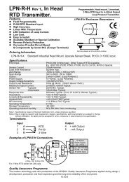
<strong>2100</strong>-<strong>A16</strong><br />
Remote Station.<br />
<strong>2100</strong>-A4<br />
Remote Station.<br />
<strong>2100</strong>-AO<br />
Remote Station.<br />
IMPORTANT:<br />
(i)<br />
70<br />
71<br />
74<br />
<strong>2100</strong>-D<br />
Remote Station.<br />
70<br />
71<br />
74<br />
70<br />
71<br />
74<br />
70<br />
71<br />
74<br />
All cables must be<br />
screened.<br />
(ii) All screens must<br />
be connected<br />
together.<br />
(iii) The screen must<br />
not be earthed at<br />
any point.<br />
RS485 DATA HI-WAY.<br />
CABLE POLARITY<br />
MUST BE OBSERVED<br />
RS485 DATA HI-WAY.<br />
CABLE POLARITY<br />
MUST BE OBSERVED<br />
TWISTED<br />
PAIR<br />
TWISTED<br />
PAIR<br />
To other INTECH MICRO<br />
Remote Stations &<br />
Shimaden Controllers etc.<br />
21<br />
22<br />
1<br />
Shimaden SD20<br />
with RS485 option.<br />
23<br />
22<br />
21<br />
Shimaden SR53/54<br />
with RS485 option.<br />
3<br />
2<br />
1<br />
Shimaden SR73A/74A<br />
with RS485 option.<br />
Resistor = 1k.<br />
Notes:<br />
(i) RS485 can only be used with software release Ver. 4.02 onwards.<br />
(ii) RS485 Data Hi-way is not compatible with RS422 Data Hi-way devices<br />
such as IN-2000-AI, IN-2000-AO, IN-2000-DI, IN-2000-DO, FP21,<br />
SR25, etc. Use a <strong>2100</strong>-4S to interface an RS485 Data Hi-way to an<br />
existing RS422 Data Hi-way<br />
RS232:<strong>2100</strong>-IS convertor is not required to connect the <strong>2100</strong>-232<br />
directly to a PC. Use the RS232 kit to connect the <strong>2100</strong>-232<br />
directly to a PC. The PC requires one RS232 port per <strong>2100</strong>.<br />
RS485: If the outstation is using RS485, it cannot be connected to the same<br />
data hi-way as an outstations using RS422. In the ‘programming’<br />
box, set the ‘TX delay’ box to 20. Set the Dip switches on the<br />
<strong>2100</strong>-IS and the jumpers on the <strong>2100</strong> for RS485 operation.<br />
3<br />
9<br />
5<br />
Shimaden SR253<br />
with RS485 option.<br />
SR82<br />
18<br />
17<br />
SR83<br />
25<br />
24<br />
SR84<br />
22<br />
21<br />
-<br />
+<br />
SG 16 23 1<br />
Shimaden SR80 Series<br />
with RS485 option.<br />
-<br />
+<br />
SR91<br />
12<br />
11<br />
SR92,93,94<br />
3<br />
2<br />
SG 1<br />
1<br />
Shimaden SR90 Series<br />
with RS485 option.<br />
End of Data<br />
Hi-way<br />
Junction Box.<br />
14.02-14<br />
70<br />
71<br />
72<br />
73<br />
74<br />
<strong>2100</strong>-<strong>A16</strong><br />
Remote Station.<br />
70<br />
71<br />
72<br />
73<br />
74<br />
<strong>2100</strong>-A4<br />
Remote Station.<br />
70<br />
71<br />
72<br />
73<br />
74<br />
<strong>2100</strong>-D<br />
Remote Station.<br />
70<br />
71<br />
72<br />
73<br />
74<br />
<strong>2100</strong>-AO<br />
Remote Station.<br />
21<br />
20<br />
23<br />
22<br />
IN-2000-AI<br />
Remote Station.<br />
36<br />
35<br />
38<br />
37<br />
IN-2000-DI<br />
Remote Station.<br />
26<br />
25<br />
28<br />
27<br />
IN-2000-DO<br />
Remote Station.<br />
4<br />
6<br />
3<br />
9<br />
5<br />
Shimaden FP21<br />
with RS422 option<br />
4<br />
6<br />
3<br />
9<br />
5<br />
Shimaden SR25/253<br />
with RS422 option<br />
25<br />
24<br />
23<br />
22<br />
21<br />
Shimaden SR53/54<br />
with RS422 option<br />
5<br />
4<br />
3<br />
2<br />
1<br />
Shimaden SR73A/74A<br />
with RS422 option<br />
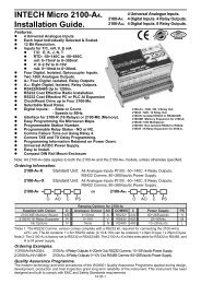
RS422 DATA HI-WAY.<br />
CABLE POLARITY<br />
MUST BE OBSERVED<br />
IMPORTANT:<br />
To other INTECH MICRO Remote (i)<br />
Stations & Shimaden Controllers etc.<br />
End of Data<br />
Hi-way<br />
Junction Box.<br />
TWISTED<br />
PAIR<br />
TWISTED<br />
PAIR<br />
TWISTED<br />
PAIR<br />
TWISTED<br />
PAIR<br />
Resistor = 1k.<br />
RS422 DATA HI-WAY.<br />
CABLE POLARITY<br />
MUST BE OBSERVED<br />
70<br />
71<br />
72<br />
73<br />
74<br />
24<br />
23<br />
21<br />
22<br />
1<br />
70<br />
71<br />
74<br />
<strong>2100</strong>-4S RS422<br />
to RS485 Converter<br />
RS485<br />
Shimaden SD20<br />
with RS422 option<br />
All cables must be<br />
screened.<br />
(ii) All screens must<br />
be connected<br />
together.<br />
(iii) The screen must<br />
not be earthed at<br />
any point.