Installation Guide ECS5510-48S 48-Port 10G Ethernet ... - Edge-Core
Installation Guide ECS5510-48S 48-Port 10G Ethernet ... - Edge-Core
Installation Guide ECS5510-48S 48-Port 10G Ethernet ... - Edge-Core

You also want an ePaper? Increase the reach of your titles
YUMPU automatically turns print PDFs into web optimized ePapers that Google loves.
CHAPTER 1 | Introduction<br />
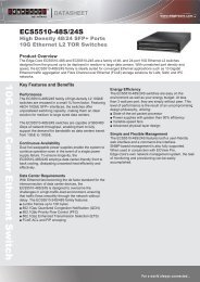
Description of Hardware<br />
PORT AND SYSTEM STATUS LEDS<br />
The switch includes a display panel for key system and port indications that<br />
simplify installation and network troubleshooting. The LEDs, which are located<br />
on the front panel for easy viewing, are shown below and described in the<br />
following tables.<br />
Figure 7: Status LEDs<br />
System Status LEDs<br />
SFP+ <strong>Port</strong> Status LEDs<br />
Management <strong>Port</strong><br />
Status LED<br />
Table 1: <strong>10G</strong> SFP+ <strong>Port</strong> Status LEDs (1~<strong>48</strong>)<br />
LED Condition Status<br />
Link/Activity On/Flashing Green <strong>Port</strong> has established a valid network connection.<br />
Flashing indicates activity.<br />
Off<br />
There is no valid link on the port.<br />
Table 2: 1000 Mbps RJ-45 Management <strong>Port</strong> Status LED<br />
LED Condition Status<br />
Link/Activity On/Flashing Green <strong>Port</strong> has established a valid network connection.<br />
Flashing indicates activity.<br />
Off<br />
There is no valid link on the port.<br />
– 31 –