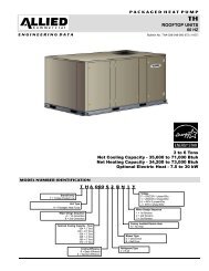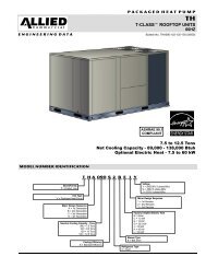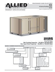
K-Series (7.5-12.5 KGA) Installation Instructions - Allied Commercial
K-Series (7.5-12.5 KGA) Installation Instructions - Allied Commercial
K-Series (7.5-12.5 KGA) Installation Instructions - Allied Commercial

You also want an ePaper? Increase the reach of your titles
YUMPU automatically turns print PDFs into web optimized ePapers that Google loves.
2− Combustion air pressure switch proves inducer MSAV TM Start−Upoperation. After a 30−second pre−purge, power isallowed to ignition control. Switch is factory set andA−Generalrequires no adjustment.Optional Multi−Stage Air Volume (MSAV TM ) units are3− Spark ignitor energizes and gas valve solenoid opens.available which provide two blower speeds. The blowerwill operate at lower speeds when cooling demand is low4− Spark ignites gas, ignition sensor proves the flameand higher speeds when cooling demand is high. Thisand combustion continues.results in lower energy consumption.5− If flame is not detected after first ignition trial, ignition MSAV TM units will operate at high speed duringcontrol will repeat steps 3 and 4 two more times ventilation (blower G" only signal) but can be adjusted tobefore locking out the gas valve.operate at low speed.6− For troubleshooting purposes, an ignition attempt Low speed is approximately 2/3 of the full speed RPM.after lock out may be re−established manually. MoveB−Set Maximum Blower CFMthermostat to OFF" and return thermostat switch toHEAT" position.1− Initiate a blower (G) only signal from the roomthermostat or control system.B−Ignition Control Diagnostic LED’s2− Adjust the blower pulley to deliver the full (highTABLE 9speed) CFM in the typical manner. See DeterminingIGNITION CONTROL HEARTBEAT LED STATUSUnit CFM in the Blower Operation and AdjustmentLEDIndicatessection.FlashesC−Set Blower Speed During VentilationSlow Normal operation. No call for heat.To save energy during ventilation, the blower speed canFast Normal operation. Call for heat.be set to low. This is accomplished by changing theSteady OffInternal control fault OR no power toventilation speed switch on the VFD control board to LO".control OR Gas Valve Relay Fault.See figure 19.Steady On Control internal failure.Note − On units equipped with an economizer, set damperminimum position as shown in the next section. After2 Lockout. Failed to detect or sustain flame.adjusting the low speed minimum position, the ventilationProve switch open or closed or rollout3speed switch will be in the LO" position.switch open.D−Set Damper Minimum Position (Units W/ Economizer)Limit switch is open and/or limit has4opened three times.To maintain required minimum ventilation air volumes5when the unit is in the occupied mode, two minimumFlame sensed but gas valve solenoidnot energized.damper positions must be set. A high and a low speedC−Limit Controlspotentiometer are provided on the VFD control board toadjust minimum damper position. See figure 19.Limit controls are factory−set and are not adjustable. TheSet High Speed Minimum Positionprimary limit is located on the blower deck to the right of1− Initiate a blower (G) only AND occupied demand fromblower assembly.the room thermostat or control system.D−Heating AdjustmentMain burners are factory−set and do not requireadjustment.The following manifold pressures are listed on the gas valve.Natural Gas Units − Low Fire − 1.6" w.c. (not adjustable)Natural Gas Units − High Fire − 3.7" w.c.LP Gas Units − Low Fire − 5.5" w.c. (not adjustable)LP Gas Units − High Fire − 10.5" w.c.2− Set the ventilation speed switch on the VFD controlboard to HI".3− Rotate the high speed potentiometer on the VFDcontrol board to set the high speed minimum damperposition.4− Measure the intake air CFM. If the CFM is lower thanthe design specified CFM for ventilation air, use thepotentiometer to increase the damper percent open.If the CFM is higher than specified, decrease theElectric Heat Start−Up (KCA Units)damper percent open.Optional electric heat will stage on and cycle withthermostat demand. Number of stages of electric heat willvary depending on electric heat assembly. See electricheat wiring diagram on unit for sequence of operation.Note − Intake air CFM can also be determined using theoutdoor air temperature, return air temperature andmixed air temperature. Refer to the economizer oroutdoor air damper installation instructions.Page 20