K-Series (7.5-12.5 KGA) Installation Instructions - Allied Commercial
K-Series (7.5-12.5 KGA) Installation Instructions - Allied Commercial
K-Series (7.5-12.5 KGA) Installation Instructions - Allied Commercial

You also want an ePaper? Increase the reach of your titles
YUMPU automatically turns print PDFs into web optimized ePapers that Google loves.
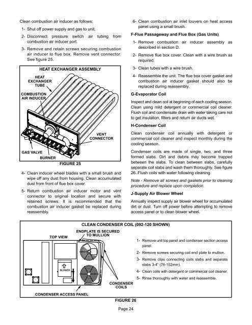
Clean combustion air inducer as follows:1− Shut off power supply and gas to unit.2− Disconnect pressure switch air tubing fromcombustion air inducer port.3− Remove and retain screws securing combustionair inducer to flue box. Remove vent connector.See figure 25.COMBUSTIONAIR INDUCERHEAT EXCHANGER ASSEMBLYHEATEXCHANGERTUBE6− Clean combustion air inlet louvers on heat accesspanel using a small brush.F−Flue Passageway and Flue Box (Gas Units)1− Remove combustion air inducer assembly asdescribed in section D.2− Remove flue box cover. Clean with a wire brush asrequired.3− Clean tubes with a wire brush.4− Reassemble the unit. The flue box cover gasket andcombustion air inducer gasket should also bereplaced during reassembly.G−Evaporator CoilInspect and clean coil at beginning of each cooling season.Clean using mild detergent or commercial coil cleaner.Flush coil and condensate drain with water taking care notto get insulation, filters and return air ducts wet.H−Condenser CoilGAS VALVEBURNERFIGURE 25VENTCONNECTOR4− Clean inducer wheel blades with a small brush andwipe off any dust from housing. Clean accumulateddust from front of flue box cover.5− Return combustion air inducer motor and ventconnector to original location and secure withretained screws. It is recommended that thecombustion air inducer gasket be replaced duringreassembly.Clean condenser coil annually with detergent orcommercial coil cleaner and inspect monthly during thecooling season.Condenser coils are made of single, two, and threeformed slabs. Dirt and debris may become trappedbetween the slabs. To clean between slabs, carefullyseparate coil slabs and wash them thoroughly. See figure26. Flush coils with water following cleaning.Note − Remove all screws and gaskets prior to cleaningprocedure and replace upon completion.J−Supply Air Blower WheelAnnually inspect supply air blower wheel for accumulateddirt or dust. Turn off power before attempting to removeaccess panel or to clean blower wheel.CLEAN CONDENSER COIL (092−120 SHOWN)TOP VIEWBLOWERENDPLATE IS SECUREDTO MULLIONCONDENSERCOILS1− Remove unit top panel and condenser section accesspanel.2− Remove screws securing coil end plate to mullion.3− Remove clips connecting coils slabs and separateslabs 3−4" (76−102mm).4− Clean coils with detergent or commercial coil cleaner.5− Rinse thoroughly with water and reassemble.CONDENSER ACCESS PANELFIGURE 26Page 24