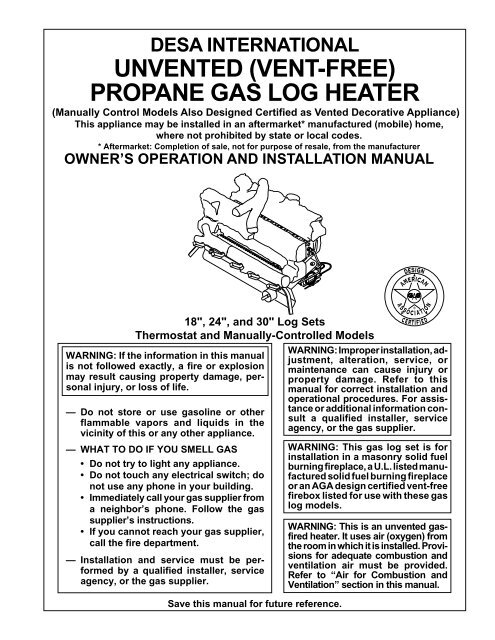
desa international unvented (vent-free) propane gas log heater
desa international unvented (vent-free) propane gas log heater
desa international unvented (vent-free) propane gas log heater
- No tags were found...

Create successful ePaper yourself
Turn your PDF publications into a flip-book with our unique Google optimized e-Paper software.
AIR FORCOMBUSTIONANDVENTILATIONContinuedWARNING ICON G 001WARNINGIf the area in which the <strong>heater</strong> may be operated is smaller thanthat defined as an unconfined space, provide adequate combustionand <strong>vent</strong>ilation air by one of the methods described in theNational Fuel Gas Code, ANSI Z223.1, 1992, Section 5.3.VENTILATION AIRVentilation Air From Inside BuildingThis fresh air would come from an adjoining unconfined space. When <strong>vent</strong>ilating to anadjoining unconfined space, you must provide two permanent openings: one within 12" of theceiling and one within 12" of the floor on the wall connecting the two spaces (see options 1 and2, Figure 2). You can also remove door into adjoining room (see option 3, Figure 2). Followthe National Fuel Gas Code NFPA 54/ANSI Z223.1, Section 5.3, Air for Combustion andVentilation for required size of <strong>vent</strong>ilation grills or ducts.WARNING ICON G 001WARNINGRework worksheet, adding the space of the adjoining unconfinedspace. The combined spaces must have enough fresh air to supply allappliances in both spaces.12"VentilationGrillsInto AdjoiningRoom,Option 1OrRemoveDoor intoAdjoiningRoom,Option3Ventilation GrillsInto Adjoining Room,Option 212"Figure 2 - Ventilation Air from Inside BuildingVentilation Air From OutdoorsProvide extra fresh air by using <strong>vent</strong>ilation grills or ducts. You must provide two permanentopenings: one within 12" of the ceiling and one within 12" of the floor. Connect theseitems directly to the outdoors or spaces open to the outdoors. These spaces include atticsand crawl spaces.IMPORTANT: Do not provide openings for inlet or outlet air into attic if attic has a thermostat-controlledpower <strong>vent</strong>. Heated air entering the attic will activate the power <strong>vent</strong>.OutletAirVentilatedAtticOutletAirTo AtticInletAirInlet AirVentilatedCrawl SpaceToCrawlSpace101309Figure 3 - Ventilation Air from Outdoors7
INSTALLINGNOTICEA qualified service person must install <strong>heater</strong>. Follow all local codes.NOTICEState or local codes may only allow operation of this appliance in a<strong>vent</strong>ed configuration. Check your state or local codes.WARNING ICON G 001WARNINGBefore installing in a solid fuel burning fireplace, the chimney flueand firebox must be cleaned of soot, creosote, ashes and loose paintby a qualified chimney cleaner. Creosote will ignite if highly heated.Inspect chimney flue for damage. If damaged, operate <strong>heater</strong> withflue damper closed.WARNING ICON G 001WARNINGSeal any fresh air <strong>vent</strong>s or ash clean-out doors located on floor or wallof fireplace. If not, drafting may cause pilot outage or sooting. Use aheat-resistant sealant. Do not seal chimney flue damper.WARNING ICON G 001WARNINGNever install the <strong>heater</strong>• in a bedroom or bathroom• in a recreational vehicle• where curtains, furniture, clothing, or other flammable objects areless than 36 inches from the front, top, or sides of the <strong>heater</strong>• in high traffic areas• in windy or drafty areasWARNING ICON G 001CAUTIONThis <strong>heater</strong> creates warm air currents. These currents move heatto wall surfaces next to <strong>heater</strong>. Installing <strong>heater</strong> next to vinyl orcloth wall coverings or operating <strong>heater</strong> where impurities in the air(such as tobacco smoke) exist, may discolor walls.IMPORTANT: Vent-<strong>free</strong> <strong>heater</strong>s add moisture to the air. Although this is beneficial,installing <strong>heater</strong> in rooms without enough <strong>vent</strong>ilation air may cause mildew to formfrom too much moisture. See Air for Combustion and Ventilation, pages 5 through 8.CHECK GAS TYPEUse only <strong>propane</strong> <strong>gas</strong>. If your <strong>gas</strong> supply is not <strong>propane</strong>, do not install <strong>heater</strong>. Calldealer where you bought <strong>heater</strong> for proper type <strong>heater</strong>.8101309
INSTALLINGContinuedINSTALLATION AND CLEARANCES (Vent-Free Operation Only)WARNINGMaintain the minimum clearances. If you can, provide greater clearancesfrom floor, ceiling, and adjoining wall.MINIMUM FIREPLACE CLEARANCETO COMBUSTIBLE MATERIALSLog Size Side Wall Ceiling Floor18", 24", 30" 16" 42" 5"LOG SIZING REQUIREMENTSLog Minimum Firebox SizeSize Height Depth Front Width Rear Width18" 17" 14" 20" 14"24" 17" 14" 26" 18"30" 17" 14" 32" 22"Carefully follow the instructions below. This will ensure safe installation into amasonry or U.L. listed manufactured fireplace.Minimum Wall and Ceiling Clearances (see Figure 4)A. Clearances from the side of the fireplace opening to any combustible wallshould not be less than 16 inches.B. Clearances from the top of the fireplace opening to the ceiling should not beless than 42 inches.42"16"Figure 4 - Minimum Clearance to Wall and Ceiling101309Continued9
INSTALLINGContinuedNOTICEManual control <strong>heater</strong>s may be used as a <strong>vent</strong>edproduct. If so, you must always run <strong>heater</strong> withchimney flue damper open. If running <strong>heater</strong> withdamper open, non-combustible material abovefireplace opening is not needed. Go to InstallingDamper Clamp Accessory for Vented Operation,page 13.Minimum Non Combustible Material ClearancesIf Not Using MantelNote: If using a mantel, go to page 11. If not using a mantel, follow the informationon this page.You must have non combustible material(s) above the fireplace opening. Noncombustible materials (such as slate, marble, tile, etc.) must be at least 1/2 inchthick. With sheet metal, you must have non combustible material behind it. Noncombustible material must extend at least 8" up (for all models). If non combustiblematerial is less than 12", you must install the fireplace hood accessory (24" and 30"models only). See chart below and Figure 5 for minimum clearances.IMPORTANT: If you cannot meet these minimum clearances, you must operate<strong>heater</strong> with chimney flue damper open. Go to Installing Damper Clamp Accessoryfor Vented Operation, page 13.Non-Combustible Requirements forMaterial Distance (A) Safe Installation12" or more Non combustible material OK.Between 8" and 12" 24" or 30" Models: Install fireplace hoodacessory (GA6050 or GA6052, seeAccessories, page 33).18" Model: Non combustible material OK.Less than 8"Non combustible material must beextended to at least 8". See Between 8"and 12", above. If you cannot extendmaterial, you must operate <strong>heater</strong> withflue damper open.Heat ResistantMaterial(A)10Figure 5 - Heat Resistant Material (Slate, Marble, Tile, etc.) Above Fireplace101309
INSTALLINGContinuedMinimum Non Combustible Material ClearancesIf Using MantelYou must have non combustible material(s) above the fireplace opening. Noncombustible materials (such as slate, marble, tile, etc.) must be at least 1/2 inchthick. With sheet metal, you must have non combustible material behind it. Noncombustible material must extend at least 8 inches up (for all models). If noncombustible material is less than 12", you must install the fireplace hood accessory(24" and 30" models only). Even if non combustible material is more than 12", youmay need the hood accessory to deflect heat away from your mantel shelf. Seechart below and Figures 6 and 7 for minimum clearances.IMPORTANT: If you cannot meet these minimum clearances, you must operate<strong>heater</strong> with chimney flue damper open. Go to Installing Damper Clamp Accessoryfor Vented Operation, page 13.Non Combustible Requirements forMaterial Distance (A) Safe Installation12" or more Non combustible material OK.Between 8" and 12" 24" or 30" Models: Install fireplace hoodacessory (GA6050 or GA6052, seeAccessories, page 33).18" Model: Non combustible material OK.Less than 8"Non combustible material must beextended to at least 8". See Between 8"and 12", above. If you cannot extendmaterial, you must operate <strong>heater</strong> withflue damper open.Mantel ClearancesIf you meet minimum clearance between mantel shelf and top of fireplace opening,a hood is not required (see Figure 6).Mantel Shelf10"8"6"2 1 /2"Underside ofMantel ShelfAll minimumdistances arein inchesMinimum Non-CombustibleMaterial(A)12"20"24 1 /2"27 1 /2"30"Log Set24"/30" Models8"14"16 3 /4"18 1 /2"20"18" ModelMinimum Non-CombustibleMaterial HeightDistances toUnderside ofMantelTop of FireplaceOpening101309Figure 6 - Minimum Mantel Clearances Without Using HoodIf above minimum clearances are not met, you must have a hood. Followminimum clearances shown in Figure 7 when using hood. Continued11
INSTALLINGContinued12"10"8"Mantel ShelfUnderside ofMantel Shelf6"Minimum Non-CombustibleMaterial2 1 /2"8"Min.12" 15" 18"20"All minimumdistances arein inchesLog Sets18", 24",& 30" ModelsHood(GA6050, GA6052)Distances toUnderside ofMantelTop of FireplaceOpeningFigure 7 - Minimum Mantel Clearances When Using HoodIf your installation does not meet the above minimum clearances, you must:• operate the <strong>log</strong>s only with the flue damper open, OR• raise the mantel to an acceptable height, OR• remove the mantel.Floor ClearancesA. If installing appliance on the floor level, you must maintain the minimumdistance of 14" to combustibles (see Figure 8).14"Min.CombustibleMaterialNon-CombustibleMaterialFigure 8 - Minimum Fireplace Clearances If Installed at Floor LevelB. If combustible materials are less than 14" to the fireplace, you must installappliance at least 5" above the combustible flooring (see Figure 9).Hearth5"Min.CombustibleMaterial12Figure 9 - Minimum Fireplace Clearances Above Combustible Flooring101309
INSTALLINGContinuedINSTALLING DAMPER CLAMP ACCESSORY FORVENTED OPERATIONNote: When used as a <strong>vent</strong>ed <strong>heater</strong>, appliance must be installed only in a solidfuelburning fireplace with a working flue and constructed of non combustiblematerial.If your <strong>heater</strong> is a manually controlled model, you may use this <strong>heater</strong> as a <strong>vent</strong>edproduct. There are three reasons for operating your <strong>heater</strong> in the <strong>vent</strong>ed mode.1. The fireplace does not meet the clearance to combustibles requirements for<strong>vent</strong>-<strong>free</strong> operation.2. State or local codes do not permit <strong>vent</strong>-<strong>free</strong> operation.3. You prefer <strong>vent</strong>ed operation.If reasons number 1 or 2 above apply to you, you must permanently open chimney fluedamper. You must install the damper clamp accessory (to order, see Accessories, page33). This will insure <strong>vent</strong>ed operation (see Figure 10). The damper clamp will keepdamper open. Installation instructions are included with clamp accessory.See chart below for minimum permanent flue opening you must provide. Attachdamper clamp so the minimum permanent flue opening will be maintained at all times.Chimney Minimum PermanentHeight (ft.) Flue Opening (sq. ins.)6' to 15' 39 sq. inches15' to 30' 29 sq. inchesArea of Various Standard Round FluesDiameter (ins.) Area (sq. ins.)5" 20 sq. inches6" 29 sq. inches7" 39 sq. inches8" 51 sq. inchesDamperClampDamperDamperClampDamperDamper101309Masonry FireplaceFigure 10 - Attaching Damper ClampManufactured Fireplace13
INSTALLINGContinuedINSTALLING HEATER BASE ASSEMBLYWARNING ICON G 001WARNINGYou must secure this <strong>heater</strong> to fireplace floor. If not, <strong>heater</strong> will movewhen you adjust controls. Moving <strong>heater</strong> may cause a <strong>gas</strong> leak.WARNING ICON G 001WARNINGIf installing in a sunken fireplace, special care is needed. Youmust raise the fireplace floor to allow access to <strong>heater</strong> controlpanel. This will insure adequate air flow and guard against sooting.Raise fireplace floor with non-combustible material. Makesure material is secure.WARNING ICON G 001CAUTIONDo not pick up <strong>heater</strong> base assembly by burners. This coulddamage <strong>heater</strong>. Only handle base assembly by grates.IMPORTANT: Make sure the <strong>heater</strong> burners are level. If <strong>heater</strong> is not level, <strong>heater</strong> willnot work properly. For thermostat models, avoid damage to thermostat bulb. Avoidnicks or sharp bends in thermostat bulb wire. Keep thermostat bulb in mountingbracket.Installation Items Needed• hardware package (provided with <strong>heater</strong>)• approved flexible <strong>gas</strong> hose (not provided) (if allowed by local codes)• sealant (resistant to LP <strong>gas</strong>, not provided)• electric drill with 3/16" drill bit1. Apply pipe joint sealant lightly to male threads of <strong>gas</strong> regulator. Connect approvedflexible <strong>gas</strong> hose to <strong>gas</strong> regulator of <strong>heater</strong> (see Figure 11).IMPORTANT: Hold <strong>gas</strong> regulator with wrench when connecting flexible <strong>gas</strong> hose.2. Locate mounting brackets, bolts, and nuts in hardware package. Attach mountingbrackets to <strong>heater</strong> base (see Figure 12). Attach nuts finger tight.3. Position <strong>heater</strong> base assembly in fireplace.4. Mark screw locations through holes in mounting brackets. If installing in a brickbottomfireplace, mark screw locations in mortar joint of bricks.5. Remove <strong>heater</strong> base from fireplace. Remove mounting brackets from <strong>heater</strong> base.6. Drill holes at marked locations using 3/16" drill bit.7. Attach mounting brackets to fireplace floor using masonry screws (in hardware package).8. Reattach <strong>heater</strong> base to mounting brackets. Tighten nuts firmly.9. Connect to <strong>gas</strong> supply. See Connecting To Gas Supply, page 15.Heater GasRegulatorFlexible Gas Hose (ifallowed by local codes)Figure 11 - Attaching Flexible Gas Hose to Heater Gas Regulator14101309
INSTALLINGContinuedMasonry ScrewMountingBracketFigure 12 - Attaching Mounting Brackets to HeaterCONNECTING TO GAS SUPPLYNOTICEA qualified service person must connect <strong>heater</strong> to <strong>gas</strong> supply.Follow all local codes.WARNING ICON G 001CAUTIONNever connect <strong>heater</strong> directly to the <strong>propane</strong> supply. This <strong>heater</strong>requires an external regulator (not supplied). Install the externalregulator between the <strong>heater</strong> and <strong>propane</strong> supply.Installation Items NeededBefore installing <strong>heater</strong>, make sure you have the items listed below.• external regulator (supplied byinstaller, see page 16)• piping (check local codes)• sealant (resistant to LP <strong>gas</strong>)• manual shutoff valve *• test gauge connection *• sediment trap• tee joint• pipe wrench* An A.G.A. design-certified manual shutoff valve with 1/8" NPT tap is an acceptablealternative to test gauge connection. Purchase the optional A.G.A. design-certified manualshutoff valve from your dealer. See Accessories, page 33.Continued10130915
INSTALLINGContinuedThe installer must supply an external regulator. The external regulator will reduceincoming <strong>gas</strong> pressure. You must reduce incoming <strong>gas</strong> pressure to between 11 and14 inches of water. If you do not reduce incoming <strong>gas</strong> pressure, <strong>heater</strong> regulatordamage could occur. Install external regulator with the <strong>vent</strong> pointing down asshown in Figure 13. Pointing the <strong>vent</strong> down protects it from <strong>free</strong>zing rain or sleet.PropaneSupply TankExternalRegulatorVent PointingDownFigure 13 - External Regulator With Vent Pointing DownWARNING ICON G 001WARNINGNever connect <strong>heater</strong> to private (non-utility) <strong>gas</strong> wells. This <strong>gas</strong> iscommonly known as well-head <strong>gas</strong>.WARNING ICON G 001CAUTIONUse only new, black iron or steel pipe. Internally-tinned coppertubing may be used in certain areas. Check your local codes. Usepipe of 1/2" diameter or greater to allow proper <strong>gas</strong> volume to<strong>heater</strong>. If pipe is too small, undue loss of pressure will occur.Installation must include a manual shutoff valve, union, and plugged 1/8" NPT tap.Locate NPT tap within reach for test gauge hook up. NPT tap must be upstreamfrom <strong>heater</strong> (see Figure 14, page 17).Apply pipe joint sealant lightly to male threads. This will pre<strong>vent</strong> excess sealantfrom going into pipe. Excess sealant in pipe could result in c<strong>log</strong>ged <strong>heater</strong> valves.WARNING ICON G 001CAUTIONUse pipe joint sealant that is resistant to liquid petroleum (LP) <strong>gas</strong>.Install sediment trap in supply line as shown in Figure 14, page 17. Locate sedimenttrap where it is within reach for cleaning. Locate sediment trap where trappedmatter is not likely to <strong>free</strong>ze. A sediment trap traps moisture and contaminants. Thiskeeps them from going into <strong>heater</strong> controls. If sediment trap is not installed or isinstalled wrong, <strong>heater</strong> may not run properly.16101309
INSTALLINGContinuedWARNING ICON G 001CAUTIONAvoid damage to regulator. Hold <strong>gas</strong> regulator with wrench whenconnecting it to <strong>gas</strong> piping and/or fittings.FromExternal Regulator(11" W.C.** to14" W.C.Pressure)A.G.A. Design-CertifiedManual Shutoff ValveWith 1/8" NPT Tap*Approved FlexibleGas Hose (if allowedby local codes)GasRegulatorTee JointPipeNippleCap3" MinimumSedimentTrapFigure 14 - Gas Connection* Purchase the optional A.G.A. design-certified manual shutoff valve from your dealer.See Accessories, page 33.** Minimum inlet pressure for purpose of input adjustment.CHECKING GAS CONNECTIONSWARNING ICON G 001WARNINGTest all <strong>gas</strong> piping and connections for leaks after installing orservicing. Correct all leaks at once.WARNING ICON G 001WARNINGNever use an open flame to check for a leak. Apply a mixture ofliquid soap and water to all joints. Bubbles forming show a leak.Correct all leaks at once.WARNING ICON G 001CAUTIONMake sure external regulator has been installed between <strong>propane</strong>supply and <strong>heater</strong>. See guidelines under Connecting to Gas Supply,page 15.101309Pressure Testing <strong>gas</strong> Supply Piping systemTest Pressures In Excess Of 1/2 PSIG1. Disconnect <strong>heater</strong> and its individual manual shutoff valve from <strong>gas</strong> supplypiping system. Pressures in excess of 1/2 psig will damage <strong>heater</strong> regulator.2. Cap off open end of <strong>gas</strong> pipe where manual shutoff valve was connected.Continued17
INSTALLINGContinued3. Pressurize supply piping system by either using compressed air oropening <strong>propane</strong> supply tank valve.4. Check all joints of <strong>gas</strong> supply piping system. Apply mixture of liquid soap and water to<strong>gas</strong> joints. Bubbles forming show a leak.5. Correct all leaks at once.6. Re-connect <strong>heater</strong> and manual shutoff valve to <strong>gas</strong> supply. Check re-connected fittingsfor leaks.Test Pressures Equal To or Less Than 1/2 PSIG1. Close manual shutoff valve (see Figure 15).2. Pressurize supply piping system by either using compressed air or opening <strong>propane</strong>supply tank valve.3. Check all joints from <strong>propane</strong> supply tank to manual shutoff valve (see Figure 16).Apply mixture of liquid soap and water to <strong>gas</strong> joints. Bubbles forming show a leak.4. Correct all leaks at once.Pressure Testing Heater Gas Connections1. Open manual shutoff valve (see Figure 15).2. Open <strong>propane</strong> supply tank valve.3. Make sure control knob of <strong>heater</strong> is in the OFF position.4. Check all joints from manual shutoff valve to thermostat <strong>gas</strong> valve (thermostat-controlledmodels) or control valve (manually-controlled models) (see Figure 16). Applymixture of liquid soap and water to <strong>gas</strong> joints. Bubbles forming show a leak.5. Correct all leaks at once.6. Light <strong>heater</strong> (see Operating Heater, pages 20 through 23). Check all other internaljoints for leaks.7. Turn off <strong>heater</strong> (see To Turn Off Gas to Appliance, page 21 [thermostatcontrolledmodels] or page 23 [manually-controlled models]).OpenONPOSITIONManualShutoffValveOFFPOSITIONClosedFigure 15 - Manual Shutoff ValvePropaneSupply TankManualShutoffValveThermostat Gas Valve orControl Valve LocationFigure 16 - Checking Gas Joints18101309
INSTALLINGContinuedINSTALLING LOGSWARNING ICON G 001WARNINGFailure to position the parts in accordance with these diagrams orfailure to use only parts specifically approved with this <strong>heater</strong> mayresult in property damage or personal injury.Each <strong>log</strong> is marked with a number. These numbers will help you identify the <strong>log</strong> wheninstalling. It is very important to install these <strong>log</strong>s exactly as instructed. Do not modify <strong>log</strong>s.Only use <strong>log</strong>s supplied with <strong>heater</strong>.1. Slide rear <strong>log</strong> (#1) into place behind rear burner (see Figure 17).2. Slide front <strong>log</strong> (#2) into place behind front burner. Make sure tabs at bottom of <strong>log</strong> arebehind front burner (see Figure 18).3. Place crossover <strong>log</strong> (#3) into place (see Figure 19). Be sure to place back of crossover<strong>log</strong> into notch on left side of rear <strong>log</strong>. The indentation under front right fork of crossover<strong>log</strong> must rest on rectangular knob of front <strong>log</strong>.4. Place left front branch (#4) and right front branch (#5) (24" and 30" models) or front branch(#4) (18" model) into place (see Figure 20). Make sure notches on bottom rest on grates.5. Add lava rock around base of <strong>heater</strong>.Rear Log(#1)Front Log(#2)TabFigure 18 - Installing Front LogFigure 17 - Installing Rear LogCrossoverLog (#3)NotchesLeft Front Branch (#4)(24" & 30" models)or Front Branch (#4)(18" Model)Right FrontBranch (#5)Notches101309Figure 19 - Installing Crossover LogFigure 20 - Installing Left FrontBranch and Right Front Branch19
OPERATINGHEATERThermostat-Controlled ModelsFOR YOUR SAFETY READ BEFORE LIGHTINGWARNING ICON G 001WARNINGIf you do not follow these instructions exactly, a fire or explosionmay result causing property damage, personal injury or loss of life.A. This appliance has a pilot which must be lighted by hand. When lighting the pilot,follow these instructions exactly.B. BEFORE LIGHTING smell all around the appliance area for <strong>gas</strong>. Be sure to smellnext to the floor because some <strong>gas</strong> is heavier than air and will settle on the floor.WHAT TO DO IF YOU SMELL GAS• Do not try to light any appliance.• Do not touch any electric switch; do not use any phone in your building.• Immediately call your <strong>gas</strong> supplier from a neighbor’s phone. Follow the <strong>gas</strong>supplier’s instructions.• If you cannot reach your <strong>gas</strong> supplier, call the fire department.C. Use only your hand to push in or turn the <strong>gas</strong> control knob. Never use tools. If the knobwill not push in or turn by hand, don’t try to repair it, call a qualified servicetechnician or <strong>gas</strong> supplier. Force or attempted repair may result in a fire or explosion.D. Do not use this appliance if any part has been under water. Immediately call aqualified service technician to inspect the appliance and to replace any part of thecontrol system and any <strong>gas</strong> control which has been under water.LIGHTING INSTRUCTIONSWARNINGWARNING ICON G 001• If fireplace has glass doors, never operate this <strong>heater</strong> with glass doorsclosed. If you operate <strong>heater</strong> with doors closed, heat buildup insidefireplace will cause glass to burst. Also if fireplace opening has <strong>vent</strong>s at thebottom, you must open the <strong>vent</strong>s before operating <strong>heater</strong>.• You must operate this <strong>heater</strong> with a fireplace screen in place. Make surefireplace screen is closed before running <strong>heater</strong>.NOTICEDuring initial operation of new <strong>heater</strong>, burning <strong>log</strong>s will give off a paperburningsmell. Orange flame will also be present. Open damper or windowto <strong>vent</strong> smell. This will only last a few hours.Note: Homeowners generally prefer to operate their <strong>heater</strong> with the chimney damperclosed. This will put all the heat into the room. However there may be times you willdesire the full flames of the Hi heat setting but will find the heat output excessive. Youcan open the chimney damper (if you have one) fully or partially to release some of theheat. WARNING: Damper handle will be hot if <strong>heater</strong> has been running.1. STOP! Read the safety information above.2. Make sure manual shutoff valve is fully open.3. Turn control knob clockwise Clockwise to the OFF position.Ignitor ButtonControl KnobFigure 21 - Control Knob and Ignitor Button Location204. Wait five (5) minutes to clear out any <strong>gas</strong>. Then smell for <strong>gas</strong>, including near thefloor. If you smell <strong>gas</strong>, STOP! Follow “B” in the safety information above. If youdon’t smell <strong>gas</strong>, go to the next step.101309
OPERATINGHEATERThermostat-Controlled ModelsContinuedC-clockwise5. Turn control knob counterclockwise to the PILOT position. Press incontrol knob for five (5) seconds (see Page 20).Note: You may be running this <strong>heater</strong> for the first time after hooking up to <strong>gas</strong>supply. If so, the control knob may need to be pressed in for 30 seconds or less.This will allow air to bleed from the <strong>gas</strong> system.• If control knob does not pop out when released, contact a qualified serviceperson or <strong>gas</strong> supplier for repairs.6. With control knob pressed in, press and release ignitor button. This will light pilot.The pilot is attached to the front burner. If needed, keep pressing ignitor buttonuntil pilot lights.Note: If pilot does not stay lit, contact a qualified service person or <strong>gas</strong> supplierfor repairs. Until repairs are made, light pilot with match. To light pilot withmatch, see Manual Lighting Procedure, below.7. Keep control knob pressed in for 30 seconds after lighting pilot. After 30 seconds,release control knob.Note: If pilot goes out, repeat steps 3 through 7. This <strong>heater</strong> has a safety interlocksystem. Wait one (1) minute for system to reset before lighting pilot again.ThermocoupleIgnitor ElectrodePilot BurnerFigure 22 - Pilot8. Turn control knob counterclockwise C-clockwise to desired heating level. The burnersshould light. Set control knob to any heat level between HI and LO.WARNING ICON G 001CAUTIONDo not try to adjust heating levels by using the manual shutoff valve.TO TURN OFF GAS TO APPLIANCEShutting Off Heater1. Turn control knob clockwise Clockwise to the OFF position.Shutting Off Burners Only (pilot stays lit)1. Turn control knob clockwise Clockwise to the PILOT position.THERMOSTAT CONTROL OPERATION(Thermostat-Controlled Models Only)The thermostat control knob can be set to any comfort level between Hi and Lo. Thethermostat will gradually modulate the heat output and flame height from higher tolower settings, or pilot, in order to maintain the comfort level you select. The idealcomfort setting will vary by household depending upon the amount of space to beheated, the output of the central heating system, etc.Note: Selecting the Hi setting with the control knob will cause the burner to remainfully on, without modulating down in most cases.MANUAL LIGHTING PROCEDURE1013091. Follow steps 1 through 5 under Lighting Instructions, page 20.2. Depress control knob and light pilot with match.3. Keep control knob pressed in for 30 seconds after lighting pilot. After 30seconds, release control knob. Now follow step 8, above.21
OPERATINGHEATERManually-ControlledModelsFOR YOUR SAFETY READ BEFORE LIGHTINGWARNING ICON G 001WARNINGIf you do not follow these instructions exactly, a fire or explosionmay result causing property damage, personal injury or loss of life.A. This appliance has a pilot which must be lighted by hand. When lighting the pilot,follow these instructions exactly.B. BEFORE LIGHTING smell all around the appliance area for <strong>gas</strong>. Be sure to smellnext to the floor because some <strong>gas</strong> is heavier than air and will settle on the floor.WHAT TO DO IF YOU SMELL GAS• Do not try to light any appliance.• Do not touch any electric switch; do not use any phone in your building.• Immediately call your <strong>gas</strong> supplier from a neighbor’s phone. Follow the <strong>gas</strong>supplier’s instructions.• If you cannot reach your <strong>gas</strong> supplier, call the fire department.C. Use only your hand to push in or turn the <strong>gas</strong> control knob. Never use tools. If the knobwill not push in or turn by hand, don’t try to repair it, call a qualified servicetechnician or <strong>gas</strong> supplier. Force or attempted repair may result in a fire or explosion.D. Do not use this appliance if any part has been under water. Immediately call aqualified service technician to inspect the appliance and to replace any part of thecontrol system and any <strong>gas</strong> control which has been under water.LIGHTING INSTRUCTIONSWARNINGWARNING ICON G 001• If fireplace has glass doors, never operate this <strong>heater</strong> with glass doorsclosed. If you operate <strong>heater</strong> with doors closed, heat buildup insidefireplace will cause glass to burst. Also if fireplace opening has <strong>vent</strong>s at thebottom, you must open the <strong>vent</strong>s before operating <strong>heater</strong>.• You must operate this <strong>heater</strong> with a fireplace screen in place. Make surefireplace screen is closed before running <strong>heater</strong>.NOTICEDuring initial operation of new <strong>heater</strong>, burning <strong>log</strong>s will give off a paperburningsmell. Orange flame will also be present. Open damper or windowto <strong>vent</strong> smell. This will only last a few hours.Note: Homeowners generally prefer to operate their <strong>heater</strong> with the chimney damperclosed. This will put all the heat into the room. However there may be times you willdesire the full flames of the High heat setting but will find the heat output excessive.You can open the chimney damper (if you have one) fully or partially to release someof the heat. WARNING: Damper handle will be hot if <strong>heater</strong> has been running.1. STOP! Read the safety information above.2. Make sure manual shutoff valve is fully open.3. Press in and turn control knob clockwiseClockwiseto the OFF position.Ignitor ButtonControl Knob22Figure 23 - Control Knob and Ignitor Button Location4. Wait five (5) minutes to clear out any <strong>gas</strong>. Then smell for <strong>gas</strong>, including near thefloor. If you smell <strong>gas</strong>, STOP! Follow “B” in the safety information above. If youdon’t smell <strong>gas</strong>, go to the next step.101309
OPERATINGHEATERManually-ControlledModelsContinued5. Press in control knob and turn counterclockwise C-clockwise to the PILOT position.Keep control knob pressed in for five (5) seconds (see Figure 23).Note: You may be running this <strong>heater</strong> for the first time after hooking up to <strong>gas</strong>supply. If so, the control knob may need to be pressed in for 30 seconds. This willallow air to bleed from the <strong>gas</strong> system.• If control knob does not pop out when released, contact a qualified serviceperson or <strong>gas</strong> supplier for repairs.6. With control knob pressed in, press and release ignitor button. This will light pilot.The pilot is attached to the front burner. If needed, keep pressing ignitor buttonuntil pilot lights.Note: If pilot does not light, contact a qualified service person or <strong>gas</strong> supplier forrepairs. Until repairs are made, light pilot with match. To light pilot with match,see Manual Lighting Procedure, below.7. Keep control knob pressed in for 30 seconds after lighting pilot. After 30 seconds,release control knob.Note: If pilot goes out, repeat steps 3 through 7.Ignitor ElectrodeThermocouplePilot BurnerFigure 24 - Pilot8. Turn control knob counterclockwiseC-clockwiseto the LOW position. The frontburner should light. Set control knob to either HIGH, MEDIUM, or LOW. To turncontrol knob from LOW to a higher setting, press in the control knob and turncounterclockwise C-clockwise . On LOW and MEDIUM positions, only front burneroperates. On HIGH position, front and rear burner operates.WARNING ICON G 001WARNINGHIGH, MEDIUM, and LOW are locked positions. You must press incontrol knob before turning it from these positions. Do not operate<strong>heater</strong> between locked positions or sooting could occur.WARNING ICON G 001CAUTIONDo not try to adjust heating levels by using the manual shutoff valve.TO TURN OFF GAS TO APPLIANCEShutting Off Heater1. Press in and turn control knob clockwise Clockwise to the PILOT position.2. Press in control knob and turn clockwise Clockwise to the OFF position.Shutting Off Burners Only (pilot stays lit)1. Press in and turn control knob clockwise Clockwise to the PILOT position.101309MANUAL LIGHTING PROCEDURE1. Follow steps 1 through 5 under Lighting Instructions, page 22.2. Depress control knob and light pilot with match.3. Keep control knob pressed in for 30 seconds after lighting pilot. After 30seconds, release control knob. Now follow step 8, above.23
INSPECTINGBURNERSCheck pilot flame pattern and burner flame patterns often.PILOT FLAME PATTERNFigure 25 shows a correct pilot flame pattern. Figure 26 shows an incorrect pilot flamepattern. The incorrect pilot flame is not touching the thermocouple. This will cause thethermocouple to cool. When the thermocouple cools, the <strong>heater</strong> will shut down.ThermocouplePilot BurnerThermocouplePilot BurnerFigure 25 - Correct PilotFlame PatternFigure 26 - Incorrect PilotFlame PatternIf pilot flame pattern is incorrect, as shown in Figure 26• turn <strong>heater</strong> off (see To Turn Off Gas to Appliance, page 21 [thermostat-controlledmodels] or page 23 [manually-controlled models])• see Troubleshooting, pages 25 through 28FRONT BURNER FLAME PATTERNFigure 27 shows correct front burner flame pattern. Figure 28 shows incorrect frontburner flame pattern. The incorrect burner flame pattern shows yellow tipping at top ofblue flame.WARNING ICON G 001WARNINGIf yellow tipping occurs, your <strong>heater</strong> could produce increased levelsof carbon monoxide. If front burner flame pattern shows yellowtipping, follow instructions at bottom of this page. Yellow flame on rearburner is normal.NOTICEDo not mistake orange flames with yellow tipping. Dirt or other fineparticles are burned by <strong>heater</strong>, causing brief patches of orange flame.CORRECT FLAME PATTERN AT HIGH POSITIONFigure 27 - Correct Front Burner Flame PatternYellowTippingAt Topof BlueFlame24INCORRECT FLAME PATTERN AT HIGH POSITIONFigure 28 - Incorrect Front Burner Flame PatternIf front burner flame pattern is incorrect, as shown in Figure 28• turn <strong>heater</strong> off (see To Turn Off Gas to Appliance, page 21 [thermostat-controlledmodels] or page 23 [manually-controlled models])• see Troubleshooting, pages 25 through 28101309
CLEANINGANDMAINTENANCEWARNING ICON G 001WARNINGTurn off <strong>heater</strong> and let cool before cleaning.WARNING ICON G 001CAUTIONYou must keep control areas, burners, and circulating air passagewaysof <strong>heater</strong> clean. Inspect these areas of <strong>heater</strong> before eachuse. Have <strong>heater</strong> inspected yearly by a qualified service person.Heater may need more frequent cleaning due to excessive lint fromcarpeting, bedding material, etc.ODS/PILOT AND BURNERS• Use a vacuum cleaner or small, soft bristled brush to clean.LOGS• If you remove <strong>log</strong>s for cleaning, refer to Installing Logs, page 19, to properlyreplace <strong>log</strong>s.• Replace <strong>log</strong>(s) if broken or chipped (dime-sized or larger).TROUBLE-SHOOTINGNote: All troubleshootingitems are listed in order ofoperation.WARNING ICON G 001WARNINGTurn off and unplug <strong>heater</strong> and let cool before servicing. Only aqualified service person should service and repair <strong>heater</strong>.WARNING ICON G 001CAUTIONNever use a wire, needle, or similar object to clean ODS/pilot. Thiscan damage ODS/pilot unit.101309OBSERVEDPROBLEMWhen ignitor buttonis pressed, there is nospark at ODS/pilotPOSSIBLECAUSE1. Ignitor electrode notconnected to ignitor cable2. Ignitor cable pinched orwet3. Piezo ignitor nut is loose4. Broken ignitor cable5. Bad piezo ignitor6. Ignitor electrode positionedwrong7. Ignitor electrode brokenREMEDY1. Reconnect ignitor cable2. Free ignitor cable ifpinched by any metal ortubing. Keep ignitorcable dry3. Tighten nut holdingpiezo ignitor to basepanel of <strong>log</strong> set. Nut islocated behind basepanel.4. Replace ignitor cable5. Replace piezo ignitor6. Replace ignitor7. Replace ignitorContinued25
TROUBLE-SHOOTINGContinuedOBSERVEDPROBLEMWhen ignitor buttonis pressed, there isspark at ODS/pilotbut no ignitionPOSSIBLECAUSE1. Gas supply turned off ormanual shutoff valveclosed2. Control knob not inPILOT position3. Control knob notpressed in while inPILOT position4. Air in <strong>gas</strong> lines wheninstalled5. Depleted <strong>gas</strong> supply6. ODS/pilot is c<strong>log</strong>ged7. Gas regulator setting isnot correctREMEDY1. Turn on <strong>gas</strong> supply oropen manual shutoffvalve2. Turn control knob toPILOT position3. Press in control knobwhile in PILOT position4. Continue holding downcontrol knob. Repeatigniting operation untilair is removed5. Contact local <strong>propane</strong><strong>gas</strong> company6. Clean ODS/pilot (seeCleaning and Maintenance,page 25) orreplace ODS/pilotassembly7. Replace <strong>gas</strong> regulatorODS/pilot lights butflame goes out whencontrol knob isreleased1. Control knob not fullypressed in2. Control knob notpressed in long enough3. Safety interlock systemhas been triggered4. Manual shutoff valvenot fully open5. Pilot flame not touchingthermocouple, whichallows thermocouple tocool, causing pilot flameto go out. This problemcould be caused by oneor both of the following:A) Low <strong>gas</strong> pressureB) Dirty or partiallyc<strong>log</strong>ged ODS/pilot6. Thermocouple connectionloose at controlvalve1. Press in control knobfully2. After ODS/pilot lights,keep control knobpressed in 30 seconds3. Wait one minute forsafety interlock systemto reset. Repeat ignitionoperation4. Fully open manual shutoffvalve5. A) Contact local <strong>propane</strong><strong>gas</strong> companyB) Clean ODS/pilot (seeCleaning and Maintenance,page 25) orreplace ODS/pilotassembly6. Hand tighten until snug,then tighten 1/4 turnmore7. Thermocouple damaged8. Control valve damaged7. Replace thermocouple8. Replace control valve26101309
TROUBLE-SHOOTINGContinuedOBSERVEDPROBLEMOne or both burnersdo not light afterODS/pilot is litPOSSIBLECAUSE1. Inlet <strong>gas</strong> pressure istoo low2. Burner orifice(s)c<strong>log</strong>ged3. Mislocated crossovertube4. Burner orifice(s)diameter is too smallREMEDY1. Contact local <strong>propane</strong><strong>gas</strong> company2. Clean burner(s) (seeCleaning and Maintenance,page 25) orreplace burner orifice(s)3. Contact qualified serviceperson4. Replace burner orifice(s)Delayed ignition ofone or both burners1. Manifold pressure istoo low2. Burner orifice(s)c<strong>log</strong>ged3. Mislocated crossovertube1. Contact local <strong>propane</strong><strong>gas</strong> company2. Clean burner(s) (seeCleaning and Maintenance,page 25) orreplace burner orifice(s)3. Contact qualified servicepersonBurner backfiringduring combustion1. Burner orifice isc<strong>log</strong>ged or damaged2. Damaged burner3. Gas regulator defective1. Clean burner (seeCleaning and Maintenance,page 25) orreplace burner orifice2. Replace damaged burner3. Replace <strong>gas</strong> regulatorYellow flame in frontburner during burnercombustion1. Not enough air2. Gas regulator defective1. Check burner(s) for dirtand debris. If found,clean burner(s) (seeCleaning and Maintenance,page 25)2. Replace <strong>gas</strong> regulatorSlight smoke or odorduring initial operation1. Residues from manufacturingprocessesand <strong>log</strong>s curing1. Problem will stop after afew hours of operationHeater produces awhistling noise whenburners are lit1. Turning control knobto HI position whenburners are cold2. Air in <strong>gas</strong> line3. Air passageways on<strong>heater</strong> blocked4. Dirty or partiallyc<strong>log</strong>ged burnerorifice(s)1. Turn control knob to LOposition and let warm upfor a minute2. Operate burners until airis removed from line.Have <strong>gas</strong> line checkedby local <strong>propane</strong> <strong>gas</strong>company3. Observe minimuminstallation clearances(see pages 10-13)4. Clean burners (seeCleaning and Maintenance,page 25) orreplace burner orifice(s)Moisture/condensationnoticed on windows1. Not enough combustion/<strong>vent</strong>ilationair1. Refer to Air for Combustionand Ventilationrequirements (page 5)Continued27101309
TROUBLE-SHOOTINGContinuedWARNING ICON G 001WARNINGIf you smell <strong>gas</strong>• Shut off <strong>gas</strong> supply.• Do not try to light any appliance.• Do not touch any electrical switch; do notuse any phone in your building.• Immediately call your <strong>gas</strong> supplier from aneighbor’s phone. Follow the <strong>gas</strong>supplier’s instructions.• If you cannot reach your <strong>gas</strong> supplier, callthe fire department.IMPORTANT: Operating <strong>heater</strong> where impurities in air exist may create odors.Cleaning supplies, paint, paint remover, cigarette smoke, cements and glues, newcarpet or textiles, etc., create fumes. These fumes may mix with combustion air andcreate odors. These odors will disappear over time.OBSERVEDPROBLEMPOSSIBLECAUSEREMEDYHeater produces aclicking/ticking noisejust after burners are litor shut off1. Metal expanding whileheating or contractingwhile cooling1. This is common withmost <strong>heater</strong>s. If noise isexcessive, contactqualified service personHeater producesunwanted odors1. Heater burning vaporsfrom paint, hair spray,glues, cleaners, chemicals,new carpet, etc. (SeeIMPORTANT statementabove)2. Low fuel supply3. Gas leak. See Warningstatement at top ofpage1. Open window to <strong>vent</strong>ilateroom. Stop using odorcausing products while<strong>heater</strong> is running2. Refill supply tank3. Locate and correct all leaks(see Checking Gas Connections,page 17)Heater shuts off in use(ODS operates)1. Not enough fresh air isavailable2. Low line pressure3. ODS/pilot is partiallyc<strong>log</strong>ged1. Open window and/or doorfor <strong>vent</strong>ilation2. Contact local <strong>propane</strong> <strong>gas</strong>company3. Clean ODS/pilot (seeCleaning and Maintenance,page 25)Gas odor even whencontrol knob is in OFFposition1. Gas leak. See Warningstatement at top ofpage2. Control valve defective1. Locate and correct all leaks(see Checking Gas Connections,page 17)2. Replace control valveGas odor duringcombustion1. Foreign matter betweencontrol valve and burner2. Gas leak. See Warningstatement at top ofpage1. Take apart <strong>gas</strong> tubing andremove foreign matter2. Locate and correct all leaks(see Checking Gas Connections,page 17)28Log set cycles to pilot,but room temperaturedrops to a lower thanideal level before <strong>log</strong>set comes back on1. Thermostat sensing bulbneeds to be repositioned1. Reposition thermostatsensing bulb (see Instructionsfor Optional Positioningof Thermostat SensingBulb, page 29)101309
OPTIONALPOSITIONINGOF THERMOSTATSENSING BULBFor Masonry andFactory-builtMetal FireplaceIf your <strong>log</strong> set cycles to pilot, but the room temperature drops to a lower thanideal comfort level before the <strong>log</strong> set comes back on, you may want to repositionthe thermostat sensing bulb.The thermostat sensing bulb is located on the <strong>gas</strong> valve assembly. This location allows thethermostat to keep the room temperature at an ideal comfort level for most fireplaceapplications. For positioning the thermostat sensing bulb elsewhere, an adhesive-backedmounting clip has been provided.Tools needed: 5/16" hex driver or socket1. Locate the <strong>gas</strong> valve assembly and thermostat sensing blub (see Figure 29).ThermostatSensing BulbGas ValveAssemblyFigure 29 - Location of Gas Valve Assembly and Thermostat Sensing Bulb2. The adhesive-backed mounting clip (see Figure 30) is attached to the thermostat sensingbulb. Remove the adhesive-backed mounting clip.Figure 30 - Adhesive-backed Mounting Clip3. With 5/16" hex driver or socket, loosen the thermostat screw. Carefully slide the thermostatsensing bulb out of the retaining clamp (see Figure 31).Note: Do not remove the screw. Make sure you tighten the screw after removing thethermostat sensing bulb.IMPORTANT: Do not force or bend the thermostat sensing bulb or capillary.CapillaryThermostat Sensing BulbScrewRetaining ClampFigure 31 - Removing Thermostat Sensing Bulb1013094. The thermostat sensing bulb may be located to the lower right front side of fireplace.Determine location of sensing bulb, but do not mount sensing bulb until step 5. If youhave a masonry fireplace, see Figure 32 for location.29
OPTIONALPOSITIONINGOF THERMOSTATSENSING BULBFor Masonry andFactory-builtMetal FireplaceContinuedThermostatSensing BulbAdhesive-backedMounting ClipFigure 32 - Locating Thermostat Sensing Bulb on Masonry FireplaceIf you have a factory-built metal fireplace, see Figure 33 for location.ThermostatSensing BulbAdhesive-backedMounting Clip; Q; Q; Q; QFigure 33 - Locating Thermostat Sensing Bulb on Factory-built Metal FireplaceIf your fireplace has glass doors, position sensing bulb directly behind door gap on rightbottom side (see Figure 34).ThermostatSensing BulbAdhesive-backedMounting Clip; Q; Q; Q;Q;GlassDoorsFigure 34 - Installing Thermostat Sensing Bulb behind Glass Doors5. The mounting clip must be a minimum of 3" from bottom of fireplace to pre<strong>vent</strong>crimping of capillary. Once you have decided on a location, clean the areathoroughly. Remove the paper backing from the adhesive on back of mountingclip. Press the clip into the new location so that the thermostat sensing bulb willbe positioned vertically with the capillary at the bottom (see Figure 35). Slidethe thermostat sensing bulb into the clip.IMPORTANT: Do not crimp capillary.ThermostatSensing BulbCapillaryAdhesive-backedMounting ClipDo Not Crimp Capillary30Figure 35 - Positioning the Thermostat Sensing Bulb in the Vertical Positionwith the Capillary at the Bottom101309
TECHNICALSERVICEYou may have further questions about installation, operation, or troubleshooting.If so, contact DESA International’s Technical Service Department at1-800-DESA LOG (1-800-337-2564).SPECIFICATIONS18" Thermostat- 24" Thermostat- 30" Thermostat-Controlled Controlled ControlledBtu (Variable) 16,000/26,000 20,000/33,000 21,500/36,000Type Gas Propane Only Propane Only Propane OnlyIgnition Piezo Piezo PiezoPressure Manifold 7.9" W.C. 7.9" W.C. 7.9" W.C.Inlet GasPressure (in. of water)Maximum 14" 14" 14"Minimum* 11" 11" 11"* For purpose of input adjustmentShipping Weight 36 lbs. 38 lbs. 40 lbs.18" Manually- 24" Manually- 30" Manually-Controlled Controlled ControlledBtu (Variable) 8,000/14,000/ 10,000/17,000/ 11,000/18,000/26,000 33,000 36,000Type Gas Propane Only Propane Only Propane OnlyIgnition Piezo Piezo PiezoPressure Manifold 7.9" W.C. 7.9" W.C. 7.9" W.C.Inlet GasPressure (in. of water)Maximum 14" 14" 14"Minimum* 11" 11" 11"* For purpose of input adjustmentShipping Weight 36 lbs. 38 lbs. 40 lbs.101309SERVICEHINTSWhen <strong>gas</strong> pressure is too low• pilot will not stay lit• burners will have delayed ignition• <strong>heater</strong> will not produce specified heat• <strong>propane</strong> <strong>gas</strong> supply may be lowWhen <strong>gas</strong> quality is bad• pilot will not stay lit• burners will produce flames and soot• <strong>heater</strong> will backfire when litYou may feel your <strong>gas</strong> pressure is too low or <strong>gas</strong> quality is bad. If so, contact yourlocal <strong>propane</strong> <strong>gas</strong> supplier.31
REPLACEMENTPARTSNote: Use only original replacement parts. This will protect your warranty coveragefor parts replaced under warranty.Parts Under WarrantyContact authorized dealers of this product. If they can’t supply original replacementpart(s), call DESA International’s Technical Service Department at1-800-323-5190.When calling DESA International, have ready• your name• your address• model number of your <strong>heater</strong>• how <strong>heater</strong> was malfunctioning• type of <strong>gas</strong> used (<strong>propane</strong> or natural <strong>gas</strong>)• purchase dateUsually, we will ask you to return the defective part to the factory.Parts Not Under WarrantyContact authorized dealers of this product. If they can’t supply original replacementpart(s), call DESA International’s Parts Department at 1-800-972-7879 for referralinformation.When calling DESA International, have ready• model number of your <strong>heater</strong>• the replacement part number32101309
ACCESSORIESPurchase these <strong>heater</strong> accessories from your local dealer. If they can not supplythese accessories, call DESA International’s Parts Department at 1-800-972-7879for information. You can also write to the address listed on the back page of thismanual.MANUAL SHUTOFFVALVE - GA5010For all models. Manual shutoff valvewith 1/8" NPT tap. Fits 1/2" NPTpipe.BLACK FIREPLACEHOOD - GA6050For all models. Helpsdeflect heat away frommantel or wall abovefireplace.BRASS FIREPLACEHOOD - GA6052For all models. Helpsdeflect heat away frommantel or wall abovefireplace.DAMPER CLAMP - GA6080For manually controlled models.Permanently opens chimney fluedamper for <strong>vent</strong>ed operation.101309LAVA ROCK - GA6060For all models. Order when additionalrock is desired. (3 lb. bag)33
ILLUSTRATEDPARTSBREAKDOWNManually-ControlledModels3214577-1 7-262710-28131010-19812118301329141516192062728341718212223242526101309
PARTS LISTManually-ControlledModelsThis list contains replaceable parts used in your <strong>heater</strong>. When ordering parts, followthe instructions listed under Replacement Parts on page 32 of this manual.KEY PART NUMBER FORNO. VL18P/CF18P VL24P/CF24P VL30P/CF30P DESCRIPTION QTY.1 101337-01 101337-02 101337-03 Rear Log (#1) 12 101336-01 101336-02 101336-03 Front Log (#2) 13 101334-01 101335-01 101335-02 Crossover Log (#3) 14 101333-02 —— —— Front Branch (#4) 1—— 101332-01 101332-02 Left Front Branch (#4) 15 —— 101333-01 101333-01 Right Front Branch (#5) 16 M11084-26 M11084-26 M11084-26 Screw 47 099059-02 099059-02 099059-02 O.D.S. Pilot 17-1 098594-01 098594-01 098594-01 Ignitor 17-2 098593-01 098593-01 098593-01 Thermocouple 18 098249-01 098249-01 098249-01 Nut 49 101006-01 101006-01 101006-01 Pilot Bracket 110 101330-01 101330-02 101330-03 Front Burner Assembly 110-1 101008-01 101008-01 101008-01 Gasket, Crossover Burner 110-2 101007-01 101007-01 101007-01 Crossover Burner 111 100999-01 100999-02 100999-03 Rear Burner Assembly 112 101331-01 101331-02 101331-03 Base Assembly (with decals) 113 098271-06 098271-06 098271-06 Ignitor Cable 114 097159-02 097159-02 097159-02 Piezo Ignitor 115 098867-10 098867-10 098867-10 Gas Regulator 116 M11084-38 M11084-38 M11084-38 Screw 217 101011-02 101011-02 101011-02 Inlet Tube 118 098324-02 098324-02 098324-02 Control Knob 119 098462-02 098462-02 098462-02 Control Rod Assembly 120 098325-01 098325-01 098325-01 Roll Pin 121 098508-01 098508-01 098508-01 Valve Retainer Nut 122 101005-01 101005-01 101005-01 Valve Bracket 123 098932-07 098932-07 098932-07 Control Valve 124 101003-01 101003-02 101003-03 Pressure Fitting 125 098276-01 098276-01 098276-01 1/8" Plug 126 101010-01 101010-01 101010-01 Rear Burner Tube 127 099387-08 099387-08 099387-08 Pilot Tube 128 101004-10 101004-01 101004-02 Rear Burner Injector 129 101004-10 101004-02 101004-06 Front Burner Injector 130 101009-01 101009-01 101009-01 Front Burner Tube 1PARTS AVAILABLE — NOT SHOWN100563-01 100563-01 100563-01 Warning Plate 1101055-01 101055-01 101055-01 Lighting Instructions Plate 1100565-01 100565-01 100565-01 Chain 1100639-01 100639-01 100639-01 Caution Decal 1101137-01 101137-01 101137-01 Hardware Kit 1101416-05 101416-05 101416-05 Information Video 1GA6060 GA6060 GA6060 Lava Rock 110130935
ILLUSTRATEDPARTSBREAKDOWNThermostat-Controlled Models3214577-1 7-262910-28131010-19812118272615131416316252819 24171829202130232236101309
PARTS LISTThermostat-Controlled ModelsThis list contains replaceable parts used in your <strong>heater</strong>. When ordering parts, followthe instructions listed under Replacement Parts on page 32 of this manual.KEY PART NUMBER FORNO. VL18PT/CF18PT VL24PT/CF24PT VL30PT/CF30PT DESCRIPTION QTY.1 101337-01 101337-02 101337-03 Rear Log (#1) 12 101336-01 101336-02 101336-03 Front Log (#2) 13 101334-01 101335-01 101335-02 Crossover Log (#3) 14 101333-02 —— —— Front Branch, 18" (#4) 1—— 101332-01 101332-02 Left Front Branch (#4) 15 —— 101333-01 101333-01 Right Front Branch (#5) 16 M11084-26 M11084-26 M11084-26 Screw 57 099059-02 099059-02 099059-02 O.D.S. Pilot 17-1 098594-01 098594-01 098594-01 Ignitor 17-2 098593-01 098593-01 098593-01 Thermocouple 18 098249-01 098249-01 098249-01 Nut 49 101006-01 101006-01 101006-01 Pilot Bracket 110 101330-01 101330-02 101330-03 Front Burner Assembly 110-1 101008-01 101008-01 101008-01 Gasket, Crossover Burner 110-2 101007-01 101007-01 101007-01 Crossover Burner 111 100999-01 100999-02 100999-03 Rear Burner Assembly 112 101331-01 101331-02 101331-03 Base Assembly (with decals) 113 098271-06 098271-06 098271-06 Ignitor Cable 114 097159-02 097159-02 097159-02 Piezo Ignitor 115 098867-08 098867-08 098867-08 Gas Regulator 116 M11084-38 M11084-38 M11084-38 Screw 217 100996-01 100996-02 100996-03 Pipe Nipple 118 098324-02 098324-02 098324-02 Control Knob 119 099974-04 099974-04 099974-04 Control Rod 120 100000-01 100000-01 100000-01 Cotter Pin 121 101053-01 101053-01 101053-01 Adapter 122 099211-01 099211-01 099211-01 Screw 123 098544-01 098544-01 098544-01 Thermostat Clamp 124 101329-02 101329-07 101329-06 Thermostat Gas Valve Assy. 125 100994-01 100994-01 100994-01 Thermovalve Bracket 126 101004-10 101004-01 101004-02 Rear Burner Injector 127 101004-10 101004-02 101004-06 Front Burner Injector 128 101012-01 101012-01 101012-01 Thermostat Burner Tube 129 099387-09 099387-09 099387-09 Pilot Tube 130 102255-01 102255-01 102255-01 Strap 131 102764-01 102764-01 102764-01 Heat Shield 1PARTS AVAILABLE — NOT SHOWN100563-01 100563-01 100563-01 Warning Plate 1101054-01 101054-01 101054-01 Lighting Instructions Plate 1100565-01 100565-01 100565-01 Chain 1100639-01 100639-01 100639-01 Caution Decal 1101137-01 101137-01 101137-01 Hardware Kit 1101416-05 101416-05 101416-05 Information Video 1GA6060 GA6060 GA6060 Lava Rock 110130937
NOTES38101309
NOTES10130939
WARRANTY INFORMATIONKEEP THIS WARRANTYModelSerial No.Date PurchasedAlways specify model and serial numbers when communicating with the factory.We reserve the right to amend these specifications at any time without notice. The only warranty applicable is our standardwritten warranty. We make no other warranty, expressed or implied.LIMITED WARRANTYVENT-FREE PROPANE GAS LOG HEATERSDESA International warrants this product to be <strong>free</strong> from defects in materials and components for three (3) years and five(5) years on stainless steel burners from the date of first purchase, provided that the product has been properly installed,operated and maintained in accordance with all applicable instructions. To make a claim under this warranty the Bill of Saleor cancelled check must be presented.This warranty is extended only to the original retail purchaser. This warranty covers the cost of part(s) required to restore this<strong>heater</strong> to proper operating condition and an allowance for labor when provided by a DESA Authorized Service Center.Warranty part(s) MUST be obtained through authorized dealers of this product and/or DESA International who will provideoriginal factory replacement parts. Failure to use original factory replacement parts voids this warranty. The <strong>heater</strong> MUSTbe installed by a qualified installer in accordance with all local codes and instructions furnished with the unit.This warranty does not apply to parts that are not in original condition because of normal wear and tear, or parts that fail orbecome damaged as a result of misuse, accidents, lack of proper maintenance or defects caused by improper installation.Travel, diagnostic cost, labor, transportation and any and all such other costs related to repairing a defective <strong>heater</strong> will bethe responsibility of the owner.TO THE FULL EXTENT ALLOWED BY THE LAW OF THE JURISDICTION THAT GOVERNS THE SALE OF THEPRODUCT; THIS EXPRESS WARRANTY EXCLUDES ANY AND ALL OTHER EXPRESSED WARRANTIES ANDLIMITS THE DURATION OF ANY AND ALL IMPLIED WARRANTIES, INCLUDING WARRANTIES OF MER-CHANTABILITY AND FITNESS FOR A PARTICULAR PURPOSE TO THREE (3) YEARS ON ALL COMPONENTSAND FIVE (5) YEARS ON STAINLESS STEEL BURNERS FROM THE DATE OF FIRST PURCHASE; AND DESAINTERNATIONAL’S LIABILITY IS HEREBY LIMITED TO THE PURCHASE PRICE OF THE PRODUCT AND DESAINTERNATIONAL SHALL NOT BE LIABLE FOR ANY OTHER DAMAGES WHATSOEVER INCLUDING INDI-RECT, INCIDENTAL OR CONSEQUENTIAL DAMAGES.Some states do not allow a limitation on how long an implied warranty lasts or an exclusion or limitation of incidental orconsequential damages, so the above limitation on implied warranties, or exclusion or limitation on damages may not applyto you.This warranty gives you specific legal rights, and you may also have other rights that vary from state to state.For information about this warranty write:2701 Industrial DriveP.O. Box 90004Bowling Green, KY 42102-9004101309-01Rev. E02/96